
TS 1000 F - Chainsaw HUSQVARNA - Free user manual and instructions
Find the device manual for free TS 1000 F HUSQVARNA in PDF.
| Product type | Diamond blade saw |
| Brand | HUSQVARNA |
| Model | TS 1000 F |
| Dimensions (L x W x H) | 1950 x 970 x 1700 mm |
| Nominal weight (empty) | 324 kg |
| Weight in service | 440 kg |
| Power supply | 400 V three-phase, 50 Hz |
| Power | 12 hp / 9 kW |
| Current | 18.5 A |
| Electrical protection | IP54 |
| Spindle rotation speed | 1100 rpm |
| Max. disc diameter | 1000 mm (bore 60 mm) |
| Max. cutting depth | 360 mm |
| Effective width (right/left) | 260 mm / 450 mm |
| Water tank capacity | 95 liters |
| Sound power level | 100 dB(A) |
| Sound pressure level | 99 dB(A) |
| Vibration level (non-cutting) | 1.15 m/s² |
| Intended use | Cutting marble, stone, granite, brick, concrete, coatings |
| Motor type | Three-phase electric |
| Main functions | Wet cutting with manual head feed |
| Maintenance and cleaning | Clean after each use, empty tank, grease rollers |
| Spare parts and repairability | Original Husqvarna parts, repair by authorized service |
| Warranty | 12 months (parts) under conditions |
Frequently Asked Questions - TS 1000 F HUSQVARNA
User questions about TS 1000 F HUSQVARNA
0 question about this device. Answer the ones you know or ask your own.
Ask a new question about this device
Download the instructions for your Chainsaw in PDF format for free! Find your manual TS 1000 F - HUSQVARNA and take your electronic device back in hand. On this page are published all the documents necessary for the use of your device. TS 1000 F by HUSQVARNA.
USER MANUAL TS 1000 F HUSQVARNA
natural_image
Icon of an open book enclosed in a circle (no text or symbols)FR Manuel d'utilisation et d'entretien
GB Operator's manual
DE Betriebs- und Wartungsanleitung
( IT ) Manuale di istruzioni
ES Manual de explicaciones
NL Gebruiksaanwijzing
SE Drift- och underhållshandbok
PT Manual de instruções
TS 1000 F
Christer Carlberg, Operations Manager
Husqvarna Construction Products
Préface
Manutention – Transport 8
Montage du disque 8
Description de la machine
Manutention - Transport
natural_image
Mechanical assembly with mounting bracket and tool (no visible text or symbols)A
natural_image
Mechanical assembly showing a rotating component with shaft and mounting bracket (no visible text or symbols)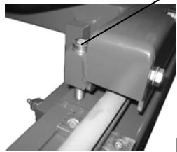
natural_image
Close-up of a mechanical assembly with no visible text or symbols[FIG.2]
natural_image
Close-up of a mechanical component with labeled point B, showing no visible text or symbols beyond the label.natural_image
Close-up of a flexible cable with labeled component F, no readable text or symbols present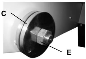
natural_image
Close-up of a mechanical component with a labeled part 'D' (no other text or symbols visible)
natural_image
Close-up of a metallic mechanical component with a flanged end (no visible text or symbols)[FIG.4]
natural_image
Close-up of a mechanical assembly with labeled component 'J' and reference marker '[FIG.5]' (no readable text or symbols beyond label)![K L [FIG.6]](/content/2020/04/80885/images/aacc5eba11c797b9c3d430dcbcf9e976340a8c91bf6c80ebccc964286d773215.jpg)

CONDITIONS DE GARANTIE
Explanation of the symbols
Use of pictograms on the machines (in color) and in the manual indicate safety warnings
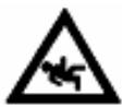
WATCH OUT! DANGER! General danger signal.

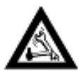
REQUIREMENT. The following must always be used with the machine:
• certified safety helmet
• certified ear protection
- certified safety goggles or certified eyeshade.

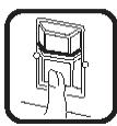
Carefully READ and assimilate the user's manual before operating the machine.

WARNING. Triangle and black marking on yellow background. Danger if instructions are ignored. Risk of injury to user or third party. Risk of damage to machine or tool.
PROHIBITED. Red circle with or without diagonal bar. Use or presence forbidden.

INFORMATION or specific instructions on how to use or check the machine.

This machine complies with the EC directive in force.

STOP symbol.

Safety goggles or eyeshade must be worn.

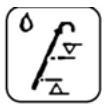
Loud noise in environment as defined by European Community directive.
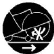
Disk rotation must stop when moving the machine at the work site.

Disk must be removed during slinging, loading, unloading and transport at the worksite.

Symbol on the product or its packaging showing that this product must not be treated as household waste. It must be deposited at a collection point approved for recycling of electric or electronic devices. By complying with proper disposal procedure when the product becomes obsolete, you help prevent environmental or health hazards that could result from mishandling the product. For further information on the recycling of this product, please contact your city hall, local waste drop-off center or the store where you bought the product.
Declaration of conformity
Manufacturer, HUSQVARNA CONSTRUCTION
PRODUCTS, 433 81 Gothenburg, Sweden, herewith declares that the machine TS1000F conforms to the DIRECTIVES:
• "MACHINES" modified (89/392/CEE)
- "LOW VOLTAGE" modified (73/23/CEE)
• "EMC" (89/336/CEE)
• "NOISE" (2000/14/CEE)
- "WASTE ELECTRICAL AND ELECTRNIC EQUIPEMENT (WEEE)" (2002/96/EC)

Christer Carlberg, Operations Manager
Husqvarna Construction Products
Preface
Before leaving our factory every machine passes an exacting inspection programme in which everything is checked minutely.
Following the instructions will ensure that your machine gives long service, in normal operating conditions. The user advice and spare parts mentioned in this document are given as an indication, and do not constitute an undertaking.
No warrantee will be granted in the event of errors or omissions, or for damage occur-ring during delivery, or caused by the design or use of the machine. We are very concerned about the quality of our products and we reserve the right to make any technical modifications to improve them, without warning.
This document will:
• provide the user with: information about the machine
• information about its possible uses
- prevent accidents due to unsuitable use, by an untrained person, during maintenance, repairs, overhauls, handling or transport
• improve the reliability and durability of the machine
- ensure correct use, regular maintenance, and fast fault finding in order to reduce repair costs and down time.

The manual should always be available at the place of work. It should be read and used by any person installing or using the machine.

The obligatory technical regulations in force in the country where the machine is used must also be adhered to for maximum safety.
Index
EXPLANATION OF SYMBOLS
Explanation of the symbols.... 2
CE DÉCLARATION
Conformity declaration.... 3
Preface 3
INDEX
Index....3
DESCRIPTION OF THE MACHINE
Description of the machine 4
TECHNICAL FEATURES
Technical features 5
INSTRUCTIONS DE SÉCURITÉ
Specific precautions 6
DO - DON'T 6
Check before operating 7
Gasoline (petrol) powered machine....7
Electric powered machine 7
Scrap 7
STARTING UP
Use 8
Handling - Transport....8
Installing the blade....8
Start 8
Stop 9
MAINTENANCE
Motor Gas maintenance 10
General maintenance 10
Belt tensioning.... 10
Important recommendations.... 10
Troubleshooting.... 11
Repairs 11
Spare parts.... 11
Warrantee.... 11
The instructions for use and spare parts found in this document are for information only and are not binding.
As part of our product quality improvement policy, we reserve the right to make any and all technical modifications without prior notice.

Description of the machine
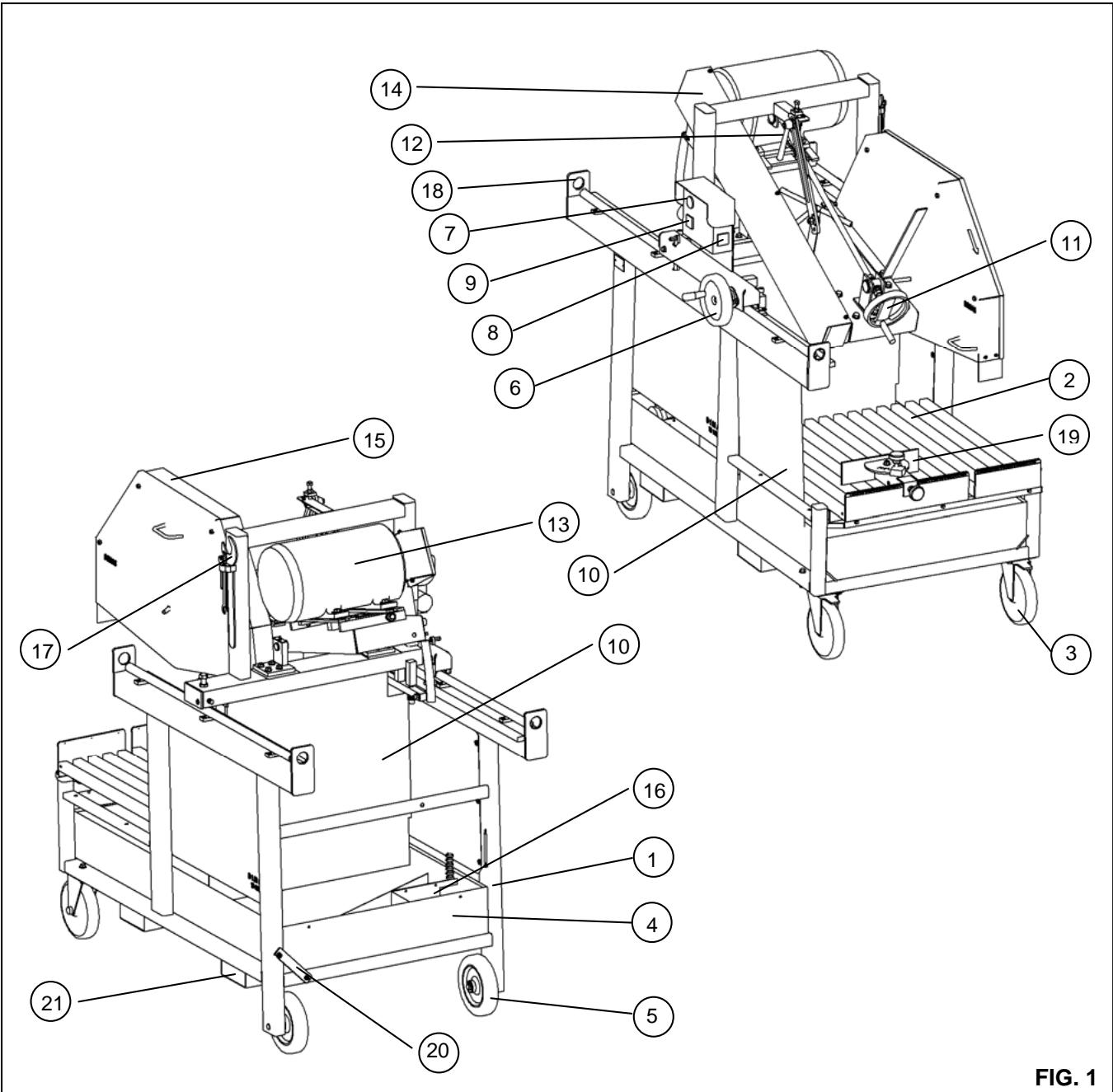
1 - Frame
2 - Table
3 - Swivelling wheel
4 - Water tank
5 - Fixed wheel
6 - Handwheel of the head advance
7 - Emergency stop
8 - Star / Triangle commutator
9 - Start / Stop switch
10 - Protective curtains
11 - Handwheel of the plunging head
12 - Head blocking lever
13 - Motor
14 - Belt guard
15 - Blade guard
16 - Water pump
17 - Operating key
18 - Sling eye
19 - Cutting guide
20 - Water tank blocking bar
21 - Transportation slots
TS1000F
General informations
| Blade (mm) | 900 / 1000 |
| Depth of cutting (mm) | 310 / 360 |
| Net weight (kg) | 324kg |
| Using weight (kg) | 440 kg |
| Dimensions (L x l x H - mm) | 1950 x 970 x 1700 |
| Shaft RPM | 1100 |
| Motor RPM | 1430 |
| Power (CV/kW) | 12 / 9 |
| Voltage (V) | 400 (3 phases) |
| Amps (A) | 18,5 |
| Electrical protection | IP54 |
| Max width (Right - mm) | 260 |
| Max width (Left – mm) | 450 |
| Water tank volume (litre) | 95 |
| Bore of the blade (mm) | 60 |
Noise emissions
| Power, LWA dB(A)EN ISO 3744 | 100 |
Noise – Pressure level
| Pressure, Lpa(dB) | |
| EN ISO 4871 | 99 |
Vibrations level
| According to ISO 5489 | |
| Aeq (m/s2), No cutting | 1,15 |
| Aeq (m/s2), during cutting | NC |
Nameplate
| HUSQVARNA CONSTRUCTION PRODUCTS FRANCE SA26 route Nationale – 41260 La Chaussée St-Victor | |||||
| TYPE | TS1000F | N° SERIE | |||
| ANNEE DE FABRICATION | kW | ||||
| MASSE UTILE | 324 | kg PUISSANCE | 9 | ||
| MAXI OUTIL | 1000 | mm PLAGE DE TENSION | 400 TRI | V | |
| ALESAGE | 60 | mm FREQUENCE | 50 | Hz | |
| T/MIN – RPM | 1100 | INT UTIL | 18,5 | A | |
| HUSQVARNA CONSTRUCTION PRODUCTS FRANCE SA26 route Nationale – 41260 La Chaussée St-Victor | |||||
| TYPE | TS1000F | SERIAL Number | |||
| MANUFACTURING YEAR | kW | ||||
| WEIGHT | 324 | kg POWER | 9 | ||
| MAX BLADE | 1000 | mm VOLTAGE | 400(3P) | V | |
| BORE | 60 | mm FREQUENCY | 50 | Hz | |
| T/MIN – RPM | 1100 | AMPS | 18,5 | A | |
Specific precautions
The manufacturer declines any liability resulting from misuse or modification of the saw.
Although designed for safe and reliable service when used according to instructions, there is a risk of harm to the user or damage to the saw unless certain precautions are taken. In particular, the following points must be regularly verified at the worksite:
- perfect technical conditions (saw used for suitable jobs considering potential risks; elimination of any malfunctions jeopardizing safety),
- use of a diamond disk for water sawing (cutting fresh, old or coated concrete, asphalt); use of any other type of disk (eg abrasive, saw) is strictly forbidden
- competent personnel (qualification, age, training, skill), who understand the manual in detail before starting work. Any electrical, mechanical or other defect or failure is to be inspected by an authorized service expert (eg electrician, maintenance manager, official dealer)
- observance of all warnings and directives marked on the machine (eg use of personal protective equipment); users must follow all instructions and comply with all safety rules
- no modification, transformation or addition that could potentially effect safety may be performed without the manufacturer's express authorization
- periodic inspections must be carried out as specified, at the intervals specified
- original manufacturer's spare parts must be used for any repairs.
DO
DO carefully read and make sure that you have understood all instructions before using the saw.
DO keep all safety guards in place
DO always wear approved ear, eye, head and respiratory protective equipment
DO always keep a safe distance from the disc and other moving parts
DO know how to stop the saw fast in case of emergency.
DO stop the motor and let it cool down before refueling.
DO check the disc, clamps and shafts for damage before installing the disk
DO use only discs marked with a maximum operating speed greater than that of the disk shaft
DO exercise all due care and follow all instructions when loading and unloading saw.
DON'T
DON'T allow other people nearby when starting the saw, refueling or cutting
DON'T run gasoline (petrol) motors in a confined space without appropriate ventilation
DON'T use damaged equipment or disks
DON'T operate the saw in the vicinity of flammable products. Sparks sprayed by the saw may cause fire or explosion.
DON'T authorize disc protection under 108°C
DON'T leave saw unattended with motor running.
DON'T use under the influence of alcohol or drugs.

IGNORING THESE WARNINGS MAY RESULT IN DEATH OR SERIOUS BODILY HARM.
Check before operating

Before starting, read the instructions carefully and get familiar with the machine.

Stop the motor

The work area must be orderly, well lit and hazard free (eg no moisture and no hazardous products nearby).

The operator must wear suitable personal protective equipment.

Safety earmuffs required.


Use only discs marked with a maximum operating speed greater than that of the disk shaft
Gasoline (petrol) powered machine
(see motor maintenance manual):


Always check ambient health & safety conditions.
• Fill up gas (petrol) tank.
- Check oil. Since the motor is often operated in inclined position, check frequently, in horizontal position, that oil level never falls below the second mark on the gauge.
Electric powered machine
Verify the following:

ELECTRICAL SAFETY: Must be connected to power source using a grounded 30mA residual differential current circuit-breaker. Should their be no such circuit breaker on the power supply network, please see our catalogue for different models available.
- Proper use of residual differential current (RDC) system, including periodic inspection. For tools with an RDC system built into the electrical cord or plug: should the cord or plug become damaged, repairs may be performed only by the manufacturer, their authorized agent or a qualified repair shop in order to avoid any hazard due to improper repair.
- Motor power supply: reinforced HO7 RNF electrical cable with 5 x 2.5 mm 4 section of up to 100 meters for 400V.
- Ensure that voltage of the power network matches that identified on the identity plate of the machine
- Three-phase motor: ensure that the rotational direction of the shaft corresponds to that shown by the arrow on the disk housing. If the motor does not rotate in the desired direction, inverse two phases by turning two power socket terminals.
• Machine must be grounded.
Scrap

Should the machine wear out or break, it must be disposed of in compliance with legislation in force.
Main materials:
- Motor: aluminum (AL) - steel (AC) - copper (CU) - polyamide (PA)
- Machine: sheet steel (AC) – cast iron (FT) - aluminum (AL)
Use
- Utilization: sawing marble, stone, granite, brick, cement and any covering material such as sandstone, earthenware, ceramics, etc.)
- Tools: ∅ 900mm or 1000mm water diamond discs with 60mm bore.
(For further information, see supplier)
No carbon disc!
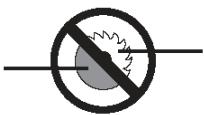
No wood or metal saw blade!

It is strictly forbidden to use the saw for any purpose other than that for which it has been designed.
Handling - Transport
- The two wheels (3) [FIG. 1] at the front of the machine pivot with the locking system.
- Use the four slinging rings (17) [FIG.1] on the struts.
- Sleeves (21) [FIG.1] allow the machine to be moved with a forklift.
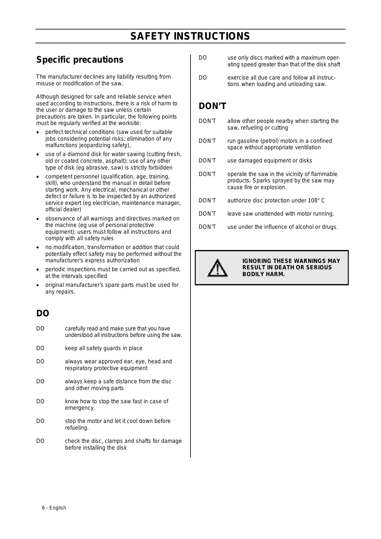
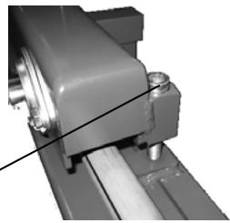
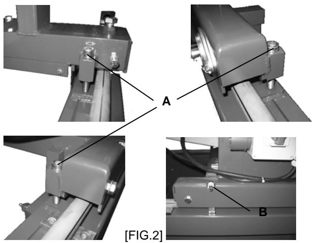
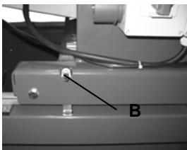
For transport, lock the head as follows:
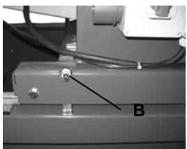
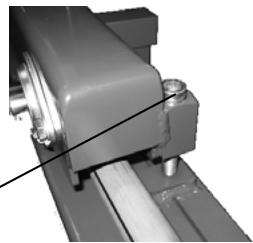
- Position the cutting head at the level for locking the transport screws (A)
- Using wrench (B), tighten the screws (A) until the casters are no longer n contact with the guide bars [FIG.2]
natural_image
Mechanical assembly diagrams showing four views (A, B) of a mechanical component with no visible text or symbols- Slide the wrench (B) into the slot provided [FIG.2].
To start using the machine, follow the transport procedure in reverse order.
Installing the disc

Unplug the machine form the electrical power supply.
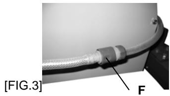
- Disconnect water supply tube (F) [FIG.3]
- Remove disc housing cover (15) [FIG.1]
- Loosen tightening nut (E) [FIG.3] with wrench provided
- Remove tightening flange (C)
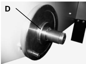
- Place disc on centering flange (D).
natural_image
Close-up of a flexible hose with labeled component F, shown in technical view (no text or symbols on the object itself)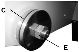
natural_image
Close-up of a mechanical component with labeled parts C and E (no text or symbols beyond labels)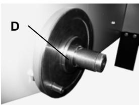
natural_image
Close-up of a mechanical component with a labeled section D, showing a shaft and housing (no text or symbols beyond label)
Rotate in the direction shown by the arrow on one of the sides.
Make sure that the bearing surfaces of the disk, flanges and shaft are clean.
- Put back the tightening flange (C),
- Tighten nut (E),
- Put back and fasten disk cover
- Reconnect the water supply tube (F).

For your safety and that of others, make sure that all guards are back in place before using.
Start

Danger : risk of cuts
Always remain attentive
Before starting the machine, remove any wrenches or setting tools.

Keep the safety guard in place for all work.
The machine is delivered with an uninstalled head advancement wheel (6) [FIG.1], packed in the accessory box. Install this wheel on its shaft [FIG.4].

natural_image
Close-up of a metallic mechanical component with a flanged handle (no visible text or symbols)[FIG.4]
For start-up and after transport, the machine must be unbridled:
- Loosen screws (A) until casters are in contact with the guide bars [FIG.2]
Next,
- Fill water tank (4) [FIG.1]. (Water pump starts automatically with motor).
- Place the material on table (2) according to desired cut, using cutting guide (18) and rulers [FIG.1].
- Start motor:
For heat engine machines:
→ Start motor according to manufacturer's instruction manual.
→ Allow motor to warm up.
For electric motor machines:
→ Start machine by pressing the "I" button of the contactor or by turning the contactor (9) to the "I" position. Turn switch (8) to "Y" position then to △. [FIG.1]
Next,
- Loosen control handle (12) and turn wheel (11) [FIG.1].
- Lower saw to desired cutting depth as indicated on graduated scale. Come down slowly so as to avoid stalling the motor.
- When the desired depth has been reached, retighten the control handle (12).
- Gently move the cutting head forward using the wheel (6) [FIG.1]. Advance slowly so as to avoid stalling the motor.
- Once the cut has been made, use wheel (6). to gently back the head up to its maximum rear position.
- Stop motor (see details in next section)

Before handling the cut material in any way, stop the motor and wait for the disc to come to a full stop.
Sound level at the workstation may exceed 85db (A) and therefore personal protection equipment must be worn.

Heat engine machines may not be operated in a confined space unless there is sufficient ventilation.
The exhaust gasses contain carbon monoxide. Exposure to this toxic gas can cause loss of consciousness and death.
Stop

Stop the motor
Heat engine: switch off at machine control panel
Electric motor: press red emergency stop button (7) or turn contactor (9) to position "O". Then turn switch (8) to position Y [FIG.1].
Maintenance
(Heat engine version only)

Heat engine: see motor maintenance manual.
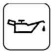
Oil level
Check oil level daily. See motor manual for oil change and oil filter replacement intervals.
Use:
• SAE 10W30 motor oil.
- Use class API MS, SD, SE or higher for gasoline (petrol) engines.
- Use class API CD or CE for diesel engines.

Dispose of used lubricants according to legislation in force.
To change oil, hold a funnel to oil drain outlet.
AIR FILTER:
- See motor maintenance manual for servicing intervals. For extremely dusty conditions, the filter element may have to be cleaned up to three times a day.
- Replace any damaged filters or packing seals.
General maintenance (all versions)
- Clean machine after each use
- Frequently empty the pan to remove saw sludge that may clog the water pump or wear it out prematurely
- Swill out pan with water
- Frequently clean the working areas of the head and table castors
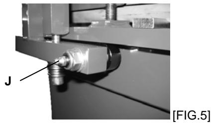
- Periodically add bearing grease to guide castor grease fittings (J) [FIG.5] and to disc shaft bearings
natural_image
Mechanical assembly with labeled component 'J' and reference to [FIG.5] (no readable text or symbols beyond label)
Store products in a safe and secure place, out of the reach of children. Remove all setting tools and wrenches.

Store diamond tool where it will not get warped or otherwise damaged.
Belt tension
After a certain amount of use, it may be necessary to re-stretch the belt. (Do not over-stretch)
- Loosen four screws (K) on motor [FIG. 6]
- Turn tension screw (L) one quarter turn to pull back the motor
- When tension is normal, re-tighten four screws (K) on motor
![K L [FIG.6]](/content/2020/04/80885/images/2291b8442927ad2e38e296e58c7404ce988b7b31ac6b06fc01c0c5f63fa083ca.jpg)

Never exceed original tension.
Important recommendations
- Periodically re-tighten hardware, especially after first hours of operation
- Check belt tension but never over-tighten
- When storing saw, remove disc and store carefully
- Make sure that disc is kept wet by regularly inspecting water injectors.
- Tighten disc properly.
- Keep disc, flange and shaft bearing surfaces clean.

The manufacturer declines any liability resulting from any misuse, modification or adaptation of the saw or from use of a motor that does not correspond to the manufacturer's original specifications
Troubleshooting
In case of malfunction see the table below for a solution to problems encountered.
The machine doesn't work:
| CAUSES | SOLUTIONS |
| Bad or damaged power cord | - Check that machine is properly plugged in (ie check plug and any extension cord)- Check power cord |
| No power from electrical network | - Have electrician check electrical outlet, circuit breakers... |
| Defective switch or damaged motor cable | - have checked by electrician or contact authorized repair service |
| Motor damaged (no power, unpleasant odor) | - have authorized repair service change motor |
Starting trouble:
| CAUSES | SOLUTIONS |
| Noncompliant three phase power supply (damaged motor cable) | - Have checked by electrician |
Pump won't start:
| CAUSES | SOLUTIONS |
| Power cord is not connected or is damaged | - Check power cord |
| No current in circuit or electrical outlet | - Have circuit or outlet checked by electrician |
No water comes out of pump:
| CAUSES | SOLUTIONS |
| Air bubble may have formed inside pump body | - Holding the pump by the discharge tube, remove the pump from the liquid and then re-immerse it |
| No current in circuit or electrical outlet | - Remove filter and use a small screwdriver to clean the turbine working area of any residue |
Repair service
S A V
We remain at your disposal for the fastest repairs at the best prices (see addresses at end of manual).
Spare parts
To save time and ensure rapid delivery of spare parts, please make sure your order includes the details on the machine information plate as well as the reference of the replacement part. (See spare part list delivered with machine).

Guarantee
DURATION
This guarantee is valid for six months effective from the date of purchase by the user (date on the retailer's bill).
SCOPE
The guarantee is limited to free replacement of parts having manufacturing defects recognized by Dimas (except for wearing parts and consumables) if repairs are performed in a workshop operated or approved by Dimas. The manufacturer will not be held accountable for any direct or indirect material damages or consequential losses caused by persons or things following failure or stoppage of the machine.
CONDITIONS OF GUARANTEE
To be entitled to the guarantee, the user must return the certificate of guarantee duly completed to Dimas within eight days of purchase. Should a problem occur during the guarantee period, our customer service department will tell you of the best way to solve it and, if necessary, inform you of the closest approved service center. You may also ship the machine, at your expense, to our Customer Service department. In this case, please attach the bill of sale, as well as a report describing the problem encountered and asking that it be fixed under the terms of the guarantee. A technical diagnostic will be performed without delay on reception of the machine and you will be sent our conclusions.
EXCLUSIONS
This guarantee expressly excludes damage or failures resulting from:
- abnormal utilization, as well as errors made during transport, handling or maintenance
- use of lubricants or fuels that are substandard or not recommended by Dimas
- use of other than original parts or accessories
- servicing by unapproved personnel
- use of a defective or unsuitable diamond tool.
(We recommend use of Dimas tools).
Merchandise is shipped at the buyer's expense and risk. In case of transport incident, it is the buyer's responsibility to take any action against the transporter in the form and within the time specified by the laws in force.
Christer Carlberg, Operations Manager
Husqvarna Construction Products
natural_image
Mechanical assembly diagrams showing four views (A, B) of a mechanical component with no visible text or symbolsnatural_image
Close-up of a flexible hose with labeled component [Abb.3] and letter F, no readable text or symbols beyond labels
natural_image
Close-up of a mechanical component with labeled parts C and E (no text or symbols beyond labels)
natural_image
Close-up of a mechanical component with a labeled point D, showing a shaft and housing (no text or symbols beyond label)
natural_image
Close-up of a metallic mechanical component with a threaded end (no visible text or symbols)[Abb. 4]
natural_image
Close-up of a mechanical assembly with a labeled component 'J' (no readable text or symbols)[Abb. 5]

Christer Carlberg, Operations Manager Husqvarna Construction Products
Description de la machine
natural_image
Mechanical assembly diagrams showing four views (A, B) of a mechanical component with no visible text or symbolsnatural_image
Close-up of a flexible cable with a labeled component, shown in technical view (no text or symbols on the cable itself)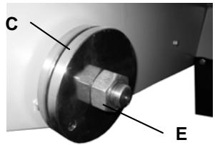
natural_image
Close-up of a mechanical component with labeled parts C and E (no readable text or symbols beyond labels)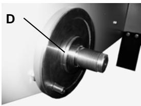
natural_image
Close-up of a mechanical component with a labeled section D, showing a shaft and housing (no text or symbols beyond label)
natural_image
Close-up of a metallic mechanical component with a U-shaped fitting (no visible text or symbols)[FIG.4]
natural_image
Mechanical assembly with labeled component 'J' and reference to [FIG.5] (no readable text or symbols beyond label)![K L [FIG.6]](/content/2020/04/80885/images/fd771454c837f55fd1d4f81295b7f4629a83952b89be4f00c949fead774b189f.jpg)

Christer Carlberg, Operations Manager Husqvarna Construction Products
Prefacio del manual
natural_image
Mechanical assembly diagrams showing four views (A, B) of a mechanical component with no visible text or symbolsnatural_image
Close-up of a flexible cable with a labeled component, shown in technical view (no text or symbols on the cable itself)
natural_image
Close-up of a mechanical component with labeled parts C and E (no text or symbols beyond labels)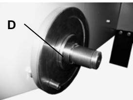
natural_image
Close-up of a mechanical component with a threaded shaft and circular base, labeled 'D' (no text or symbols on the object itself)
natural_image
Close-up of a metallic mechanical component with a flanged end (no visible text or symbols)[FIG.4]
natural_image
Mechanical assembly diagram showing a bolted joint with threaded components and a labeled component 'J' (no text or symbols beyond label)![K L [FIG.6]](/content/2020/04/80885/images/4423c92aa22b7f3d45db4cc35529fcd271616955c99068f8d81ca0888e843e76.jpg)

Christer Carlberg, Operations Manager Husqvarna Construction Products
Inleiding
BESCHRIJVING MACHINE
natural_image
Mechanical assembly diagrams showing four views (A, B) of a mechanical component with no visible text or symbolsnatural_image
Close-up of a flexible cable with labeled component F, shown in technical view (no text or symbols beyond labels)
natural_image
Close-up of a mechanical component with labeled parts C and E (no text or symbols beyond labels)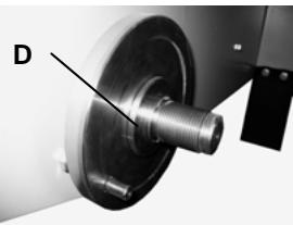
natural_image
Close-up of a mechanical component with a labeled point D, showing a shaft and housing (no text or symbols beyond label)
natural_image
Close-up of a metallic mechanical component with a U-shaped fitting (no visible text or symbols)[FIG.4]
natural_image
Mechanical assembly with labeled component 'J' and reference to [FIG.5] (no readable text or symbols beyond label)![K L [FIG.6]](/content/2020/04/80885/images/d51b81957a4947caa3b1bc3e640e2f5effe82d7c162b939d162c0dbe7df4307f.jpg)

Christer Carlberg, Operations Manager
Husqvarna Construction Products
Förord
INNEHÅLLSFÖRTECKNING
Hantering - Transport
natural_image
Mechanical assembly with mounting bracket and tool (no visible text or symbols)A
natural_image
Mechanical assembly showing a rotating shaft and housing with a central shaft (no visible text or symbols)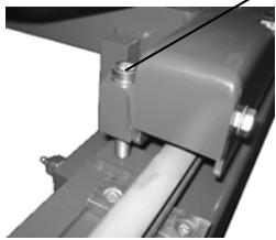
natural_image
Close-up of a mechanical assembly with a cylindrical component and mounting bracket (no visible text or symbols)[FIG.2]
natural_image
Close-up of a mechanical component with labeled point B, no visible text or symbols beyond labelnatural_image
Close-up of a flexible cable with labeled component F, shown in technical view (no text or symbols on the cable itself)
natural_image
Close-up of a mechanical component with labeled parts C and E, showing a bolted joint and flange (no text or symbols beyond labels)
natural_image
Close-up of a mechanical component with a labeled point D, showing a shaft and housing (no text or symbols beyond label)
natural_image
Close-up of a metallic mechanical component with a U-shaped fitting (no visible text or symbols)[FIG.4]
natural_image
Mechanical assembly with labeled component 'J' and reference to [FIG.5] (no readable text or symbols beyond label)![K L [FIG.6]](/content/2020/04/80885/images/b380e2eba19fd0539560263bf6d25cc958d93197ce3f7c79dd8c228778504a3c.jpg)

| WARRANTY CONDITIONS |
| 1. PERIODThe warranty is acknowledged as of the date of purchase (date of the invoice of the distributor) and is valid for a period of 12 months. |
| 2. WARRANTYThe warranty is limited to the free of charge replacement of parts recognised as defective by Husqvarna (excluding wear components and consumables) providing the repair is made within after-sales service of Husqvarna or a recognised Husqvarna repair centre. |
| The manufacturer is not responsible for any direct or indirect, material or immaterial, damages caused to persons or things by failure of the machine or the non operation of the machine. |
| 3. WARRANTY CONDITIONSTo benefit the warranty, it is necessary to return the joined warranty certificate, duly completed, to Husqvarna within eight days of the purchase.In case of failure of the machine during the warranty period, our after-sales services will inform you of the appropriate and most effective method of dealing with your claim and advise you if necessary of your nearest approved service centre.As an alternative, you may return, at your cost, the machine together with a written description of the problem and damages with a copy of the invoice directly to our after sales department where upon a full investigation will be instigated without delay. |
| 4, EXCLUSIONSWarranty will not be applied for damages or failures caused by:- incorrect use, error in transportation, handling or maintenance,- use of incorrect fuel or lubricants not advised by Husqvarna,- use of non-genuine parts or accessories,- repairs made by non approved service centres,- use of incorrect specifications of cutting tools. (We suggest the use of Husqvarna tools). |
| The goods are returned at the sole responsibility of the Buyer who must appeal against the transporter in the usual manner without delay. |
Español
Theorem 1.2. (A) Let f be a finite field and let g be the set of all elements of f . Then
(1) m = 311 .
Indien gewenst kunt U de machir After Saleserviedienst, terug, o
Chard's, 1980. March 2014, the first week of this
Warranty certificate
- Certificat de garantie
• Garantie-Zertifikat
Place here CE sticker with serial N°
To benefit from the warranty, it is mandatory to return, within eight days after the purchase, the attached warranty certificate.
Warranty certificate
Certificat de garantie • Garantie-Zertitikat • Certificato di garanzia • Garantie bewijs • Certificado de garantia • Certificado de garantia • Garanticertifikat
Company :
Société • Gesellschaft • Societa • Maatchappij • Sociedade • sociedad • Företag
Address :
Adresse • Adresse • indirizzo • Adres • Endereco • Direccion • Adress
Date of Acquisition :
Date d'achat • Datum des Kaufs • Data di acquisto • Datum van aankoop • Data de compra • Fecha de comprar • Inköpsdatum
Machine Type :
Type de la machine • Maschinen Type • Tipo della macchina • Machine Type • Tipo de maquina • Tipo de maquina • Maskintyp
Machine Serial Nr :

- Préface
- Description de la machine
- Manutention - Transport
- CONDITIONS DE GARANTIE
- Explanation of the symbols
- Declaration of conformity
- Preface
- This document will:
- Index
- Description of the machine
- TS1000F
- Nameplate
- Specific precautions
- DO
- DON'T
- Check before operating
- Gasoline (petrol) powered machine
- Electric powered machine
- Scrap
- Use
- Handling - Transport
- Installing the disc
- Start
- Next,
- For heat engine machines:
- For electric motor machines:
- Stop
- Maintenance
- General maintenance (all versions)
- Belt tension
- Important recommendations
- Troubleshooting
- Repair service
- Spare parts
- Guarantee
- DURATION
- SCOPE
- CONDITIONS OF GUARANTEE
- EXCLUSIONS
- Prefacio del manual
- Inleiding
- BESCHRIJVING MACHINE
- Förord
- INNEHÅLLSFÖRTECKNING
- Hantering - Transport
- Warranty certificate
- Place here CE sticker with serial N°
- To benefit from the warranty, it is mandatory to return, within eight days after the purchase, the attached warranty certificate.
- Company :
- Address :
- Date of Acquisition :
- Machine Type :
- Machine Serial Nr :
Brand : HUSQVARNA
Model : TS 1000 F
Category : Chainsaw