
PP 455 E - Chain saw HUSQVARNA - Free user manual and instructions
Find the device manual for free PP 455 E HUSQVARNA in PDF.
| Product type | Hydraulic power unit |
| Brand | HUSQVARNA |
| Model | PP 455 E |
| Category | Chainsaw (hydraulic power unit for wall saw and cable saw) |
| Height | 970 mm |
| Weight (with oil) | 140 kg |
| Power supply | 400 V three-phase, 32-63 A, 50 Hz (other versions available) |
| Nominal hydraulic power | 25 kW / 33.5 hp |
| Maximum oil flow | 65 L/min (17 gal/min) |
| Maximum hydraulic pressure | 230 bars |
| Oil tank capacity | 16 L |
| Cooling | Water-cooled electric motor; water-cooled oil cooler |
| Sound level (acoustic power) | 101 dB(A) guaranteed |
| Main functions | Hydraulic hose supply, display screen, remote control with radio, emergency stop, power selection and fuse |
| Compatibility | Wall saws WS 355, WS 463, WS 462, WS 460; cable saw CS 2512 |
| Included equipment | Hydraulic power unit, remote control (with radio depending on market), charger adapter, radio bag, hydraulic hoses 8 m, Canbus cable 8 m |
| Maintenance | Oil change (approx. 16 L, viscosity 68), filter replacement, daily check of level and tire pressure, service after 100 h |
| Safety | Emergency stop, stop button, motor protection, voltage and temperature sensors, mandatory personal protective equipment (helmet, goggles, gloves, etc.) |
| Repairability | Repairs by a Husqvarna authorized workshop; original parts recommended |
| Standards | CE, EN ISO 12100, EN 55014, EN 60204, etc. |
Frequently Asked Questions - PP 455 E HUSQVARNA
User questions about PP 455 E HUSQVARNA
0 question about this device. Answer the ones you know or ask your own.
Ask a new question about this device
Download the instructions for your Chain saw in PDF format for free! Find your manual PP 455 E - HUSQVARNA and take your electronic device back in hand. On this page are published all the documents necessary for the use of your device. PP 455 E by HUSQVARNA.
USER MANUAL PP 455 E HUSQVARNA
Please read the operator's manual carefully and make sure you understand the instructions before using the machine.

Symbols on the machine:
WARNING! The machine can be a dangerous tool if used incorrectly or carelessly, which can cause serious or fatal injury to the operator or others.
Please read the operator's manual carefully and make sure you understand the instructions before using the machine.
Always wear:
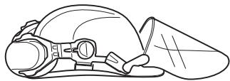
Approved protective helmet
Approved hearing protection
- Protective goggles or a visor
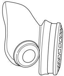
- Breathing mask
This product is in accordance with applicable EC directives.
WARNING! High current.
Environmental marking.
Symbols on the product or its packaging indicate that this product cannot be handled as domestic waste. It must instead be submitted to an appropriate recycling station for the recovery of electrical and electronic equipment.
By ensuring that this product is taken care of correctly, you can help to counteract the potential negative impact on the environment and people that can otherwise result through the incorrect waste management of this product.
For more detailed information about recycling this product, contact your municipality, your domestic waste service or the shop from where you purchased the product.


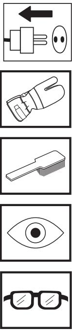
Symbols in the operator's manual:
Inspection and/or maintenance should be carried out with the motor switched off and the plug disconnected.
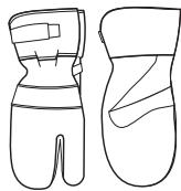
Always wear approved protective gloves.
Regular cleaning is required.
Visual check.
Protective goggles or a visor must be worn.
Contents
KEY TO SYMBOLS
Symbols on the machine: 2
Symbols in the operator's manual: 2
CONTENTS
WHAT IS WHAT?
What is what on the hydraulic unit? 4
SAFETY INSTRUCTIONS
Steps before using a new hydraulic unit 5
Personal protective equipment 5
Machine's safety equipment 6
General safety precautions 7
General working instructions 8
PRESENTATION
PP 455 E 9
ASSEMBLY
Assembling/Installing equipment 10
SETTINGS AND ADJUSTMENTS
Menu functions 12
Start menu 12
Operations menu 12
Settings 14
STARTING AND STOPPING
Wall sawing 18
Wire cutting 19
MAINTENANCE
Error messages 21
Service 22
Maintenance 22
TECHNICAL DATA
PP 455 E 23
EC-declaration of conformity 24
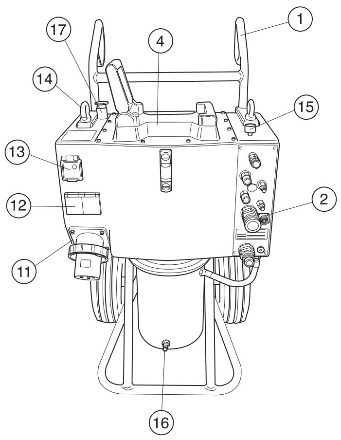
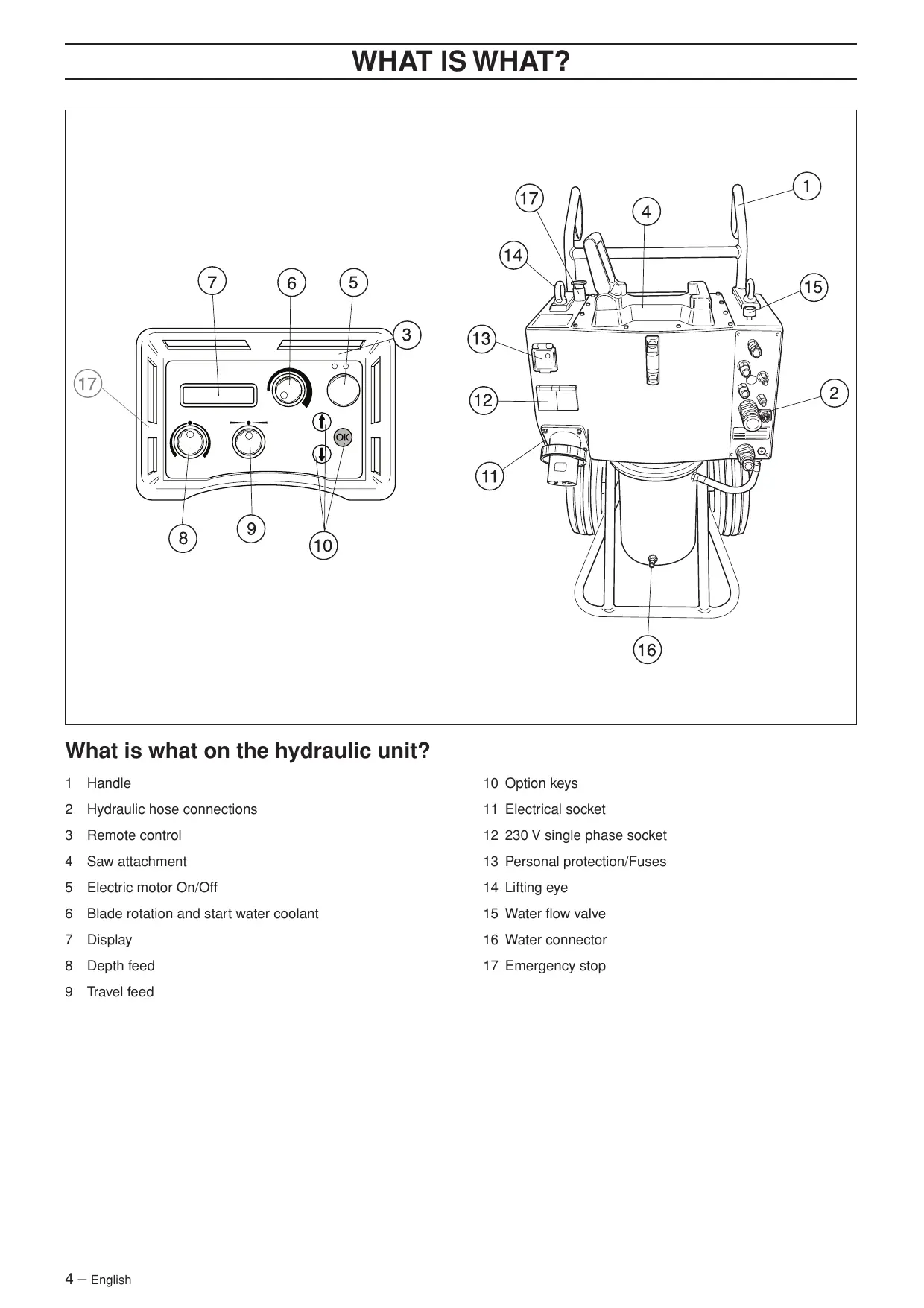
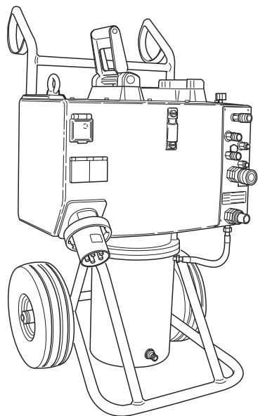
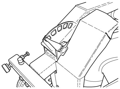
What is what on the hydraulic unit?
1 Handle
2 Hydraulic hose connections
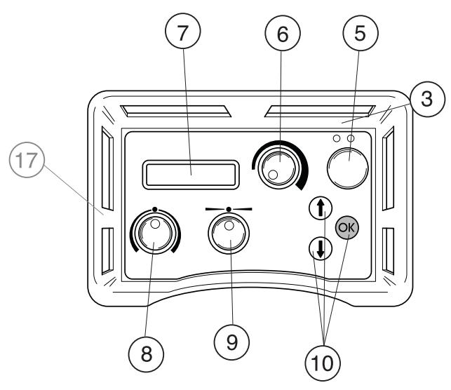
3 Remote control
4 Saw attachment
5 Electric motor On/Off
6 Blade rotation and start water coolant
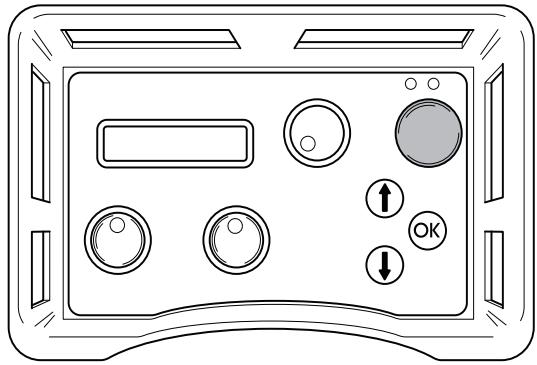
7 Display
8 Depth feed
9 Travel feed
10 Option keys
11 Electrical socket
12 230 V single phase socket
13 Personal protection/Fuses
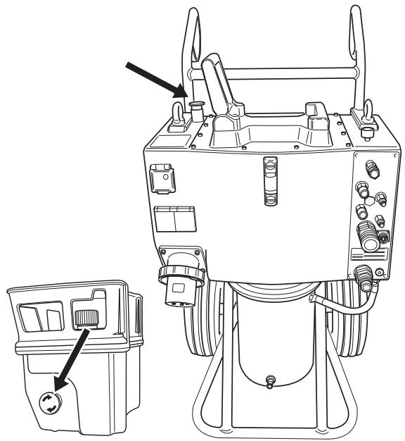
14 Lifting eye
15 Water flow valve
16 Water connector
17 Emergency stop
Steps before using a new hydraulic unit
- Please read the operator's manual carefully and make sure you understand the instructions before using the machine.
- This machine is only intended for use together with a Husqvarna WS 355, WS 463, WS 462, WS 460 and CS 2512. All other use is forbidden.
- Read through the manual supplied with the hydraulic tool before starting to use the machine.
- The machine can cause serious personal injury. Read the safety instructions carefully. Learn how to use the machine.
Always use common sense
It is not possible to cover every conceivable situation you can face. Always exercise care and use your common sense. Avoid all situations which you consider to be beyond your capability. If you still feel uncertain about operating procedures after reading these instructions, you should consult an expert before continuing.
Do not hesitate to contact your dealer if you have any more questions about the use of the machine. We will willingly be of service and provide you with advice as well as help you to use your machine both efficiently and safely.
Let your Husqvarna dealer regularly check the machine and make essential adjustments and repairs.
All information and all data in the Operator's Manual were applicable at the time the Operator's Manual was sent to print.

WARNING! Under no circumstances should you modify the original design of the machine without approval from the manufacturer. Always use original spare parts. Unauthorised modifications and/or accessories may lead to serious injury or death to the user or others.
Personal protective equipment

WARNING! You must use approved personal protective equipment whenever you use the machine. Personal protective equipment cannot eliminate the risk of injury but it will reduce the degree of injury if an accident does happen. Ask your dealer for help in choosing the right equipment.
- Protective helmet
Hearing protection - Protective goggles or a visor
- Breathing mask
Heavy-duty, firm grip gloves.
- Tight-fitting, heavy-duty and comfortable clothing that permits full freedom of movement.
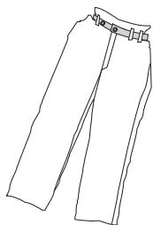
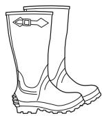
- Boots with steel toe-caps and non-slip sole.
Always have a first aid kit nearby.

Machine's safety equipment

This section describes the machine's safety equipment, its purpose, and how checks and maintenance should be carried out to ensure that it operates correctly. See the "What is what?" section to locate where this equipment is positioned on your machine.

WARNING! Never use a machine that has faulty safety equipment! Safety equipment must be inspected and maintained. See instructions under the heading Checking, maintaining and servicing the machine's safety equipment. If your machine does not pass all the checks, take it to a service workshop for repair.
IMPORTANT! All servicing and repair work on the machine requires special training. This is especially true of the machine's safety equipment. If your machine fails any of the checks described below you must contact your service agent. When you buy any of our products we guarantee the availability of professional repairs and service. If the retailer who sells your machine is not a servicing dealer, ask him for the address of your nearest service agent.
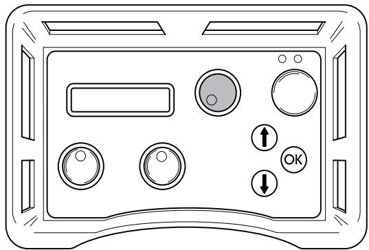
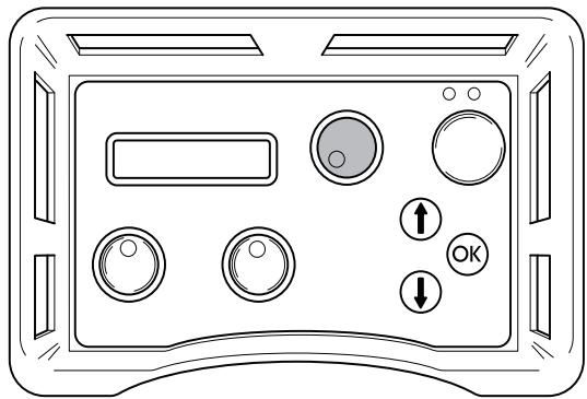
Start button
The start button must be pushed and held to be able to start the blade rotation. This in order to prevent unintended starting of the blade rotation.
Checking the start button
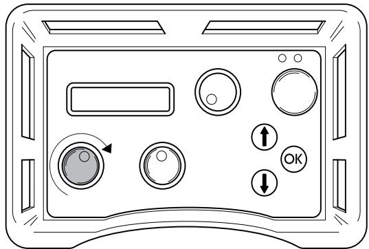
- Turn the knob for blade rotation without pushing and holding the start button. The blade rotation must not start.
- Push and hold the start button and turn the knob for blade rotation. Now the blade rotation shall start.
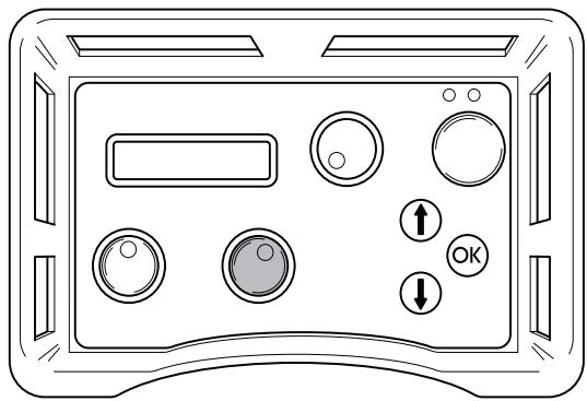
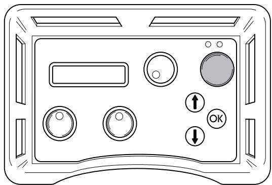
Emergency stop and stop button
The hydraulic unit is equipped with an emergency stop and the remote control with a stop button. These are used to be able to quickly shut down the hydraulic unit.
Check the emergency stop and stop button
Startbladerotation
- Push the emergency stop on the hydraulic unit and check that the blade rotation stops. Check the stop button on the remote control in the same way.
General safety precautions
Do not use the machine without first reading and understanding the contents of this Operator's Manual.

WARNING! There is always a risk of shocks from electrically powered machines. Avoid unfavourable weather conditions and body contact with lightning conductors and metal objects. Always follow the instructions in the Operator's manual to avoid damage.
- Never use the machine if you are tired, if you have drunk alcohol, or if you are taking medication that could affect your vision, your judgement or your co-ordination.
- Wear personal protective equipment. See instructions under the heading Personal protective equipment.
- Never carry the machine by means of the cord and never pull out the plug by pulling the cord.
- Keep all cords and extension cords away from water, oil and sharp edges. Make sure the cord is not pinched in doors, fences or the like. Otherwise it can cause the object to become live.
- Check that the cord and extension cord are intact and in good condition.
- Never use the machine if the cord is damaged, hand it in to an authorized service workshop for repair.
- Do not use an extension cord while it is rolled up to avoid overheating.
- The machine should be connected to an earthed outlet socket.
- Check that the mains voltage corresponds with that stated on the rating plate on the machine.
- Keep all parts in good working order and ensure that all fixtures are properly tightened.
- Never use a machine that is faulty. Carry out the checks, maintenance and service instructions described in this manual. Some maintenance and service measures must be carried out by trained and qualified specialists. See instructions under the heading Maintenance.
- Do not modify safety equipment. Check regularly that they function as they should. The machine must not be run with defective or disassembled safety equipment.
- Never allow anyone else to use the machine without first ensuring that they have understood the contents of the operator's manual.
- People and animals can distract you causing you to lose control of the machine. For this reason, always remain concentrated and focused on the task.
- Be careful as clothing, long hair, and jewellery can get caught in moving parts.
- Observe care when lifting. You are handling heavy parts, which implies the risk of pinch injuries or other injuries.
Transport and storage
- Always switch off the power to the hydraulic unit and pull out the electric cable before moving the equipment.
- Store the equipment in a lockable area so that it is out of reach of children and unauthorised persons.
- Use the cases provided to store the equipment.
General working instructions

WARNING! This section describes basic safety directions for using a wall saw. This information is never a substitute for professional skills and experience. If you get into a situation where you feel unsafe, stop and seek expert advice. Contact your dealer, service agent or an experienced user. Do not attempt any task that you feel unsure of!
- All operators shall be trained in the use of the machine. The owner is responsible for ensuring that the operators receive training.
- Check that all couplings, connections and hydraulic hoses are in full working order.
- Keep the hydraulic hoses and couplings free from dirt.
- Do not misuse hoses.
- Do not use hoses that are distorted, worn or damaged.
- Make sure that all hoses and electrical cables are connected to the machine correctly before you start the machine.
- Check that the hoses are connected correctly to the machine and that the hydraulic couplings lock as intended before pressurising the hydraulic system. The couplings are locked by turning the outer sleeve on the female coupling so that the slot moves away from the ball.
The pressure hoses in the system must always be connected to the tool's intake. The return hoses in the system must always go to the tool's outlet. Confusing the connections can cause the tool to work in reverse, which can result in personal injury.
- Never use the hydraulic hoses to lift the machine.
- Check the machine, couplings and hydraulic hoses daily for leakage. A rupture or leak can cause a "hydraulic fluid injection" in the body or result in other serious physical injury.
- Never disconnect the hydraulic hoses without first shutting off and disconnecting the hydraulic unit and ensuring the motors have stopped completely.
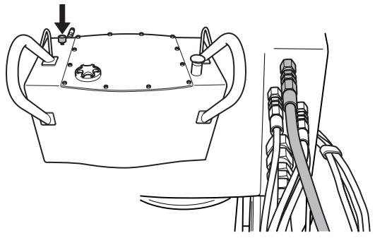
- If despite all precautions an emergency situation should arise, press the red emergency stop button on the top of the unit or press the green start/stop button on the remote control.
- Do not exceed the specified hydraulic fluid flow or pressure for the tool being used. Excessive pressure or flow can result in rupturing.
- Do not check for leakage with your hands. Contact with the leak can result in serious personal injury caused by the high pressure in the hydraulic system.
-
Check that power cables and the Canbus cable are not damaged or can be damaged while working.
-
Working close to power lines:
Hoses that are marked and approved as electrically non conductive must be used when using hydraulic tools on or in the vicinity of electrical cables. The use of other types of hoses can result in serious physical injury or even death.
When replacing hoses, hoses marked non-conducting dielectric" must be used. The hoses must be regularly checked for their electrical conductive insulation in accordance with special instructions. - Working close to gas conduits:
Always check and mark out where gas pipes are routed. Cutting close to gas pipes always entails danger. Make sure that sparks are not caused when cutting in view of the risk of explosion. Remain concentrated and focused on the task. Carelessness can result in serious personal injury or death. - Run the hydraulic system until it reaches its operation temperature of 30^ before starting to saw, to reduce return pressure and other wear.
- Never leave the machine unsupervised with the engine running.
- Always saw in a manner that permits easy access to the emergency stop.
- Make sure that there is always another person close at hand when you use the machines, so that you can call for help if an accident should occur.
- People that need to be in close proximity of the machine must wear hearing protection as the sound level when cutting exceeds 85 dB(A).
- The safety distance is 4 meters (15 ft) from the machine.
- Do not use the machine in bad weather, such as dense fog, rain, strong wind, intense cold, etc. Working in bad weather is tiring and can lead to dangerous conditions, e.g. slippery surfaces.
- Ensure that the working area is sufficiently illuminated to create a safe working environment.
Always ensure you have a safe and stable working position. - Observe care when lifting. You are handling heavy parts, which implies the risk of pinch injuries or other injuries.
PP 455 E
It is our wish that you will be satisfied with your product and that it will be your companion for a long time. Think of this operator's manual as a valuable document. By following its content (using, service, maintenance etc) the life span and the second-hand value of the machine can be extended. If you will sell this machine, make sure that the buyer will get the operator's manual.
A purchase of one of our products gives you access to professional help with repairs and services whenever this may be necessary. If the retailer who sells your machine is not one of our authorised dealers, ask him for the address of your nearest service workshop.
Husqvarna Construction Products has a policy of continuous product development. Husqvarna reserves the right to modify the design and appearance of products without prior notice and without further obligation introduce design modifications.
General
Husqvarna PP 455E is the latest hydraulic unit from Husqvarna. The unit is a further developed of the former unit PP 355E and has been produced to match the new Hsqvarna products and products to be launched in the future.
PP 455 is a very compact hydraulic unit, only 970~mm high.
Among the new major features is the water cooled motor, which means the user can use more power for longer periods than before. New improved software, adjustable handle and the possibility to attach a wall saw from the WS 400 series on the unit are other new features that facilitate the daily use of the product.
PP 455E is supplied with the following equipment:
1 x hydraulic unit
1xremotecontrolwithradiocontrol*
1 x charging adapter (12 V/230 V)
- 1 x bag for the radio unit with accessories
1x hose assembly, 8 m
1 x Canbus cable, 8 m
*The machine is only equipped with a radio on some markets.
Assembling/Installing equipment
When the machine has been transported to a suitable site, it should be connected:
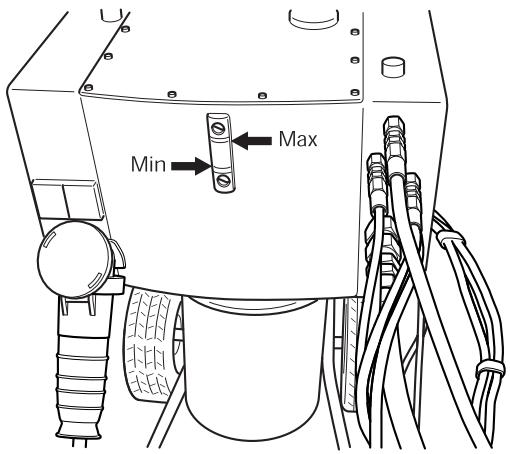
1 Check the hydraulic fluid level in the power unit. This is checked with the level indicator.
Min. level = red line
Max. level = black line
Do not exceed the max. level when filling the tank with hydraulic fluid. The hydraulic fluid expands when it gets hot and can overflow if the level is too high. Tank volume 16 I (4.2 US gallons).
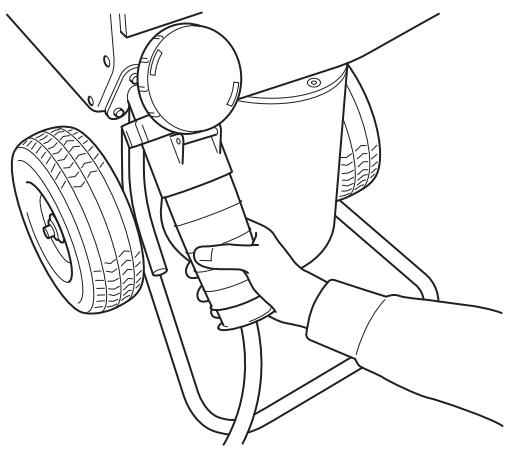
2 Connect the incoming power cable (400 V, 63 A or 400 V, 32 A European connector). The cable must be three-phase and earthed. When the machine is equipped with a single phase socket there must also be a neutral otherwise the single phase socket on the distribution box will not work.
3 The power unit must be connected through a 63 A fuse in order to use maximum power. If connected through a 32 A fuse, the saw must be operated at low pressure, and with that cut less effectively to avoid overloading the fuse.
4 Connect the incoming water hose to the water coupling on the bottom of the motor front on the hydraulic unit.
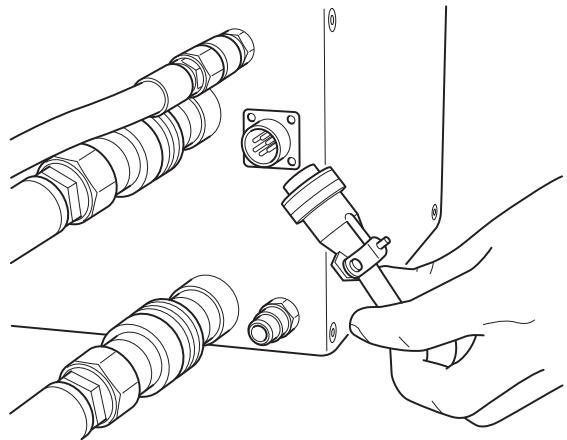
5 Connect the remote control using the supplied Canbus cable. Tighten the cable connector screws by hand.
When the machine is equipped with a radio, a radio antenna can be connected instead of a Canbus cable. This is screwed into the same socket as where the Canbus cable should have been fitted.
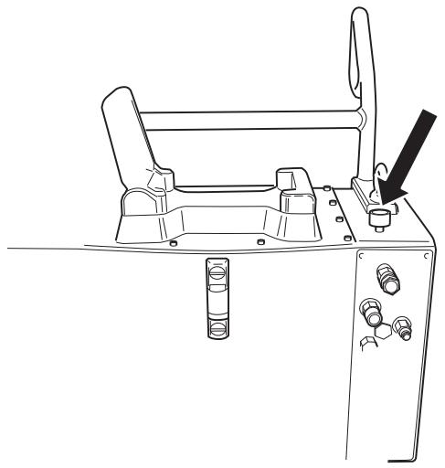
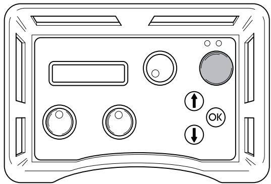
6 Check that the emergency stop button on the power unit and the stop button on the remote control are not pressed by turning the them clockwise.
7 The display now shows SELECT FUSE 32A". If the available fuse is 32 A, confirm this by pressing the membrane key marked OK". If there is a 63 A fuse available, press the membrane key marked up arrow". The display now indicates SELECT FUSE 63A". Confirm this by pressing the membrane key marked OK". (Menu functions / 2. Select fuse".)
8 Connect the hose assembly. In this position, connect the hydraulic hoses. A pressure equalizing function making it easier to connect the hoses is now activated. This spares the seals in the hydraulic couplings.
There are two types of hydraulic hoses for the unit:
-
On a wall saw in the WS 400 series, the four thin hoses control the saw's motion motors, i.e. the saw's blade motion and the saw's trolley motion. The two thick hoses drive the blade.
-
When a wire saw CS 2512 is connected to the unit, the two thin hoses control the tension on the magazine arm while the two thick hoses drive the wire.
Some couplings on the unit have a red marking sign on the coupling. The hoses with red discs should be connected to these couplings.
9 Connect the water hose between the unit and the saw's water connector and open the water flow valve on top of the unit by turning the handwheel anticlockwise.
When the power cable and water hoses and hose assembly are connected, the machine can be started.
- Press OK to confirm the selection.
10 The hydraulic output must be set according to which machine is connected to the hydraulic unit. Select one of the following:
- 25 kW, 230 bar, 65 l/min
- 15 kW, 210 bar, 45 l/min or
- 9 kW, 140 bar, 40 l/min
11 The display now shows HUSQVARNA PP 455E START ELECTRIC MOTOR". If the display does not show this, follow the instructions shown on the display.
Menu functions
The menus, shown on the display, are grouped in menus, sub-menus (Settings") and part menus. The menus are divided into two sections:
- Start menu: Here you can select under which conditions the hydraulic unit shall work.
- Operations menu: Information concerning the operating status is shown here.
Start menu
The start menu is shown each time the power to the hydraulic unit is switched on. The menu consists of three steps:
Select fuse
The fuse rating must be set according to the fuse the hydraulic unit is connected to.
Select 16 A, 32 A or 63 A.
- Press OK to confirm the selection. Step three is then displayed.
Select the output
The hydraulic output must be set depending on the machine connected to the hydraulic unit. Select one of the following options:
25 kW, 230 bar, 65 l/min (3300 psi, 17 US gpm)
15 kW, 210 bar, 45 l/min (3000 psi, 12 US gpm)
9 kW, 140 bar, 40 l/min (2000 psi, 10 US gpm)
Press OK to confirm the selection.
Husqvarna PP 455E Connect hose assembly
- Press OK when all hoses are connected.
Operations menu
The operations menu starts after step 3 in the start menu. All information about operations and all setting options are accessed from this menu.
The operations menu consists of eight menus:
1 a. Husqvarna PP-455, b Status
2 Water coolant ON/OFF?
3 Phase 1, Phase 2, Phase 3
4 Settings
5 Time
6 Total machine time
7 Battery status (only machines equipped with a radio)
8 Radio channel (only machines equipped with a radio)
1.a Husqvarna PP-355, Start electric motor
Press the green button on the remote control to start the electric motor.
1b. Status
Status is the main information that is always shown on the display when the hydraulic unit with connected machine is operational:
STATUS OK, signifies that the unit is operational and no warning messages have been issued.
- KV xx, where KV represents water coolant and xx ON or OFF. What is shown depends on whether the water coolant is switched on or off.
- yyy BAR, where yyy represents the instantaneous operating pressure.
- When time is switched on: mm:ss, is also shown, i.e. the time in minutes and seconds.
2. Water coolant ON/OFF?
Turn on and turn off the water coolant by pressing OK. The display then shows: STATUS OK KV OFF/ON yyy BAR. Now press arrow down to continue in the operations menu.
3. Phase 1, Phase 2, Phase 3
The instantaneous main voltage to the hydraulic unit is shown under each phase name.
When the voltage becomes low, an error message is shown on the display, see the section Error messages".
IMPORTANT! Long electrical cables with a small core cross section can result in a voltage drop. The hydraulic unit can then warn of a too low voltage.
4. Settings
Via this sub-menu a number of values can be changed to affect the hydraulic unit's characteristics.
To access the sub-menu: State the four digit PIN-code 0012 with the help of the arrow keys and the OK button.
To save the settings; select Save" in sub-menu 3 OUT SETTINGS".
Refer to the SETTINGS" section for complete information about the setting options.
5. Time
The function is used to measure the amount of time a job takes. The time is counted from when the saw starts working.
Select:
- ON, to enable.
OFF, to disable. - RESET TIME, to reset.
Quit by pressing OK. The main information Status" is then shown on the display.
When you select time ON (and when the hydraulic unit is operational, see 1.b) 00:00 is also shown in the lower right corner of the display. Press arrow down to continue in the operations menu.
The total time that the hydraulic unit has been operational is shown here. The time is stated in hours and minutes (hhhh:mm).
7. Battery status (only machines equipped with a radio)
This function checks the remote control's battery. Different messages are shown on the display, depending what is currently happening with the battery:
- 0% BATTERY 100%
When the remote control is connected and the battery is being charged a horizontal column is shown below the 0% - 100% scale. The column length against the scale shows how much of the charge remains in the battery.
CHARGING THE BATTERY
Shown when the remote control is connected and the battery is charging. The charging time from 0% to 100% is approximately 9 hours.
BATTERY FULLY CHARGED
Shown when the battery is charged to 100% .
BATTERY DISENGAGED
Is shown when the battery is disengaged from the remote control. The message is also shown when the charging unit in the remote control has been damaged.
Charge the battery
IMPORTANT! This chapter only concerns machines equipped with a radio.
The remote control is equipped with a 7.2 volts battery. The emergency stop on the remote control should always be in the extended position when charging.
The battery can be charged as follows:
With the Canbus cable (Part No. 531 11 50-12)
With the charging cable to the 12 volts outlet in the car (Part No. 531 14 20-92)
With the charging cable to the battery charger (Part No. 531 11 72-54)
With the Canbus cable
- Connect the Canbus cable between the remote control and the unit. Make sure that none of the emergency stops are pushed in and that the power unit is voltage fed.
Display CHARGING THE BATTERY".
The power unit can be used during charging.
Charging takes approximately 10 hours.
With the charging cable
Connect the charging cable between the remote control and the 12 volt outlet in the car. Check that the emergency stop on the remote control is not pushed in. The display shows CHARGING THE BATTERY when charging is in progress.
The charging time is approximately 6 hours.
CAUTION! ONLY 12 V.
To charge with the battery charger
Connect the charging cable between the remote control and the battery charger. Now connect the battery charger to a 230 volts mains socket. Check that the emergency stop on the remote control is not pushed in. The display shows CHARGING THE BATTERY when charging is in progress.
The charging time is approximately 6 hours.
CAUTION! ONLY 230 V.
8. Radio channel (only machines equipped with a radio)
When the remote control is only used in battery mode, a radio antenna must first be connected to the unit:
Remove any cable connection.
Push in the antenna's connector in the socket on the hydraulic unit. Make sure that the slot in the antenna connector aligns in the socket.
Screw on the connector's ring on the socket.
A radio channel must be selected when the antenna is connected.
Select:
0, 1 or 2
Confirm the selection by pressing OK and then arrow down. The main information Status" is then shown on the display. Press arrow down again to continue in the operations menu.
Settings
All Setting options for the hydraulic unit and the remote control are accessed via this sub-menu.
A four-digit code must be entered to access the settings sub-. menu. This code is 0012.
The code is stated one digit at a time, from left to the right. The arrow keys scroll from 0-9 and the OK button confirms.
The SETTINGS" menu consists of seven sub-menus, which in turn consist of a number of part menus:
- Select language
- Adjust the hydraulic valve for the blade
- Adjust the hydraulic valve for the feed
- Sensor on/off calibrate
- Hydraulic unit settings
- Basic setting
- Out settings
1. Select language
Using this sub-menu you can set the language you wish to use on the display.
The sub-menu always has the heading in English. The selected language is stated under heading.
To select the language:
- Scroll using the arrow keys until the required language is shown.
Press OK to confirm the selection.
Press the down arrow to continue to the next menu.
2. Adjust the hydraulic valve for the blade
This sub-menu contains setting options for the rotation of the blade and consists of three part menus:
2.1 Change the start point for the blade
2.2 Change the end point for the blade
2.3 Change the ramp time for the blade
2.1 Change the start point for the blade
The start point value should be adjusted so that the blade rotation is as low as possible when the blade rotation knob (pos. 2) is turned from its left-hand position.
A too low value results in the need to turn the knob before the blade starts to rotate.
A too high value results in the blade rotating too quickly when the knob is turned.
2.2 Change the end point for the blade
The end point value should be adjusted so that the blade rotation is as high as possible when the blade rotation knob is turned to the right.
A too low value results in full power from the hydraulic unit never being reached.
State the end point value:
- Press OK when the part menu is shown.
The display shows: CHANGE END POINT and a percentage value.
Scroll using the arrow keys to state the required end point. Hold the arrow key held down to increase the scrolling speed. The scale is graduated from 1 - 100% .
Press OK to confirm the selection.
- Press the down arrow to continue to the next part menu.
2.3 Change the ramp time for the blade
The ramp time value states how fast the blade's speed of rotation shall change when the blade rotation knob is turned.
A too low value means the blade motor's hydraulic system will start to self-oscillation.
State the ramp time value:
- Press OK when the part menu is shown.
The display shows: CHANGE RAMP TIME and the time in seconds.
- Scroll using the arrow keys to state the required ramp time. Hold the arrow key held down to increase the scrolling speed. The scale is graduated from 0.0 to 9.9 seconds.
Press OK to confirm the selection. - Press the down arrow to continue to Back to the menu".
3. Adjust the hydraulic valve for the feed
This sub-menu contains setting options for blade feed, both horizontally and depth.
The sub-menu consists of five part menus:
3.1 Change the start point for the trolley motion
3.2 Change the end point for the trolley motion
3.3 Change the start point for depth feeding
3.4 Change the end point for depth feeding
3.5 Change the ramp time for the feed
3.1 Change the start point for the trolley motion
The start point value should be adjusted so that the trolley motion is as low as possible when the trolley motion knob is in the zero position, i.e. in the middle of the left and right end positions.
A too low value results in the need to turn the knob further from the zero position before the trolley motion starts.
A too high value results in the trolley motion being too high when the knob is turned from the zero position.
IMPORTANT! Wear to the proportional valve and hydraulic motor can result in the need to adjust the start point value.
State the start point value:
- Press OK when the part menu is shown.
The display shows: CHANGE START POINT and a percentage value. - Scroll using the arrow keys to state the required start point. Hold the arrow keys held down to increase the scrolling speed. The scale is graduated from 1 - 100% .
Press OK to confirm the selection. - Press the down arrow to continue to the next part menu.
3.2 Change the end point for the trolley motion
The end point value should be adjusted so that the trolley motion speed is as high as possible when the trolley motion knob is turned to the right.
A too low end point value results in the full trolley motion speed never being reached.
State the end point value:
- Press OK when the part menu is shown.
The display shows: CHANGE END POINT and a percentage value. - Scroll using the arrow keys to state the required end point. Hold the arrow key held down to increase the scrolling speed. The scale is graduated from 1 - 100% .
Press OK to confirm the selection. - Press the down arrow to continue to the next part menu.
3.3 Change the start point for depth feeding
The start point value should be adjusted so that the depth feeding is as low as possible when the depth feeding knob is in the zero position, i.e. in the middle of the left and right end positions.
A too low value results in the need to turn the knob further from the zero position before the depth feeding starts.
A too high value results in the depth feeding being too high when the knob is turned from the zero position.
State the start point value:
- Press OK when the part menu is shown.
The display shows: CHANGE START POINT and a percentage value.
- Scroll using the arrow keys to state the required start point. Hold the arrow keys held down to increase the scrolling speed. The scale is graduated from 1 - 100% .
Press OK to confirm the selection. - Press the down arrow to continue to the next part menu.
3.4 Change the end point for depth feeding
The end point value should be adjusted so that the depth feeding speed is as high as possible when the depth feeding knob is turned to the right.
A too low value results in the full blade feed speed never being reached.
State the end point value:
- Press OK when the part menu is shown.
The display shows: CHANGE END POINT and a percentage value.
- Scroll using the arrow keys to state the required end point. Hold the arrow key held down to increase the scrolling speed. The scale is graduated from 1 - 100% .
Press OK to confirm the selection. - Press the down arrow to continue to the next part menu.
3.5 Change the ramp time for the feed
The ramp time value states how quickly the feeding speed shall change when the depth feeding knob or the travel feeding knob is turned.
The defined ramp time value for feeding applies to both for the depth feeding and the travel feeding speeds.
State the ramp time value:
- Press OK when the part menu is shown.
- The display shows: CHANGE RAMP TIME and the time in seconds.
- Scroll using the arrow keys to state the required ramp time. Hold the arrow key held down to increase the scrolling speed. The scale is graduated from 0.0 to 9.9 seconds.
Press OK to confirm the selection. - Press the down arrow to continue to Back to the menu".
4. Sensor on/off calibrate
This sub-menu contains the setting options for the hydraulic unit's different pressure sensors.
The sub-menu consists of seven part menus:
4.1 Temperature sensor for hydraulic oil
4.2 Voltage sensor
4.3 Pressure sensor for hydraulic pressure
4.4 Calibrate pressure sensor for hydraulics
4.5 Calibrate voltage sensor
4.6 Calibrate potentiometer
SETTINGS AND ADJUSTMENTS
4.1 Temperature sensor for hydraulic oil
A temperature sensor is fitted by the water coolant duct. The sensor ensures that the water coolant is connected to the hydraulic unit. The water coolant cools the hydraulic oil.
When the temperature sensor is on, the control system continuously reads the temperature.
IMPORTANT! The hydraulic unit can be damaged, if the temperature sensor is switched off.
Turn on/ turn off the temperature sensor:
- Press OK when the part menu is shown.
The display shows: TEMP. SENSOR FOR HYDR. OIL and ON or OFF.
Press OK to switch between ON and OFF. - Press the down arrow to continue to the next part menu.
4.2 Voltage sensor
A voltage sensor is connected to each phase, i.e. in total three sensors. These measure the phase voltage to hydraulic unit. Should the voltage be 10% less than the nominal voltage, the hydraulic unit stops.
IMPORTANT! The electric motor risks overheating due to a too low voltage, if the voltage sensors are switched off.
Turn on / turn off the voltage sensors:
- Press OK when the part menu is shown.
The display shows: VOLTAGE SENSOR and ON or OFF. - Press OK to switch between ON and OFF.
Press the down arrow to continue to the next part menu.
4.3 Pressure sensor for hydraulic pressure
The pressure sensor measures the hydraulic pressure to the blade.
IMPORTANT! The hydraulic unit's control system switches off, if the pressure sensor is switched off. The hydraulic system may then be difficult to control with a high load.
Turn on/ turn off the pressure sensor:
- Press OK when the part menu is shown.
The display shows: PRESSURE SENSOR FOR HYDRAULIC PRESSURE and ON or OFF.
Press OK to switch between ON and OFF. - Press the down arrow to continue to the next part menu.
4.4 Calibrate pressure sensor for hydraulics
The pressure sensor that measures the oil pressure for blade rotation is possible to calibrate.
The pressure sensor must be calibrated according to the order zero point and maximum point.
To calibrate the zero point:
1 Connect the incoming power cable to 63 A.
2 Connect an oil pressure reducing valve with a pressure gauge to the blade rotation's hydraulic couplings.
3 Select the sub-menu Sensor on/off calibrate" from the Settings" menu.
4 Scroll using the arrow keys and press OK when Calibrate pressure sensor for hydraulics" is shown.
5 Press OK again when the display shows CALIBRATE ZERO POINT.
6 Start the hydraulic unit.
7 Adjust the oil pressure reduction valve to 0 bar.
8 Press arrow up/down until the value for the oil pressure is shown as 0 bar, i.e. the same value as on the pressure gauge on the oil pressure reduction valve.
9 Press OK to execute calibration.
To calibrate the maximum point:
IMPORTANT! Calibrate the zero point (see previous page) before the maximum point. This is so you do not miss to start the hydraulic unit.
1 Select the sub-menu Sensor on/off calibrate" from the Settings" menu.
2 Scroll using the arrow keys and press OK when Calibrate pressure sensor for hydraulics" is shown.
3 Press OK again when the display shows CALIBRATE MAX POINT.
4 Adjust the oil pressure reduction valve to 215 bar.
5 Press arrow up/down until the value for the oil pressure is shown as 215 bar, i.e. the same value as on the pressure gauge on the oil pressure reduction valve.
6 Press OK to execute calibration.
7 Press the down arrow to continue to the next part menu.
4.5 Calibrate voltage sensor
To calibrate the voltage sensor:
1 Scroll using the arrow keys and press OK when Calibrate voltage sensor" is shown.
2 Select the voltage sensor (1-3) with the arrow keys and press OK.
3 Connect a voltmeter between the phase and the earth on the sensor to be calibrated.
4 Press arrow up/down until the defined voltage value on the display is the same as the value on the voltmeter.
5 Press OK to execute calibration.
6 Press the down arrow to continue to the next part menu.
4.6 Calibrate potentiometer
1 This function is used when calibrating the zero positions on the knobs for depth feeding and travel feeding.
To calibrate the zero positions:
1 Scroll using the arrow keys and press OK when Calibrate potentiometers" is shown.
The display shows: CALIBRATE 0 0. The left-hand digit refers to the depth feeding and the right digit refers to the travel feeding.
When the knobs are turned from the zero position the zeros are shown and a number of >>>. The number of arrows depends on how far the knobs are from the zero positions.
1 Remove the knobs by unscrewing the screws located on the side of each knob. Use an allen key.
2 Turn the shafts until only two zeros are shown on the display.
3 Fit the knobs again.
4 Adjust the plastic washer.
5 Confirm with OK".
6 Press the down arrow to continue to Back to the menu".
5. Hydraulic unit settings
This sub-menu contains information about the hydraulic unit and functions for setting of units and the PIN code. The submenu consists of six part menus:
5.1 Husqvarna PP 455E version
5.2 AM (American) units
5.3 Radio ID
5.4 ID Hydraulic unit
5.5.PIN code
5.6. Change the PIN code
5.1 Husqvarna PP 455E version
The display shows the version number, for example 2.0, for the software.
- Press the down arrow to continue to the next part menu.
5.2 AM (American) units
AM units. The display shows: AM units and ON or OFF. When the function is ON American units are used in the menu system.
- Press the down arrow to continue to the next part menu.
5.3 Radio ID
In order to make radio contact with the remote control and the hydraulic unit, an ID number must be stated. The CAN cable must be connected between the remote control and the hydraulic unit to change the ID number.
- Press OK when the display shows RADIOID 0 0.
The left-hand digit refers to the high byte and the right digit refers to the low byte. - State, with the arrow keys, the high byte and press OK.
- State, with the arrow keys, the low byte and press OK.
- Press the down arrow to continue to the next part menu.
5.4 ID Hydraulic unit
From the factory the ID number is the same as the machine number. If the remote control or the hydraulic unit are replaced or reprogrammed, an ID number must be stated. As a suggestion, change to the hydraulic unit's ID number.
The display shows the identity number for the hydraulic unit. The identity number must be greater than 0.
- Press the down arrow to continue to the next part menu.
5.5.PIN code
When the function is activated, a four digit PIN code is requested each time the remote control is switched on. The first time the code is 0000. When the wrong PIN code is stated 4 times in succession the hydraulic unit is locked A PUK code (provided by Husqvarna) must then be stated to unlock the unit.
The display shows: PIN code and ON or OFF.
To activate or deactivate:
Press OK to switch between ON and OFF.
6. Basic setting
This function restores all the menu settings to the factory settings. The PIN code is also restored.
The display shows: DEFAULT SETTING and ON or OFF. OFF is shown when a change has been made that differs from the default settings.
7. Out settings
This function confirms or rejects all settings made before the operations menu is shown again.
- Press OK when the display shows OUT SETTINGS.
The display shows: SAVE? NO.
To not implement the made settings:
Confirm with OK".
To implement the made settings:
Press arrow up/down to select YES.
Confirm with OK".
Wall sawing
Before starting
IMPORTANT! Make sure that the blade and blade guard are fitted correctly before turning on the hydraulic unit.
Before you start the motor, check that:
- The incoming electrical cable has been connected to a fuse rated at least 25A .
The 32 A or 63 A power setting is chosen.
If this is not done, a message in the display will prompt this when the start button is pushed.
The hoses have been connected to a device.
- Run the hydraulic system until it reaches its operation temperature of 30^ before starting to saw, to reduce return pressure and other wear.
- All controls on the remote control have been set to zero position. If this is not done, a message in the display will prompt this when the start button is pushed.
Starting
1 Start the electric motor by pressing the remote control's green button once. The Y/D start takes place automatically. The rotation direction is always correct due to an automatic phase relay.

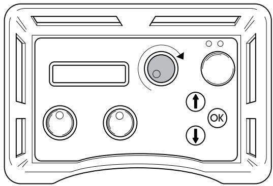
2 Turn the controls for blade rotation and water coolant to their maximum positions to start blade rotation and the water coolant.
The amount of water can be adjusted manually with the knob on the top of the unit.
3 Start the depth feeding by turning the depth feeding knob on the remote control in the desired direction.

4 Start the horizontal motion by turning the horizontal motion knob in the desired direction.
Stopping
1 After the work is completed, turn off the blade rotation and water flow by turning the blade rotation and water coolant start knobs on the remote control back to 0".
2 Turn off the electric motor by pressing the remote control's green button.
Water valve
When the power to the hydraulic unit is disconnected, the water valve opens so that the cooling system can be drained prior to transport and to avoid the risk of the cooler and motor freezing in sub-zero temperatures. The unit can be transported vertically or horizontally. If the power is cut during sawing, the water can be turned off by turning the water flow valve on top of the power unit clockwise to the stop position. The water flow connected to the hydraulic tool can also be reduced by turning the water flow valve.
Dismantling the equipment
1 Allow the motor to stop completely.
2 Disconnect the power supply cable before disconnecting the water hoses.
3 Disconnect the hydraulic hoses.
4 If there is a risk of freezing, drain the water from the oil cooler by disconnecting both hoses, opening the water flow valve, and tilting the unit forwards.
IMPORTANT! Always clean all the equipment at the end of the working day. Do not use a high pressure washer to clean the machine.
Wire cutting
Before starting
IMPORTANT! Do not connect the two thick hydraulic hoses to the wire saw before the cable is correctly fitted and tensioned, and all guards are correctly fitted.
Before you start the motor, check that:
- The incoming electrical cable has been connected to a fuse rated at least 25 A.
- The 32 A or 63 A power setting is chosen. If this is not done, a message in the display will prompt this when the start button is pushed.
- Assemble the pressure reduction block supplied with the wire saw on the hydraulic unit according to the instructions on the block.
- Connect the two smaller hydraulic hoses to the pressure reduction block. The hoses in the hose assembly marked with a red disc by the coupling shall be connected to the hose on the pressure reduction block that is also fitted with a disc.
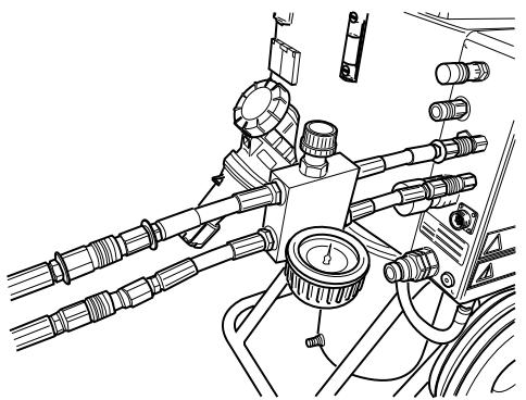
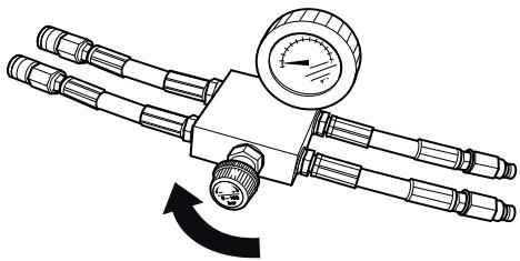
- Close the valve on the pressure reduction block by turning the knob anti-clockwise until it stops and then two turns back.
Starting
1 Start the electric motor by pressing the remote control's green button once.
2 Set the feeding flow on the unit to max by turning the control on the remote control clockwise.
3 Tension the wire by carefully turning the knob on the pressure reduction block clockwise until the wire is tensioned sufficiently. Make sure to always check that the wire is seated correctly in all the wheels on the saw.
4 Start the wire drive by turning the control for motor rotation on the remote control clockwise.
5 Carefully increase the motor speed by turning the control for motor rotation. A suitable working pressure when cutting usually lies between 100 and 130 bar, but varies depending on how many wheel sets are used in the magazine, how much wire is in use and the hardness of the material to be cut.
6 As the material is cut away the working pressure drops, which is shown on the display, and the magazine must then be tensioned. Do this by turning the knob on the pressure reduction block clockwise.
7 The output tension on the magazine is shown by an indicator on the machine (shown in the min position). When the magazine cylinder is fully tensioned, the machine must be stopped and the wire must be wound around a new wheel set. Then continue to cut as above.
Stopping
- Lower the speed on the wire and allow the motor to stop completely.
- Turn off the electric motor by pressing the remote control's green button.
- Disconnect the incoming cables from the hydraulic unit.
- Disconnect the hydraulic hoses and the water hose from the saw unit.
- The other steps are done in the reverse order to assembling.
IMPORTANT! Always clean all the equipment at the end of the working day. Do not use a high pressure washer to clean the machine.
Error messages
Nine different error messages can be shown on the display:
NOTE! LOW VOLTAGE (1A) CHECK THE VOLTAGE SUPPLY AND THE CABLE TO THE HYDRAULIC UNIT
LOW VOLTAGE PHASE X (1B) LOW POWER 32A
MOTOR PROTECTION TRIPPED (2)
- MOTOR OVERHEATED (3) COOLING IN PROGRESS.
DO NOT SWITCH OFF THE ELECTRIC MOTOR
OIL TEMP. HIGH (4) CHECK THE WATER TO THE HYDRAULIC UNIT
- PRESSURE SENSOR OUT OF (5) ORDER
HIGH HYDR PRESSURE (6) CHECK UNIT
- NO CONTACT CHECK THE CAN CABLE (7)
- NO RADIO CONTACT (8)
Error message (1A)
IMPORTANT! Low voltage Check the voltage supply and the cable to the hydraulic unit.
Too low voltage, caused by:
- Long mains cable.
- Too small core size (cross-section) on the mains cable.
One or more phases down, caused by:
- A fuse has blown in the distribution box.
- Cable breakage.
No voltage to one or more phases in the distribution box.
Action (1A)
Press OK to acknowledge the error message.
The hydraulic unit will match the maximum power output to 32 A.
Error message (1B)
Low voltage Phase x low output. 32 A", where x represents phase 1, 2 or 3.
Action (1B)
Press OK to acknowledge the message. It states on the display that the maximum power output is set to 32 A. If the voltage is still low, the electric motor is turned off and the low voltage error message is shown.
By pressing OK, the unit returns to the maximum power you selected at start up. To switch between 63 A and 32 A, the unit must be turned off and then on again.
Read the supply voltage on the operations menu Phase 1, Phase 2, Phase 3". If the voltage, before the motor is started, is:
- Below 340 ~V , check that none of the cores in the cable are broken and that there is voltage up to distribution box.
- Above 340V , check the cable's core dimensions and length.
Error message (2)
Motor protection tripped"
Cause (2)
The electric motor has been overload or a phase is down. This is why the motor cut-out, which is there to protect the electric motor, has tripped.
Action (2)
Press OK to acknowledge the error message. Check that there is voltage to the hydraulic unit on all three phases.
Read the supply voltage on the operations menu Phase 1, Phase 2, Phase 3".
If the voltage to one phase is down: Check the mains cable and the voltage to the distribution box. The motor protection is reset automatically within three minutes.
If the voltage to all phases is higher than 340V : Wait for the motor cut-out to reset. Now restart the hydraulic unit.
If the motor cut-out trips frequently you should call the service personnel.
Error message (3)
Motor overheated cooling in progress. Do not turn off the electric motor!"
IMPORTANT! Do not turn off the motor, as this can damaged it. When the motor has cooled it is turned off automatically.
Cause (3)
The motor temperature sensor is too high.
Action (3)
Press OK to acknowledge the error message.
If after all it is necessary to turn off the engine, the error message must still be acknowledged by first pressing OK.
The display shows: COOLING. The hydraulic valves for blade and trolley motion are turned off. The blade motion can also be restarted.
When the motor temperature sensor drops below the limit level the display shows: MOTOR COOLED PRESS OK.
If the motor frequently overheats you should call the service personnel.
Error message (4)
Oil temp. high Check water to the hydraulic unit"
Cause (4)
Failure to cool the hydraulic oil.
Action (4)
When the error message is shown, the electric motor is turned off. Press OK to acknowledge the error message. Check that the water coolant is connected to the hydraulic unit and that the water runs to the blade when you turn the knob for blade rotation.
Error message (5)
Pressure sensor not working
Cause (5)
The pressure sensor for measuring the hydraulic pressure to the blade rotation is not working.
Action (5)
Press OK to acknowledge the error message. If the error message is shown repeatedly, replace the pressure sensor.
Error message (6)
High hydr pressure check unit"
Cause (6)
The blade has jammed, which causes a high hydraulic pressure.
Action (6)
Press OK to acknowledge the error message. If the error message is shown frequently, you should call the service personnel.
Error message (7)
No contact Check the CAN cable"
Cause (7)
The CAN cable, or its connector is damaged, which results in the hydraulic unit not being possible to control via the remote control.
Action (7)
Press OK to acknowledge the error message. Check the cable and connector and replace if damaged. Contact the service personnel if the fault remains.
Error message (8) - applies to units equipped with a radio system
No radio contact
Cause (8)
The radio contact between the hydraulic unit and remote control is not working.
Action (8)
Several actions may be necessary to rectify the fault:
- Ensure (via the operations menu - settings - radio id) that the identity number is greater than 0.
Make sure that the hydraulic unit has been started. - Move closer to the hydraulic unit to prevent long distances or reinforced walls.
Restart the remote control. Contact the service personnel if the fault remains.
Service
IMPORTANT! All types of repairs may only be carried out by authorised repairmen. This is so that the operators are not exposed to great risks.
After 100 hours of operation, the message "Time for servicing" is displayed. The entire equipment shall then be taken to an authorized Husqvarna dealer for servicing.
Maintenance
IMPORTANT! Inspection and/or maintenance should be carried out with the motor switched off and the plug disconnected.
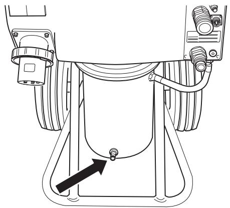
Oil change hydraulic unit
There is a magnetic plug on the underside of the tank for draining the hydraulic fluid. Clean the magnet.

WARNING! Remember that oil can pose a hazard to health and the environment.
Open the screw cap on the tank and fill with hydraulic oil with a viscosity of 68. Make sure that the fluid level is about 10mm below the max. mark on the level indicator.
About 16 litres of hydraulic fluid is required when changing.
Filter replacement
To change the filter, remove the tank cap after loosening the twelve screws. Loosen the three screws for the filter housing cover and remove it as well. Lift out the old filter cartridge and press in the new one, making sure it engages with the end of the tube in the bottom of the housing.
Daily maintenance
Regularly check:
- The hydraulic fluid level in the hydraulic power unit, to make sure it lies between the marks on the level glass.
- Check the tyre pressures.
Any abnormal noises.
PP 455 E
| Specified hydraulic output, kW/hp | 25/33,5 | |
| Max. hydraulic oil flow (at 63 A), l/min / gal/min | 65/17 | |
| Weight hydraulic unit incl. oil, kg/lbs | 140/310 | |
| Power supply | ||
| Europe + Australia 5-pin | 400V (32-63A), 50Hz | |
| Europe + Asia 4-pin | 400V (32-63A), 50Hz | |
| Norway 5-pin | 400V (32-63A), 50Hz | 230V (80A), 50Hz |
| Japan 4-pin | 200V (80A) 50, 60 Hz | |
| USA 4-pin | 480V (63-32A), 60 Hz | |
| Canada 4-pin | 600V (20-40A), 60Hz | |
| Optional equipment | 2 x 230 V wall socket | |
| Noise emissions (see note 1) | ||
| Sound power level, measured dB(A) | 97 | |
| Sound power level, guaranteed dB(A) | 101 | |
| Sound levels (see note 2) | ||
| Sound pressure level at the operators ear, dB(A) | 78 |
IMPORTANT! The higher ampere rating applies for maximum output.
Note 1: Noise emissions in the environment measured as sound power (L_WA) in conformity with EC directive 2000/14/EC.
Note 2: Noise pressure level according to EN ISO 11201. Reported data for noise pressure level has a typical statistical dispersion (standard deviation) of 1.0dB(A)
EC-declaration of conformity
(Appplies to Europe only)
Husqvarna AB, SE-433 81 Göteborg, Sweden, tel: +46-31-949000, declares under sole responsibility that the hydraulic unit Husqvarna PP 455 E from 2010's serial numbers and onwards (the year is clearly stated in plain text on the type plate with subsequent serial number) is in conformity with the requirements of the COUNCIL'S DIRECTIVES:
of May 17, 2006 "relating to machinery" 2006/42/EC
of December 12, 2006 "relating to electrical equipment" 2006/95/EC.
of December 15, 2004 "relating to electromagnetic compatibility" 2004/108/EC.
of May 8, 2000 "relating to the noise emissions in the environment" 2000/14/EC.
The following standards have been applied: EN ISO 12100:2003, EN 55014-1:2006, EN 55014-2/A1:2001, EN 61000-3-11:2000, EN 982/A1:2008, EN 60204-1:2006.
Göteborg December 29, 2009

Henric Andersson
Vice President, Head of Power Cutters and Construction Equipment
Husqvarna AB
(Authorized representative for Husqvarna AB and responsible for technical documentation.)
Simbolos en laquina:
4.4 Drucksens. Hydralik kalibr.
Vice President, Head of Power Cutters and Construction Equipment
Husqvarna AB