FBS-B 13 - Electric sander Mirka - Free user manual and instructions
Find the device manual for free FBS-B 13 Mirka in PDF.

| Product Type | Cordless Electric Belt Sander |
| Brand | Mirka |
| Model | FBS-B 13 |
| Nominal Voltage | 12 VDC |
| Rotational Speed | 2200 to 18000 rpm (adjustable in steps) |
| Belt Speed | 2.5 to 19.6 m/s |
| Belt Dimensions | 13 x 457 mm |
| Weight (tool only) | 0.70 kg |
| Battery Type | Rechargeable Li-ion (compatible with BPA 10825/10850/11125/11150) |
| Battery Voltage | 10.8 to 11.1 VDC |
| Battery Capacity | 2.5 Ah / 27 Wh to 5.0 Ah / 55.5 Wh |
| Charger Included | Mirka BCA 108 (input 100-240 VAC, 50-60 Hz) |
| Charging Time | Less than 50 min (2.5 Ah) / less than 100 min (5.0 Ah) |
| Charger Dimensions | 191 x 102 x 86 mm |
| Charger Weight | 0.66 kg |
| Sound Pressure Level | 72 dB(A) |
| Sound Power Level | 80 dB(A) |
| Vibration Emission Value | 3.125 m/s² |
| Connectivity | Bluetooth Low Energy (MyMirka app) |
| Lighting | Integrated work light angled at 30° |
| Usable Materials | Wood, metal, paint, composite, plastic |
| Safety | Automatic shutdown in case of overheating, battery protection |
| Maintenance | Clean with soft brush, no alcohol or solvent |
| Warranty | Manufacturer: Mirka Ltd, Finland |
Frequently Asked Questions - FBS-B 13 Mirka
User questions about FBS-B 13 Mirka
0 question about this device. Answer the ones you know or ask your own.
Ask a new question about this device
Download the instructions for your Electric sander in PDF format for free! Find your manual FBS-B 13 - Mirka and take your electronic device back in hand. On this page are published all the documents necessary for the use of your device. FBS-B 13 by Mirka.
USER MANUAL FBS-B 13 Mirka
natural_image
Two MIRKA brand push-ups with black and white designs, no visible text or symbols on the devices themselves.
natural_image
Stylized illustration of a bulldog in aggressive posture (no text or symbols)Operating instructions (original)......86en
United States of America, Mexico & Canada
Operating instructions....350us-ca|en
People's Republic of China
zh 操作说明....388
Brazil
Operating instructions......411UK|en
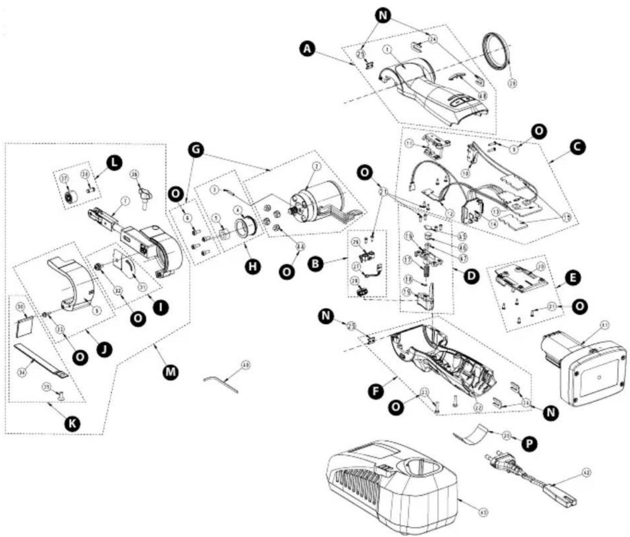
Exploded view
FBS-B 10
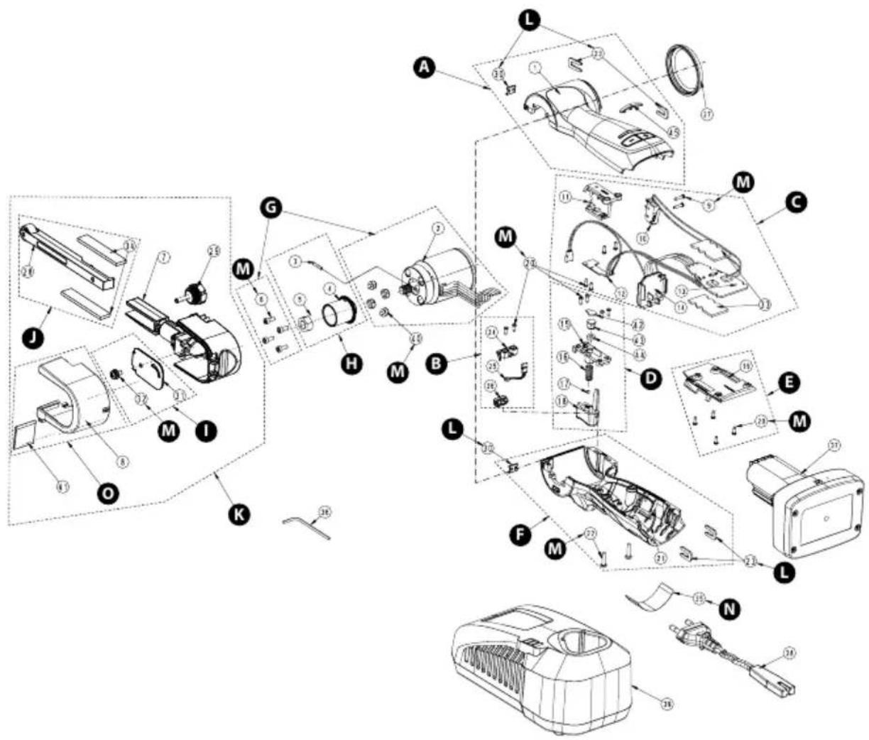
Exploded view
FBS-B 13
Parts list – FBS-B 10 kits
| Quantity Kit Debt expiration torque | |||||
| Upper Housing kitMBB1120111 | |||||
| 1Upper Housing1 | |||||
| 2AAssembly Clamp24 | |||||
| 1Clip25 | |||||
| 1LED Cover48 | |||||
| LED Light kitMBB1122611 | |||||
| 21 | Screw 2,2 x 6,5 mm | 2 | 0,4 Nm/0,3 ft-lb | ||
| 26 | 1BLED Light Holder | ||||
| 27 | 1LED Light Module | ||||
| 28 | 1LED Light Cover | ||||
| MBB1121011 | Speed Controller kit * | ||||
| 9 | Screw 2,2 x 10 mm | 2 | 0,3 Nm/0,2 ft-lb | ||
| 10 | 1Switch | ||||
| 11 | 1Holder | ||||
| 12 | 1CPCB Switch | ||||
| 13 | 1Speed Controller | ||||
| 14 | 1Battery Terminal | ||||
| 15 | 2Cooling Film | ||||
| 21 | Screw 2,2 x 6,5 mm | 4 | 0,4 Nm/0,3 ft-lb | ||
| MBB1121611 | Trigger Button (Variable) kit | ||||
| 16 | 1Trigger Button Cover | ||||
| 1Trigger Spring17 | |||||
| 18 | 1Magnet | ||||
| 19 Trigger Button | 1D | ||||
| 21 | Screw 2,2 x 6,5 mm | 4 | 0,4 Nm/0,3 ft-lb | ||
| 45 | 1Washer | ||||
| 46 | 1Plastic Sleeve | ||||
| 47 | 1Washer | ||||
| 8991022111 | PCB Cover kit | ||||
| PCB Cover20 | 1E | ||||
| 21 | Screw 2,2 x 6,5 mm | 4 | 0,4 Nm/0,3 ft-lb | ||
| Lower Housing kitMBB1122211 | |||||
| 1Lower Housing22 | |||||
| 23 | Screw 2,9 x 13 mm | F | 2 | 0,7 Nm/0,5 ft-lb | |
| 2Assembly Clamp24 | |||||
| 1Clip25 | |||||
| MBB1120211 | Motor kit * | ||||
| 2 | 1Motor | ||||
| 6 | Screw M3 x 8 mm | G | 4 | 1,0 Nm/0,7 ft-lb | |
| 44 | 4Rubber Cap | ||||
| MBB1020311 | Drive Pulley kit | ||||
| 3 | 1Pin | ||||
| 4 Pulley | 1H | ||||
| 5 | 1Nut | ||||
| Quantity Kit Dg b teipirigh item torque | |||||
| Belt Cover kitMBB1023011 | |||||
| 1Side Cover31 | |||||
| 32 | Screw M4 x 8 mm | 1 | 0,9 Nm/0,7 ft-lb | ||
| Guard Cover kitMBB1020811 | |||||
| 1JGuard Cover8 | |||||
| 33 | Screw M3 x 10 mm | 1 | 0,4 Nm/0,3 ft-lb | ||
| Belt Support & Protection kit8995114181 | |||||
| Rubber Shield | 1K | ||||
| 1Belt Support | |||||
| 1Screw M4 x 10 mm | |||||
| MBB1023611 | Rubber Wheel kit | ||||
| Rubber Wheel | 1L | ||||
| Pin | 1 | ||||
| MBB1020711 | File Belt Arm kit | ||||
| 1File Belt Arm 10 mm | |||||
| 1Guard Cover | |||||
| 1Rubber Shield | |||||
| 1Side Cover | |||||
| Screw M4 x 8 mm | M | 1 | 0,9 Nm/0,7 ft-lb | ||
| Screw M3 x 10 mm | 1 | 0,4 Nm/0,3 ft-lb | |||
| 1Belt Support | |||||
| 1Screw M4 x 10 mm | |||||
| 1Wing Screw | |||||
| 1Rubber Wheel | |||||
| Pin | 1 | ||||
| 8991012711 | Assembly Clamp kit | ||||
| Assembly Clamp | 2N | ||||
| 1Clip | |||||
| MBB1120611 | Screw and Rubber Cap kit | ||||
| Screw M3 x 8 mm | 4 | 1,0 Nm/0,7 ft-lb | |||
| Screw 2,2 x 10 mm | 2 | 0,3 Nm/0,2 ft-lb | |||
| Screw 2,2 x 6,5 mm | 14 | 0,4 Nm/0,3 ft-lb | |||
| Screw 2,9 x 13 mm | O | 2 | 0,7 Nm/0,5 ft-lb | ||
| Screw M4 x 8 mm | 1 | 0,9 Nm/0,7 ft-lb | |||
| Screw M3 x 10 mm | 1 | 0,4 Nm/0,3 ft-lb | |||
| 4Rubber Cap | |||||
| MBB1123511 | Type Label kit EU | ||||
| Type Label for FBS-B 10 | P | 10 | |||
| 8991022911US | Type Label kit US/CA | ||||
| Type Label for FBS-B 10 | P | 10 | |||
NOTE! Repairs done by non-authorized repairer will breach the Mirka warranty.
Electrical tools must be serviced by a qualified repair person and in accordance with national requirements.
Parts list – FBS-B 10 spareparts & accessories
| Quantity Kit Debt suspension torque | |||||
| 1AUpper Housing1 | |||||
| 1GMotor2 | |||||
| 1HPin3 | |||||
| 1HPulley4 | |||||
| 1HNut5 | |||||
| 6 | Screw M3 x 8 mm | G,O | 4 | 1,0 Nm/0,7 ft-lb | |
| 7 | File Belt Arm 10 mm | M | 1 | ||
| 8 Guard Cover | 1J,M | ||||
| 9 | Screw 2,2 x 10 mm | C,O | 2 | 0,3 Nm/0,2 ft-lb | |
| 10 1CSwitch | |||||
| 11 1CHolder | |||||
| 12 1CPCB Switch | |||||
| 13 1CSpeed Controller | |||||
| 14 1CBattery Terminal | |||||
| 8991213111 15 CCooling Film 2 pcs/pack | |||||
| 16 1DTrigger Button Cover | |||||
| 1DTrigger Spring17 | |||||
| 18 1DMagnet | |||||
| 19 1DTrigger Button | |||||
| 20 PCB Cover | 1E | ||||
| 21 | Screw 2,2 x 6,5 mm | B,C,D,E,O | 14 | 0,4 Nm/0,3 ft-lb | |
| Lower Housing22 | 1F | ||||
| 23 | Screw 2,9 x 13 mm | F,O | 2 | 0,7 Nm/0,5 ft-lb | |
| 24 Assembly Clamp | 2A,F,N | ||||
| 25 | Clip | A,F,N | |||
| 26 LED Light Holder | 1B | ||||
| 27 LED Light Module | 1B | ||||
| 28 LED Light Cover | 1B | ||||
| MBB1112911 | 29 | Rubber Cover | 1 | ||
| 1K,MRubber Shield30 | |||||
| 311,MSide Cover | |||||
| 32 | Screw M4 x 8 mm | I,M,O | 1 | 0,9 Nm/0,7 ft-lb | |
| 33 | Screw M3 x 10 mm | J,M,O | 1 | 0,4 Nm/0,3 ft-lb | |
| 34K,MBelt Support | |||||
| 35 | Screw M4 x 10 mm | K,M | 1 | ||
| MBB1013611 | 36 | Wing Screw | M | 1 | |
| Rubber Wheel37 | 1L,M | ||||
| Pin38 | 1L,M | ||||
| 39 | Type Label for FBS-B 10 | P | 1 | ||
| 8995121314 | 40 | Hex Wrench 2 & 3mm | 1 | ||
| 8991122211 | 41 | Mirka Intelligent Battery BPA 11125 11.1V 2.5Ah | 1 | ||
| 8991122311 | 41 | Mirka Intelligent Battery BPA 11150 11.1V 5.0Ah | 1 | ||
| 8991112211 | 42 | Power Cord 2.0 m EU | 1 | ||
| 8991112311 | 42 | Power Cord 2.0 m US | 1 | ||
| Quantity Kit Dg Is teipirign Item torque | |||
| 1Power Cord 2.0 m UK42899111241 | |||
| 1Power Cord 2.0 m CN42899111261 | |||
| 1Power Cord 2.0 m ANZ4289911127 | |||
| 1Battery Charger438991123011 | |||
| 1Battery Charger (North America)43 | |||
| 4G,ORubber Cap44 | |||
| 1DWasher45 | |||
| 1DPlastic Sleeve46 | |||
| 1DWasher47 | |||
| 48 1ALED Cover | |||
* Spare parts only available to authorized repairers.
Parts list – FBS-B 13 kits
| Quantity Kit Debt expiration torque | |||||
| Upper Housing kitMBB1120111 | |||||
| 1Upper Housing1 | |||||
| 2AAssembly Clamp23 | |||||
| 1Clip30 | |||||
| 1LED Cover45 | |||||
| LED Light kitMBB1122611 | |||||
| 20 | Screw 2,2 x 6,5 mm | 2 | 0,4 Nm/0,3 ft-lb | ||
| 24 | 1BLED Light Holder | ||||
| 25 | 1LED Light Module | ||||
| 26 | 1LED Light Cover | ||||
| MBB1121011 | Speed Controller kit * | ||||
| 9 | Screw 2,2 x 10 mm | 2 | 0,3 Nm/0,2 ft-lb | ||
| 10 | 1Switch | ||||
| 11 | 1Holder | ||||
| 12 | 1CPCB Switch | ||||
| 13 | 1Speed Controller | ||||
| 14 | 1Battery Terminal | ||||
| 20 | Screw 2,2 x 6,5 mm | 4 | 0,4 Nm/0,3 ft-lb | ||
| 33 | 2Cooling Film | ||||
| MBB1121611 | Trigger Button (Variable) kit | ||||
| 15 | 1Trigger Button Cover | ||||
| 1Trigger Spring16 | |||||
| 17 | 1Magnet | ||||
| 18 Trigger Button | 1D | ||||
| 20 | Screw 2,2 x 6,5 mm | 4 | 0,4 Nm/0,3 ft-lb | ||
| 42 | 1Washer | ||||
| 43 | 1Plastic Sleeve | ||||
| 44 | 1Washer | ||||
| 8991022111 | PCB Cover kit | ||||
| PCB Cover19 | 1E | ||||
| 20 | Screw 2,2 x 6,5 mm | 4 | 0,4 Nm/0,3 ft-lb | ||
| Lower Housing kitMBB1122211 | |||||
| 1Lower Housing21 | |||||
| 22 | Screw 2,9 x 13 mm | F | 2 | 0,7 Nm/0,5 ft-lb | |
| 2Assembly Clamp23 | |||||
| 1Clip30 | |||||
| MBB1120211 | Motor kit * | ||||
| 2 | 1Motor | ||||
| 6 | Screw M3 x 8 mm | G | 4 | 1,0 Nm/0,7 ft-lb | |
| 40 | 4Rubber Cap | ||||
| MBB1320311 | Drive Pulley kit | ||||
| 3 | 1Pin | ||||
| 4 Pulley | 1H | ||||
| 5 | 1Nut | ||||
| Quantity Kit Debt to replicate torque | |||||
| Belt Cover kitMBB1323111 | |||||
| 1Side Cover31 | |||||
| 32 | Screw M4 x 8 mm | 1 | 0,9 Nm/0,7 ft-lb | ||
| Adjusting Arm kit8995144101 | |||||
| 1JAdjusting Arm Assembly28 | |||||
| 2Wear Pad34 | |||||
| File Belt Arm kitMBB1320711 | |||||
| 7 | File Belt Arm 13 mm | 1 | |||
| 8 | 1Guard Cover | ||||
| 1Adjusting Arm Assembly28 | |||||
| 29 | Angle Adjusting Bolt | K | 1 | ||
| 1Side Cover31 | |||||
| 32 | Screw M4 x 8 mm | 1 | 0,9 Nm/0,7 ft-lb | ||
| 2Wear Pad34 | |||||
| 1Rubber Shield41 | |||||
| 8991012711 | Assembly Clamp kit | ||||
| 23 Assembly Clamp | 2L | ||||
| 30 | 1Clip | ||||
| MBB1120611 | Screw and Rubber Cap kit | ||||
| 6 | Screw M3 x 8 mm | 4 | 1,0 Nm/0,7 ft-lb | ||
| 9 | Screw 2,2 x 10 mm | 2 | 0,3 Nm/0,2 ft-lb | ||
| 20 | Screw 2,2 x 6,5 mm | M | 14 | 0,4 Nm/0,3 ft-lb | |
| 22 | Screw 2,9 x 13 mm | 2 | 0,7 Nm/0,5 ft-lb | ||
| 32 | Screw M4 x 8 mm | 1 | 0,9 Nm/0,7 ft-lb | ||
| 40 | 4Rubber Cap | ||||
| MBB1123511 | Type Label kit EU | ||||
| 35 | Type Label for FBS-B 13 | N | 10 | ||
| 8991022911US | Type Label kit US/CA | ||||
| 35 | Type Label for FBS-B 13 | N | 10 | ||
| MBB1320811 | Guard Cover & Rubber Shield kit | ||||
| 8 Guard Cover | 10 | ||||
| 1Rubber Shield41 | |||||
NOTE! Repairs done by non-authorized repairer will breach the Mirka warranty.
Electrical tools must be serviced by a qualified repair person and in accordance with national requirements.
Parts list – FBS-B 13 spareparts & accessories
| Quantity Kit Debt suspension torque | |||||
| 1AUpper Housing1 | |||||
| 1GMotor2 | |||||
| 1HPin3 | |||||
| 1HPulley4 | |||||
| 1HNut5 | |||||
| 6 | Screw M3 x 8 mm | G,M | 4 | 1,0 Nm/0,7 ft-lb | |
| 7 | File Belt Arm 13 mm | K | 1 | ||
| 8 Guard Cover | 1K,O | ||||
| 9 | Screw 2,2 x 10 mm | C,M | 2 | 0,3 Nm/0,2 ft-lb | |
| 10 1CSwitch | |||||
| 11 1CHolder | |||||
| 12 1CPCB Switch | |||||
| 13 1CSpeed Controller | |||||
| 14 1CBattery Terminal | |||||
| 15 1DTrigger Button Cover | |||||
| 1DTrigger Spring16 | |||||
| 17 1DMagnet | |||||
| 18 1DTrigger Button | |||||
| 19 PCB Cover | 1E | ||||
| 20 | Screw 2,2 x 6,5 mm | B,C,D,E,M | 14 | 0,4 Nm/0,3 ft-lb | |
| Lower Housing21 | 1F | ||||
| 22 | Screw 2,9 x 13 mm | F,M | 2 | 0,7 Nm/0,5 ft-lb | |
| 23 Assembly Clamp | 2A,F,L | ||||
| 24 LED Light Holder | 1B | ||||
| 25 LED Light Module | 1B | ||||
| 26 LED Light Cover | 1B | ||||
| MBB1112911 | 27 | Rubber Cover | 1 | ||
| 28 | Adjusting Arm Assembly | J,K | 1 | ||
| 29 | Angle Adjusting Bolt | K | 1 | ||
| 30 Clip | 1A,F,L | ||||
| 31 Side Cover | 1I,K | ||||
| 32 | Screw M4 x 8 mm | I,K,M | 1 | 0,9 Nm/0,7 ft-lb | |
| 8991213111 33 CCooling Film 2 pcs/pack | |||||
| 8995134111 34J,KWear Pad2 | |||||
| 35 | Type Label for FBS-B 13 | N | 1 | ||
| 8995121314 | 36 | Hex Wrench 2 & 3mm | 1 | ||
| 8991122211 | 37 | Mirka Intelligent Battery BPA 11125 11.1V 2.5Ah | 1 | ||
| 8991122311 | 37 | Mirka Intelligent Battery BPA 11150 11.1V 5.0Ah | 1 | ||
| 8991112211 | 38 | Power Cord 2.0 m EU | 1 | ||
| 8991112311 | 38 | Power Cord 2.0 m US | 1 | ||
| 8991112411 | 38 | Power Cord 2.0 m UK | 1 | ||
| 8991112611 | 38 | Power Cord 2.0 m CN | 1 | ||
| 8991112711 | 38 | Power Cord 2.0 m ANZ | 1 | ||
| 8991123011 | 39 | Battery Charger | 1 | ||
| Quantity Kit Dg bclspirign item torque | |||
| 1Battery Charger (North America)39 | |||
| 4G,MRubber Cap40 | |||
| 1K,ORubber Shield41 | |||
| 1DWasher42 | |||
| 1DPlastic Sleeve43 | |||
| 1DWasher44 | |||
| 1ALED Cover45 | |||
* Spare parts only available to authorized repairers.
| Mirka Ltd, 66850 Jeppo, FinlandEN:En 301 489- و EN 300 328 V2.2.2 و EN 55014-2:2021 و EN 55014-1:2021 و EN 62841-2-4:2014+AC:2015 و 62841-1:2015+AC:2015+A11:2022ممتّل شاحن 2012/19/EU و 2015/863/EU و 2011/65/EU و/EU2014/53 و 2006/42/EC وفقاً للوانح EN IEC 63000:2018 و EN 301 489-17 V3.2.4 و 1 V2.2.3 EN 55014- و EN 55014-1:2017 و EN 62233:2008 و EN 60335-2-29:2021/A1:2021 و EN 60335-1:2012/A15:2021البطارية للمعابير والتجيهات التالية; EN 55014- و EN 55014-1:2017 و EN 62233:2008 و EN 60335-2-29:2021/A1:2021 و EN 60335-1:2012/A15:20212015/863/EU و/EU2011/65 و 2014/30/EU و/7EU2014/35 و وفقاً للوانح EN IEC 63000:2018 و EN 61000-3-3:2013 و EN 61000-3-2:2014 و 2:2015/7EU2012/19 | ||||
| FBS-B 10 & 13 °Mirka :المتجات | ||||
 | المصنع / المورد:Mirka LtdJeppo, Finland 66850+358 20 760 2111 هانف: +358 20 760 2290 فاكس:www.mirka.com | 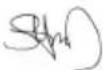 -ستيفين سيوبيرج،ический التفيفيسي -ستيفين سيوبيرج،ический التفيفيسي |  الشركة الشركة | Jeppo 01.02.2024مكان وتاريخ الإصدار |
ت Connectivity Marketing Goal: En Exposure to the Most of the Most of the Most of the Most of the Most of the Most of the Most of the Most of the Most of the Most of the Most of the Most of the Most of the Most of the Most of the Most of the Most of the Most of the Most of the Most of the Most of the Most of the Most of the Most of the Most of the Most of the Most of the Most of the Most of the Most of the Most of the Most of the Most of the Most of
البيانات الفنية

Remain continuously on

Flashing
تشخيصات الشاحن
سيشیر الشاحن إلى:
natural_image
Line drawing of a padlock with an open lock and a switch, no text or symbols present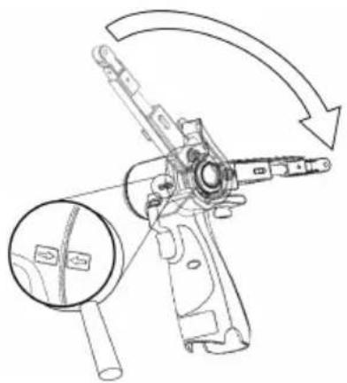
natural_image
Technical line drawing of a mechanical device with an arrow indicating rotation or assembly (no text or symbols present)natural_image
Technical line drawing of a mechanical device with a lock and handle, no text or symbols present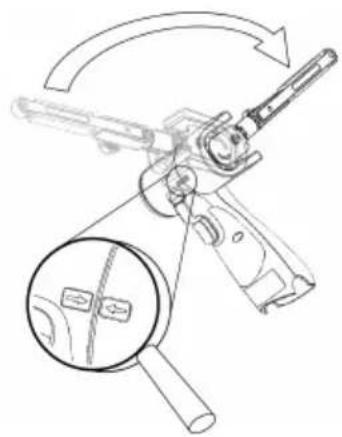
natural_image
Diagram of a firearm with magnified inset showing internal components (no text or labels)natural_image
Technical line drawing of a mechanical lever assembly with no visible text or symbols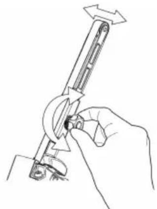
natural_image
Line drawing of a hand holding a tool with directional arrows indicating movement (no text or symbols)natural_image
Line drawing of a device's internal components, showing a handle, grip, and lever assembly (no text or symbols)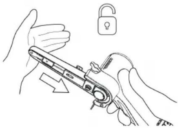
natural_image
Line drawing of hands holding a mechanical device with an open lock icon (no text or symbols)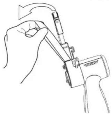
natural_image
Line drawing of a hand using a tool to adjust or install a mechanical component (no text or symbols present)natural_image
Line drawings showing hands using a tool to adjust or install a mechanical component, with no visible text or symbols.التنظيف
| LED | ||||||
| 3 | ||||||
| 2 | ||||||
| 1 |  | |||||
| Status | Pre-charge(Trickle charge) | Charging... | Charging... | Charging finished | Over temperature | Battery failure |

Remain continuously on

Flashing
natural_image
Line drawing of a hand holding a lock and a padlock, with no text or symbols presentnatural_image
Technical line drawing of a mechanical tool with an arrow indicating rotational motion (no text or symbols present)natural_image
Technical line drawing of a firearm with magnified inset showing internal components (no text or symbols)natural_image
Line drawing of a handheld device with a light bulb above it, no text or symbols presentnatural_image
Technical line drawing of a mechanical device with internal components (no text or symbols)Извадетебатерията.

natural_image
Illustration showing two-step manual techniques for adjusting a mechanical device, with no text or symbols present.Натиснетеобтягашоторамокъмстоманениязащитен капак, задаосвободитеблокиращатафункция.
natural_image
Line drawings showing two hands using a tool to adjust or install a mechanical component (no text or symbols present)Извадетебатерията.
natural_image
Symbol of a trash bin with crossed lines indicating no waste or discharge (no text or labels)| LED | |
 | |
 Remain continuously on Remain continuously on |  Flashing Flashing |
Remain continuously on
Flashing
Diagnostika nabíječky
Nabíječka indikuje tyto stavy:
natural_image
Technical line drawing showing two mechanical assembly steps: one with a lever mechanism and arrow indicating direction, the other with a hand holding a tool (no text or symbols present)natural_image
Line drawing of a handheld device with a light bulb above it, no text or symbols presentnatural_image
Technical line drawing of a mechanical device with internal components (no text or symbols)Vyjměte baterii.

natural_image
Line drawing of hands using a tool to adjust a lock, with an open padlock symbol nearby (no text or labels)
natural_image
Line drawing of a hand using a tool to adjust or install a component, no text or symbols presentnatural_image
Line drawing of a mechanical device with internal components and a handle (no text or symbols)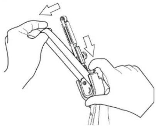
natural_image
Line drawing of hands using a tool to adjust or install a mechanical component, with arrows indicating direction (no text or symbols)Vyjměte baterii.
natural_image
Symbol of a trash bin with crossed lines indicating no waste or discharge, and a solid black rectangle below (no text or labels)natural_image
Technical line drawing showing two mechanical assembly steps: one with a lever mechanism and the other with a hand holding a tool (no text or symbols present)natural_image
Line drawing of a handheld device with a light bulb above it, no text or symbols presentnatural_image
Technical line drawing of a mechanical device with internal components (no text or symbols)Fjern batteriet.

natural_image
Illustration showing two-step manual techniques for adjusting a mechanical device, with no text or symbols present.natural_image
Line drawings showing two hands using a tool to adjust or install a mechanical component (no text or symbols present)Fjern batteriet.
natural_image
Symbol of a trash bin with crossed lines indicating no waste or discharge, and a solid black rectangle below (no text or labels)| LED | ||||||
| 3 | ||||||
| 2 | ||||||
| 1 | ||||||
| Status | Pre-charge (Trickle charge) | Charging... | Charging... | Charging finished | Over temperature | Battery failure |

Remain continuously on

Flashing
natural_image
Technical line drawing of a mechanical device with a lock and lever mechanism (no text or symbols)
natural_image
Technical line drawing of a mechanical device with a magnified inset showing internal components (no text or symbols)natural_image
Technical line drawing of a mechanical lever assembly with directional arrows indicating motion (no text or symbols)
natural_image
Line drawing of a hand using a tool to adjust or install a mechanical component (no text or symbols present)natural_image
Line drawing of a handheld electric shaver with a light bulb icon above it (no text or symbols)natural_image
Line drawing of a mechanical device with internal components (no text or symbols)Akku entfernen.

natural_image
Line drawing of hands holding a tool with an open padlock icon (no text or symbols)natural_image
Line drawing of a hand holding a mechanical device with a tool, no text or symbols presentnatural_image
Line drawing of a mechanical device with internal components and adjustment knobs (no text or symbols)Akku entfernen.

natural_image
Line drawing of hands using a tool to adjust or install a mechanical component, with arrows indicating motion (no text or symbols)natural_image
Symbol of a trash bin with crossed lines and a solid rectangle below (no text or labels)| LED | ||||||
| 3 | ||||||
| 2 | ||||||
| 1 |  | |||||
| Status | Pre-charge(Trickle charge) | Charging... | Charging... | Charging finished | Over temperature | Battery failure |
natural_image
Line drawing of a hand holding a device with an open padlock icon (no text or symbols)natural_image
Technical line drawing of a mechanical tool with an arrow indicating rotational motion (no text or symbols present)natural_image
Technical line drawing of a firearm with an inset magnified view showing internal components (no text or symbols)natural_image
Technical line drawing showing two mechanical assembly steps: one with a lever mechanism and the other with a hand holding a tool (no text or symbols present)natural_image
Line drawing of a handheld device with a light bulb above it, no text or symbols presentnatural_image
Technical line drawing of a mechanical device with internal components (no text or symbols)natural_image
Illustration showing two-step manual techniques for adjusting a mechanical device, with no text or symbols present.natural_image
Line drawings showing two hands using a tool to adjust or install a mechanical component, with arrows indicating the process (no text or symbols present)natural_image
Symbol of a trash bin with crossed lines indicating no waste or discharge, and a solid black rectangle below (no text or labels)Declaration of conformity
Mirka Ltd, 66850 Jeppo, Finland
declare under our sole responsibility that the Mirka® products (listed below and see "Technical data" table for particular model) to which this declaration relates are in conformity with the following standards or other normative documents: EN 62841-1:2015+AC:2015+A11:2022, EN 62841-2-4:2014+AC:2015, EN 55014-1:2021, EN 55014-2:2021, EN 300 328 V2.2.2, EN 301 489-1 V2.2.3, EN 301 489-17 V3.2.4 & EN IEC 63000:2018 in accordance with the regulations 2006/42/EC, 2014/53/EU, 2011/65/EU, 2015/863/EU & 2012/19/EU. The battery charger are in conformity with the following standards and directives; EN 60335-1:2012/A15:2021, EN 60335-2-29:2021/A1:2021, EN 62233:2008, EN 55014-1:2017, EN 55014-2:2015, EN 61000-3-2:2014, EN 61000-3-3:2013 & EN IEC 63000:2018 in accordance with the regulations 2014/35/EU, 2014/30/EU, 2011/65/EU, 2015/863/EU & 2012/19/EU.
Products: Mirka® FBS-B 10 & 13
Jeppo 01.02.2024
Place and date of issue

Manufacturer/Supplier
Mirka Ltd
66850 Jeppo, Finland
Tel.+358 20 760 2111
Fax +358 20 760 2290
www.mirka.comStefan Sjöberg, CEOCompany

Original instructions. We reserve the right to make changes to this manual without prior notice.
Important
Read these safety and operating instructions carefully before installing, operating or maintaining this tool. Keep these instructions in a safe and accessible place. Read and comply with state and local regulations.
Note: Mirka products are in continuous development. Please visit mirka.com for the latest version of these instructions.
Required personal safety equipment

Read operator's manual

Wear safety glasses

Wear
ear protection

Wear safety gloves

Wear face mask
Symbols
 | Complies with EU relevant standards |
 | Complies with UK relevant regulations |
 | Complies with China RoHS requirement |
 | Complies with Australia & New Zealand RCM requirement |
 | Complies with Eurasian conformity requirements |
 | Complies with Brazilian conformity requirements |

Warning: Potential hazardous situation that may result in death or serious injury and/or property damage. Caution: Potential hazardous situation that may result in minor or moderate injury and/or property damage.

General Power Tool Safety Warnings

WARNING Read all safety warnings and all instructions. Failure to follow the warnings and instructions may result in electric shock, fire and/or serious injury. Save all warnings and instructions for future reference. The term “power tool” in the warnings refers to your mains-operated (corded) power tool or battery-operated (cordless) power tool.
1. Work area safety
a. Keep work area clean and well lit. Cluttered or dark areas invite accidents.
b. Do not operate power tools in explosive atmospheres, such as in the presence of flammable liquids, gases or dust. Power tools create sparks which may ignite the dust or fumes.
c. Keep children and bystanders away while operating a power tool. Distractions can cause you to lose control.
2. Electrical safety
a. Power tool plugs must match the outlet. Never modify the plug in any way. Do not use any adapter plugs with earthed (grounded) power tools. Unmodified plugs and matching outlets will reduce risk of electric shock.
b. Avoid body contact with earthed or grounded surfaces, such as pipes, radiators, ranges and refrigerators. There is an increased risk of electric shock if your body is earthed or grounded.
c. Do not expose power tools to rain or wet conditions. Water entering a power tool will increase the risk of electric shock.
d. Do not abuse the cord. Never use the cord for carrying, pulling or unplugging the power tool. Keep cord away from heat, oil, sharp edges and moving parts. Damaged or entangled cords increase the risk of electric shock.
e. When operating a power tool outdoors, use an extension cord suitable for outdoor use. Use of a cord suitable for outdoor use reduces the risk of electric shock.
f. If operating a power tool in a damp location is unavoidable, use a residual current device (RCD) protected supply. Use of an RCD reduces the risk of electric shock.
3. Personal safety
a. Stay alert, watch what you are doing and use common sense when operating a power tool. Do not use a power tool while you are tired or under the influence of drugs, alcohol or medication. A moment of inattention while operating power tools may result in serious personal injury.
b. Use personal protective equipment. Always wear eye protection. Protective equipment such as a dust mask, non-skid safety shoes, hard hat, or hearing protection used for appropriate conditions will reduce personal injuries.
c. Prevent unintentional starting. Ensure the switch is in the off-position before connecting to power source and/or battery pack, picking up or carrying the tool. Carrying power tools with your finger on the switch or plugging in tools when the switch is in the on-position invites accidents.
d. Remove any adjusting key or wrench before turning the power tool on. A wrench or a key left attached to a rotating part of the power tool may result in personal injury.
e. Do not overreach. Keep proper footing and balance at all times. This enables better control of the power tool in unexpected situations.
f. Dress properly. Do not wear loose clothing or jewellery. Keep your hair, clothing and gloves away from moving parts. Loose clothes, jewellery or long hair can be caught in moving parts.
g. If devices are provided for the connection of dust extraction and collection facilities, ensure these are connected and properly used. Use of dust collection can reduce dust-related hazards.
h. Do not let familiarity gained from frequent use of tools allow you to become complacent and ignore tool safety principles. A careless action can cause severe injury within a fraction of a second.
4. Power tool use and care
a. Do not overload the power tool. Use the correct power tool for your application. The correct power tool will do the job better and safer at the rate for which it was designed.
b. Do not use the power tool if the switch does not turn it on and off. Any power tool that cannot be controlled with the switch is dangerous and must be repaired.
c. Disconnect the plug from the power source and/or the battery pack from the power tool before making any adjustments, changing accessories, or storing power tools. Such preventive safety measures reduce the risk of starting the power tool accidentally.
d. Store idle power tools out of the reach of children and do not allow persons unfamiliar with the power tool or these instructions to operate the power tool. Power tools are dangerous in the hands of untrained users.
e. Maintain power tools and accessories. Check for misalignment or binding of moving parts, breakage of parts and any other condition that may affect the power tool's operation. If damaged, have the power tool repaired before use. Many accidents are caused by poorly maintained power tools.
f. Keep cutting tools sharp and clean. Properly maintained cutting tools with sharp cutting edges are less likely to bind and are easier to control.
g. Use the power tool, accessories and tool bits etc. in accordance with these instructions, taking into account the working conditions and the work to be performed. Use of the power tool for operations different from those intended could result in a hazardous situation.
h. Keep handles and grasping surfaces dry, clean and free from oil and grease. Slippery handles and grasping surfaces do not allow for safe handling and control of the tool in unexpected situations.
5. Battery tool use and care
a. Recharge only with the charger specified by the manufacturer. A charger that is suitable for one type of battery pack may create a risk of fire when used with another battery pack.
b. Use power tools only with specifically designated battery packs. Use of any other battery packs may create a risk of injury and fire.
c. When battery pack is not in use, keep it away from other metal objects, like paper clips, coins, keys, nails, screws or other small metal objects, that can make a connection from one terminal to another. Shorting the battery terminals together may cause burns or a fire.
d. Underabusive conditions, liquid may be ejected from the battery; avoid contact. If contact accidentally occurs, flush with water. If liquid contacts eyes, additionally seek medical help. Liquid ejected from the battery may cause irritation or burns.
e. Do not use a batter pack or tool that is damaged or modified. Damaged or modified batteries may exhibit unpredictable behaviour resulting in fire, explosion or risk of injury.
f. Do not expose a battery pack or tool to fire or excessive temperature. Exposure to fire or temperature above 130 °C may cause explosion.
g. Follow all charging instructions and do not charge the battery pack or tool outside the temperature range specified in the instructions. Charging improperly or at temperatures outside the specified range may damage the battery and increase the risk of fire.
6. Service
a. Have your power tool serviced by a qualified repair person using only identical replacement parts. This will ensure that the safety of the power tool is maintained.
b. Never service damaged battery packs. Service of battery packs should only be performed by the manufacturer or authorized service providers

Safety rules for battery pack and charger
- Important safety and operating instructions for your battery and charger. Before using the charger, read all instructions and warnings on the charger, the battery pack and the tool.
- If the battery pack casing is cracked or damaged, do not insert into charger. There is a danger of electric shock or electrocution.
- Do not allow any liquid to get inside charger. Electric shock may result.
- This charger is not intended for any uses other than charging rechargeable batteries.
- Do not place any object on top of the charger, near any heat source or place the charger on a soft surface that may result in excessive internal heat.
- Make sure the cord is located so it will not be stepped on, tripped over, or otherwise subjected to damage or stress.
- Do not use the charger if it has received a sharp blow, been dropped or otherwise damaged in any way.
- Do not store or use the tool and battery pack in locations where the temperature may reach or exceed 50^ (122°F).
- The charger is designed to operate on standard household electrical power (100–240 VAC). Do not attempt to use it on any other voltage.
- Children should be supervised to ensure that they do not play with the appliance.

Additional Safety Warnings
• Always ensure that the work piece to be sanded is firmly fixed in place.
• Always remove battery during any transportation of the tool.
- Do not allow the tool to free speed without taking precautions to protect surrounding people and objects in the event that the abrasive or other moving parts should come loose.
- Read all instructions before using this tool. All operators must be fully trained in the proper, safe use of this tool.
- All maintenance must be carried out by trained personnel. For service, contact a Mirka authorized service center.
- If the tool appears to malfunction, stop using it immediately and arrange for service and repair.
- Before changing the abrasive always disconnect the power source
- Never carry, store or leave the tool unattended with the power source connected.
- Keep hands clear of the abrasive belt during use.
- Always wear required personal safety protection in accordance with manufacturer's instructions and local/national standards while using this tool.
- Read the Materials Safety Data Sheet (MSDS) for the working surface.
- If any physical hand/wrist discomfort is experienced, stop working and seek medical attention. Hand, wrist and arm injury may result from repetitive work, motion and overexposure to vibrations.
Additional information on battery and charger
- Never attempt to open the battery pack for any reason. If the plastic housing of the battery pack breaks or cracks, immediately discontinue use and do not recharge.

Additional Warnings
Some dust created by power sanding, sawing, grinding, drilling, and other construction activities contains chemicals known to cause cancer, birth defects or other reproductive harm. Some examples of these chemicals are:
- lead from lead-based paints,
• crystalline silica from bricks and cement and other masonry products, and
• arsenic and chromium from chemicallytreated lumber.
Your risk from these exposures varies, depending on how often you do this type of work. To reduce your exposure to these chemicals: work in a well ventilated area, and work with approved safety equipment, such as those dust masks that are specially designed to filter out microscopic particles.
Technical data
| * | FBS-B 13FBS-B 10Mirka | |
| 12 VDC12 VDCVoltage | ||
| Speed | 2200 –18000 rpm | 2200 –18000 rpm |
| Weight (tool only) | 0.70 kg (1.5 lbs) | 0.74 kg (1.6 lbs) |
| Belt size | 10 x 330 mm(3/8" x 13" ") | 13 x 457 mm(1/2" x 18" ") |
| Belt speed | 2.6 – 20.5 m/s | 2.5 – 19.6 m/s |
| Mirka BCA 108Battery charger | |
| Input | 100-240 VAC, 50-60Hz |
| Charging time | < 50 min (2.5 Ah)< 100 min (5.0 Ah) |
| Storage temperature range | -20 °C - 80 °C (-4 °F - 176 °F) |
| Charging temperature | 4 °C - 40 °C (39 °F - 104 °F) |
| Dimension | 191 x 102 x 86 mm(7 1/2" x 4" x 3 3/8" ")0.66 kg (1.5 lbs)Weight |
| II /Degree of protection |
| Battery pack | Mirka BPA 10825 | Mirka BPA 10850 | Mirka BPA 11125 | Mirka BPA 11150 |
| RechargeableRechargeableRecharge Li-ionLi-ionLi-ionLi-ion | ||||
| Battery voltage | 10.8 VDC | 10.8 VDC | 11.1 VDC | 11.1 VDC |
| Capacity | 2.5 Ah / 27.0 Wh | 5.0 Ah / 54.0 Wh | 2.5 Ah / 27.75 Wh | 5.0 Ah / 55.5 Wh |
| Weight | 0.18 kg (0.4 lbs) | 0.38 kg (0.8 lbs) | 0.18 kg (0.4 lbs) | 0.38 kg (0.8 lbs) |
| YesYesYesYesIntelligent battery |
Noise and vibration information
The measured values may be used for comparing one tool with another and in a preliminary assessment of exposure.
| FBS-B 13FBS-B 10Cordless | ||
| Sound pressure level (LpA) | 72.0 dB(A) | 72.0 dB(A) |
| Sound power level (LWR) | 80.0 dB(A) | 80.0 dB(A) |
| Sound measurement uncertainty KWA | 3.0 dB(A) | 3.0 dB(A) |
| Vibration emission value ah* | 3.125 m/s2 | 3.125 m/s2 |
| Vibration emission uncertainty KPA* | 1.5 m/s2 | 1.5 m/s2 |
Specifications subject to change without prior notice. Model range may vary between markets.
* The values stated in the table are derived from laboratory testing in conformity with stated codes and standards and are not sufficient for risk evaluation. Values measured in a particular work place may be higher than the declared values. The actual exposure values and amount of risk or harm experienced by an individual are unique to each situation and depend upon the surrounding environment, the way the individual operates the machinery, the particular material being worked, work station design and the user's exposure time and physical condition. Mirka accepts no responsibility for the consequences of using declared values instead of actual exposure values for any individual risk assessment.
Further occupational health and safety information can be obtained from the following websites:
https://osha.europa.eu/en (Europe) or http://www.osha.gov (USA)
Proper use of tool
This sander is designed for sanding all types of materials such as paints, metals, wood, composites, plastics, etc., using abrasives specially designed for this purpose. Do not use this sander for any other purpose than that specified without consulting the manufacturer or the manufacturer's authorized supplier. Any maintenance or repair work requiring the motor housing to be opened may only be carried out by an authorized service center.
Battery and charger
- The battery pack is not fully charged out of the carton. First read the safety instructions and then charge your battery according to the instructions.
- For optimal charging capacity the battery should be charged at an ambient temperature between 18 °C (64 °F) and 24 °C (75 °F). To prevent damage to the battery pack, do not charge the battery pack where the air temperature is below 4 °C (39 °F) or above 40 °C (104 °F).
• To obtain the longest possible battery life, we suggest the following:
- Store and charge your battery in a cool area. Temperatures above or below normal room temperature will shorten battery life.
- Never store the battery in a discharged condition. Recharge it immediately after it has been discharged.
• All batteries gradually lose their charge. The higher the temperature, the quicker they lose their charge.
If you store your tool for long periods of time without use, recharge the battery every month. This practice will prolong battery life.
Charging procedure
- Connect the power cord to the charger, and then plug into an outlet before inserting battery pack. All three charging lights will be on for two seconds and then turn off.
- Insert the battery pack into the charger. The lights will start to flash within 30 seconds.
- During the charging process, the charging lights will indicate the status as follows:
- Three charging lights will flash in sequence during the charging process.
– Fully charged, all three lights will remain on continuously.
- The charging process will last approximately 50 minutes for BPA 10825/11125 and 100 minutes for BPA 10850/11150 battery pack.
NOTE! This charger can only charge Mirka 12V battery packs.
NOTE! Charging times may be longer depending on the surrounding temperature and battery conditions.
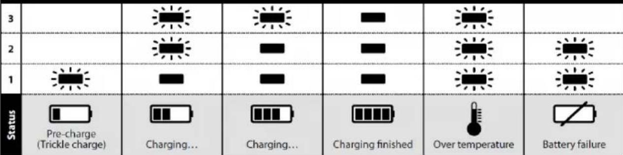
LED indication of BCA 108 charger
| LED | ||||||
| 3 | ||||||
| 2 | ||||||
| 1 | ||||||
| Status | Pre-charge(Trickle charge) | Charging... | Charging... | Charging finished | Over temperature | Battery failure |

Remain continuously on

Flashing
Charger diagnostics
The charger will indicate if:
- A battery pack is overheated. All three charging lights will flash. Remove the battery and allow it to cool down for 15–30 minutes and re-insert.
- A malfunction occurs in the battery or the charger. Two charging lights will flash. Remove the battery and allow it to cool down. Re-insert the battery pack into the charger. If two charging lights still flash, the battery or charger may require service.
How to get started
-
When unpacking the tool, make sure it is intact, complete and has not been damaged in transport. Never use a damaged tool.
-
Make sure the tension arm is properly attached to the tool and that the protective plastic heat cover, rubber guard and other parts are correctly mounted onto the tension arm.
FBS-B 10 tension arm assembly on tool:
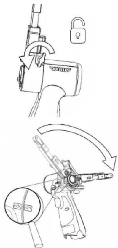
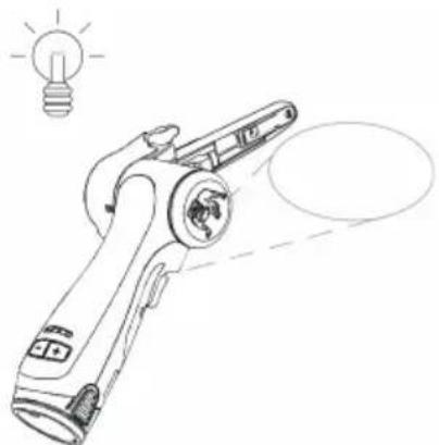
FBS-B 13 tension arm assembly on tool:
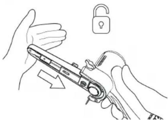
Make sure that the clamping hole is concentrically and perpendicularly aligned against the tool metal sleeve and that the wing nut is opened.
The two arrows on the tool body and tension arm heat cover should be pointing towards each other.
Gently push the arm all the way against the plastic housing and ensure that the plastic tilt angle limiter slots into the tension arm, then position the arm at desired angle and tension the wing nut.
The arm can be fixed at any desired angle within the adjustment range (-90° to 90°).
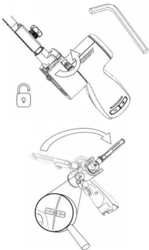
Make sure that the clamping hole is concentrically and perpendicularly aligned against the tool metal sleeve and that the 3mm hex nut is opened.
Verify that the smalltensioning part is correctly aligned to prevent damaging the tensioning surface of the tool during assembly.
Gently push the arm all the way against the plastic housing and ensure that the plastic tilt angle limiter slots into the tension arm, then position the arm at desired angle and tension the hex nut.
The arm can be fixed at any desired angle within the adjustment range (-90° to 90°).
- Install the fully charged battery pack into the sander until it locks in place with a click.
Operating instructions
• The tool is intended to be operated as a hand held tool. The tool can be used in any position.
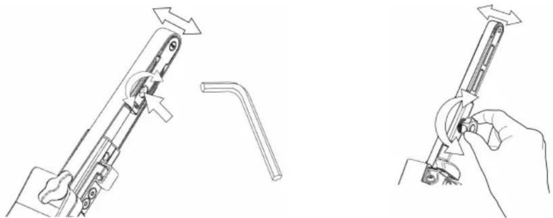
- Select a suitable abrasive belt and secure it to the tool. Make sure the abrasive is centered on the nose pulley wheel and adjust alignment on FBS-B 10 using the small hex nut, on FBS-B 13 using the plastic knob on the side of the tension arm.
natural_image
Technical line drawing showing two mechanical assembly steps: one with a lever mechanism and the other with a hand holding a tool (no text or symbols present)• The sander can now be activated / turned on and started by pressing the switch trigger.
- The sander will run and stay in active mode as long as the trigger is pressed. After the trigger is released the sander will stop but continue to stay in active mode for a short time before it automatically deactivates / turns off.
- When sander is in active mode the right LED is green.
• In active mode the left LED shows the battery status:
Green: Battery charge level is OK.
Flashing green/red: Battery charge level is weak.
Red: Battery voltage too low. Sander is not operable.
- The tool has two speed control modes. In the default mode the speed can be adjusted linearly by changing the position of the trigger. In the other mode the speed remains fixed at the set max rpm when the tool is running. When the rpm+ and rpm− buttons are pressed simultaneously while the tool is in active mode, the tool toggles between the two controlling modes.
- In active mode the max rpm can be adjusted by pressing the rpm+ or rpm- buttons on the tool handle. The rpm can be adjusted in steps of 2,200, 4,000, 6,000, 9,000, 12,000, 15,000 and 17,000 rpm.
• The rpm can be locked to prevent an accidental rpm change. In order to lock rpm:
- Wait until the sander is not in active mode.
- Simultaneously press and hold both rpm+ and rpm- buttons and then pull the switch trigger.
- Repeat this process to unlock the rpm.
If rpm+ or rpm- is pressed when the rpm is locked the right led flashes red twice and the rpm will not change.
- When sanding, always place the tool close to the work surface before starting the tool. Always remove the tool from the work surface before stopping it. This will prevent gouging of the work surface due to excess speed of the abrasive.
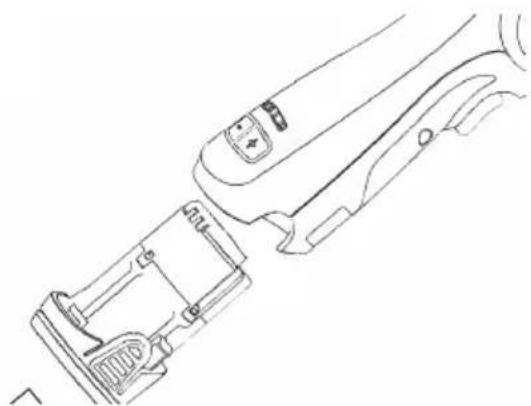
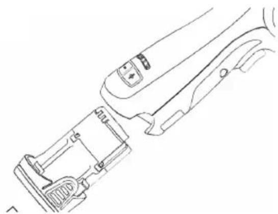
- When sanding is finished, remove the battery from the sander by simultaneously pressing the buttons on both sides and removing the battery from the tool. Charge the battery.
Worklight

Caution: Do not stare directly into worklight!
natural_image
Line drawing of a handheld device with a light bulb above it, no text or symbols presentThis tool is equipped with a worklight which is fixed in position at a 30^ forward angle.
Push the switch trigger to activate the worklight.
The light will automatically turn off 60 seconds after the switch trigger is released.
Bluetooth
This tool is equipped with Bluetooth ^® low energy technology and can be connected to MyMirka app through which additional tool functionality can be accessed. For more information on the app functionality and if it is available in your country, go to www.mirka.com/mymirka
Activate Bluetooth on your Mirka® FBS-B 10 & 13 as follows:
- Connect the battery to the tool.
- Press and hold the rpm+ button while activating the tool by pressing the switch trigger.
- Middle LED is flashing green, to indicate that Bluetooth is active and ready for connections.
- Middle LED is lit green when the tool is connected to another Bluetooth device.
- Bluetooth is deactivated when the tool is deactivated/turned off.
NOTE! If the app is not installed or if it is not available in your country, Bluetooth shall not be activated.
The Bluetooth ^® word mark and logos are registered trademarks owned by the Bluetooth SIG, Inc. and any use of such marks by Mirka Ltd is under license. Other trademarks and trade names are those of their respective owners.
Maintenance

Always remove the battery before maintenance! Only use original Mirka spare parts!
Replacing the belt FBS-B 10
natural_image
Technical line drawing of a mechanical device with internal components (no text or symbols)Remove the battery.

natural_image
Illustration of hands using a tool to adjust a lock, with an open padlock symbol nearby (no text or labels)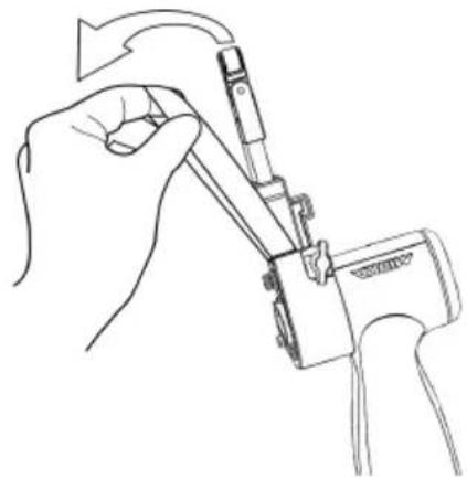
natural_image
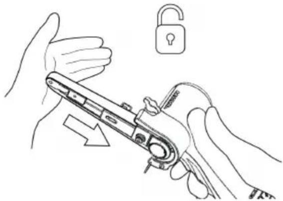
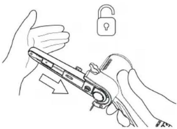
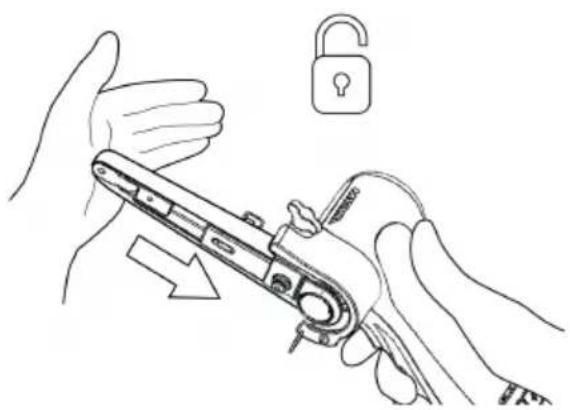
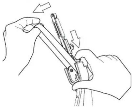
Line drawing of a hand using a tool to adjust or install a component, no text or symbols presentPush the tension arm towards the steel protect cover to release the lock function.
Change the belt, make sure that the belt is centered.
Press the lock function on the tension arm towards the steel cover to engage tension.
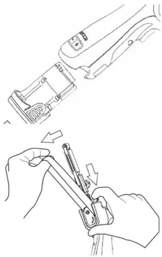
Replacing the belt FBS-B 13
natural_image
Line drawing of a mechanical device with internal components and a handle (no text or symbols)
natural_image
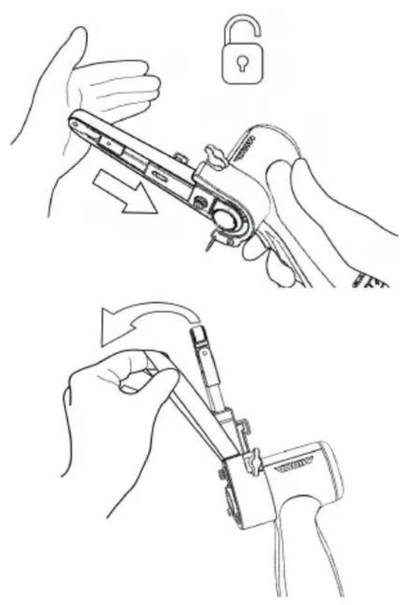
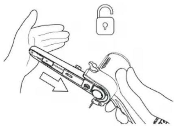
Line drawing of hands using a tool to adjust or install a mechanical component, with arrows indicating direction (no text or symbols)Remove the battery.
Push the plate to loosen the belt tension.
Keep the plate compressed in order to change the belt, make sure that the belt is centered.
Release the push plate to engage tension.
Cleaning
Use a soft brush to remove any accumulated dust. Wear safety glasses to protect your eyes while cleaning. If the body of the tool needs cleaning, wipe it with a soft damp cloth. A mild detergent can be used.

WARNING: Never use alcohol, petrol or other cleaning agent. Never use caustic agents to clean plastic parts.
Charger cleaning instructions
Dirt and grease may be removed from the exterior of the charger using a cloth or soft non metallic brush. Do not use water or any cleaning solutions.

Further service
Servicing must always be performed by trained personnel. To keep the tool warranty valid and ensure optimal tool safety and function, servicing must be carried out by a Mirka authorized service centre. To locate your local Mirka authorized service centre, contact Mirka Customer Service, your Mirka dealer or go to www.mirka.com
Troubleshooting guide
| SolutionPossible causeSymptom | ||
| Nolightfromsander rightLED when trigger is pressed. | Battery pack not properly attached to the sander.Battery totally empty. | Insert the battery properly.Charge the battery. |
| ThesanderLED (right)is red and the sanderslowsdown tothe minimum speed setting when sanding. | Temperature too high in the sander.Too heavy long term load. | Reduce the load on the sander for some time and the sander will speed up again. |
| The sander LED (right) is red and rpm is slightly reduced. | Too heavy short term load. | Use lighter load and the LED (right) will automatically change to green. |
| The left LED is red and the sander is not running. | The battery voltage is too low. | Charge the battery. |
| The leftled ofthe toolis flashingred although the battery is fully charged. | Battery failure. Please use the App for diagnostics. | Replace the battery. |
| The left led of the tool is green, indicating normal battery level, and battery isproperly attachedbutthe tool does not start. | Tool failure. | Contact Mirka service center. |
Disposal information
DANGER
natural_image
Symbol of a trash bin with crossed lines indicating no waste or discharge, and a solid black rectangle below (no text or labels)Render redundant power tools unusable by removing the power cord.
Observe applicable country-specific regulations regarding disposal and recycling of disused machines, packaging and accessories.
EU only: Do not dispose electric power tools in house-hold waste. According to European Directives on waste electrical and electronic equipment and its implementation under national law, electric tools that have reached the end of their life must be collected separately and taken to an environmentally compatible recycling facility.
For more information regarding REACH, RoHS and our corporate social responsibility visit www.mirka.com
| LED | ||||||
| 3 | ||||||
| 2 | ||||||
| 1 | ||||||
| Status | Pre-charge (Trickle charge) | Charging... | Charging... | Charging finished | Over temperature | Battery failure |

Remain continuously on

Flashing
natural_image
Technical line drawing of a mechanical device with a lock and lever mechanism (no text or symbols)natural_image
Technical line drawing of a mechanical device with an inset magnified view showing internal components (no text or symbols)natural_image
Technical line drawing of a mechanical lever assembly with no visible text or symbols
natural_image
Line drawing of a hand using a tool to adjust or install a mechanical component (no text or symbols present)natural_image
Line drawing of a handheld device with a light bulb icon above it, no text or symbols presentnatural_image
Line drawing of a device's internal components, showing a handle, lock, and grip (no text or symbols)Quite la batería.
natural_image
Line drawing of hands holding a mechanical device with an open padlock icon nearby (no text or symbols)natural_image
Line drawing of a hand holding a mechanical device with arrows indicating rotation (no text or symbols)natural_image
Line drawings showing hands using a tool to adjust or install a component, with no visible text or symbols.Quite la batería.
natural_image
Symbol of a trash bin with crossed lines and a solid rectangle below (no text or labels)natural_image
Technical line drawing showing two mechanical assembly steps: one with a lever mechanism and the other with a hand holding a tool (no text or symbols present)natural_image
Line drawing of a handheld device with a light bulb above it, no text or symbols presentnatural_image
Technical line drawing of a mechanical device with internal components (no text or symbols)Eemaldage aku.
natural_image
Illustration of hands using a tool to adjust a lock, with an open padlock symbol nearby (no text or labels)
natural_image
Line drawing of a hand using a tool to adjust or install a component, no text or symbols presentnatural_image
Line drawing of a mechanical device with internal components and a handle (no text or symbols)
natural_image
Line drawing of hands using a tool to adjust or install a mechanical component, with arrows indicating direction (no text or symbols)Eemaldage aku.
natural_image
Symbol of a trash bin with crossed lines indicating no waste or discharge (no text or labels)| LED | ||||||
| 3 | ||||||
| 2 | ||||||
| 1 | ||||||
| Status | Pre-charge (Trickle charge) | Charging... | Charging... | Charging finished | Over temperature | Battery failure |

Remain continuously on

Flashing
Latausdiagnostiikka
natural_image
Line drawing of a hand holding a padlock with an open lock icon (no text or symbols)natural_image
Technical line drawing of a mechanical tool with an arrow indicating rotational motion (no text or symbols present)natural_image
Technical line drawing of a firearm with magnified inset showing internal components (no text or symbols)natural_image
Line drawing of a handheld device with a light bulb above it, no text or symbols presentnatural_image
Line drawing of a mechanical device with internal components and adjustment knobs (no text or symbols)Irrota akku.
natural_image
Illustration of hands using a tool to adjust a device with an open lock icon (no text or symbols present)natural_image
Line drawing of a hand using a tool to adjust or install a device (no text or symbols present)natural_image
Line drawing of a mechanical device with internal components and adjustment knobs (no text or symbols)Irrota akku.
natural_image
Line drawing of hands using a tool to adjust or install a mechanical component (no text or symbols present)natural_image
Symbol of a trash bin with crossed lines indicating no waste or restriction, and a solid black rectangle below (no text or labels)| LED | ||||||
| 3 | ||||||
| 2 | ||||||
| 1 | ||||||
| Status | Pre-charge (Trickle charge) | Charging... | Charging... | Charging finished | Over temperature | Battery failure |

Remain continuously on

Flashing
Diagnostic chargeur
natural_image
Technical line drawing of a mechanical device with a lock and lever mechanism (no text or symbols)
natural_image
Technical line drawing of a mechanical device with a magnified inset showing internal components (no text or symbols)natural_image
Technical line drawing of a mechanical lever assembly with no visible text or symbols
natural_image
Line drawing of a hand using a tool to adjust or install a mechanical component (no text or symbols present)natural_image
Line drawing of a handheld electric shaver with a light bulb icon above it (no text or symbols)natural_image
Technical line drawing of a mechanical device with internal components (no text or symbols)natural_image
Line drawing of hands holding a mechanical device with an open padlock icon nearby (no text or symbols)natural_image
Line drawing of a hand holding a mechanical device with arrows indicating rotation (no text or symbols)natural_image
Line drawing of a mechanical device with internal components and adjustment knobs (no text or symbols)natural_image
Line drawing of hands using a tool to adjust or install a mechanical component, with arrows indicating motion (no text or symbols)natural_image
Symbol of a trash bin with crossed lines indicating no waste, and a solid black rectangle below (no text or labels)Sklop zatezne ručice FBS-B 13 na alatu:
Uvjerite se da je otvor za stezanje koncentrično i okomito poravnat s metalnom čahurom alata i da je krilasta matica otvorena.
- Napunjenu bateriju umetnite u brusilicu tako da se zabravi uz škljocaj.
Uvjerite se da je otvor za stezanje koncentrično i okomito poravnat s metalnom čahurom alata i da je šesterokutna matica od 3 mm otvorena.
natural_image
Technical line drawing showing two mechanical assembly steps: one with a lever mechanism and arrow indicating direction, the other with a hand holding a tool (no text or symbols present)- Brusilicu sada možete aktivirati/uključiti i pokrenuti pritiskom prekidača za pokretanje.
- Brusilica je u pogonu i ostaje u aktivnom načinu rada sve dok je prekidač pritisnut. Nakon otpuštanja prekidača brusilica se zaustavlja, no prije automatskog deaktiviranja/isklijučivanja kratko ostaje u aktivnom načinu rada.
natural_image
Line drawing of a handheld device with a light bulb above it, no text or symbols presentnatural_image
Line drawing of a mechanical device with internal components and control buttons (no text or symbols)Uklonite bateriju.
natural_image
Illustration showing two-step manual techniques for adjusting a mechanical device, with no text or symbols present.natural_image
Line drawings showing two hands using a tool to adjust or install a mechanical component, with arrows indicating the process (no text or symbols present)Uklonite bateriju.
natural_image
Symbol of a trash bin with crossed lines indicating no waste or discharge, and a solid black rectangle below (no text or labels)natural_image
Technical line drawings of mechanical components including a lock, magnifying glass, and tool holder (no text or symbols)natural_image
Pure mechanical component lines without any text, numbers, or symbolsnatural_image
Technical line drawing showing two mechanical assembly steps: one with a lever mechanism and the other with a hand holding a tool (no text or symbols present)natural_image
Line drawing of a handheld device with a light bulb above it, no text or symbols presentnatural_image
Technical line drawing of a mechanical device with internal components (no text or symbols)natural_image
Illustration showing two-step manual techniques for adjusting a mechanical device, with no text or symbols present.natural_image
Line drawings showing two hands using a tool to adjust or install a mechanical component, with arrows indicating the process (no text or symbols present)natural_image
Symbol of a trash bin with crossed lines indicating no waste or discharge (no text or labels)| LED | ||||||
| 3 | ||||||
| 2 | ||||||
| 1 | ||||||
| Status | Pre-charge (Trickle charge) | Charging... | Charging... | Charging finished | Over temperature | Battery failure |

Remain continuously on

Flashing
natural_image
Technical line drawing of a mechanical device with a lock and lever mechanism (no text or symbols)natural_image
Technical line drawing of a mechanical device with an inset magnified view showing internal components (no text or symbols)natural_image
Technical line drawing of a mechanical assembly with no visible text or symbols
natural_image
Line drawing of a hand using a tool to adjust or install a mechanical component (no text or symbols present)natural_image
Line drawing of a handheld device with a light bulb above it, no text or symbols presentnatural_image
Line drawing of a device's internal components, showing a handle, lock, and grip (no text or symbols)natural_image
Line drawing of hands holding a mechanical device with an open padlock icon nearby (no text or symbols)natural_image
Line drawing of a hand holding a mechanical device with arrows indicating rotation (no text or symbols)natural_image
Line drawings showing hands using a tool to adjust or install a mechanical component, with no visible text or symbols.natural_image
Symbol of a trash bin crossed with a diagonal line and a horizontal bar below (no text or labels)Stefan Sjöberg, CEO www.mirka.com
가
: Mirka . mirka.com
EU
UK
RoHS
RCM
natural_image
Line drawing of a hand using a tool to adjust or install a component (no text or symbols present)natural_image
Line drawing of a robotic arm and hand assembly (no text or symbols)배머리를 분리합니다.

Remain continuously on

Flashing
Kroviklio diagnostika
Ikroviklis praneš, jei:
natural_image
Technical line drawing showing two mechanical assembly steps: one with a lever mechanism and arrow indicator, the other with a hand holding a tool (no text or symbols)• Dabar šlifuoklj galima suaktyvinti / ijungti paspaudžiant jungiklj.
natural_image
Line drawing of a handheld device with a light bulb above it, no text or symbols presentnatural_image
Technical line drawing of a mechanical device with internal components (no text or symbols)natural_image
Line drawings showing two hands using a tool to adjust or install a mechanical component, with arrows indicating the process (no text or symbols present)natural_image
Symbol of a trash bin with crossed lines indicating no waste or discharge, and a solid black rectangle below (no text or labels)natural_image
Technical line drawing of a mechanical device with a lock and lever mechanism (no text or symbols)natural_image
Technical line drawing of a mechanical device with a magnified inset showing internal components (no text or symbols)natural_image
Technical line drawing of a mechanical assembly with no visible text or symbols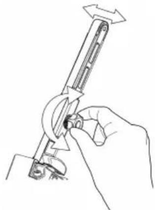
natural_image
Line drawing of a hand using a tool to adjust or install a mechanical component (no text or symbols present)natural_image
Line drawing of a handheld device with a light bulb above it, no text or symbols presentnatural_image
Line drawings showing three different manual techniques for assembling a mechanical component, including grip, lock, and cable (no text or symbols present)Iznemiet akumulatoru.
natural_image
Line drawing of a mechanical device with internal components and a handle (no text or symbols)Iznemiet akumulatoru.

natural_image
Line drawing of hands using a tool to adjust or install a mechanical component, with arrows indicating motion (no text or symbols)natural_image
Symbol of a trash bin with crossed lines indicating no waste or discharge, and a solid black rectangle below (no text or labels)| LED | ||||||
| 3 | ||||||
| 2 | ||||||
| 1 |  | |||||
| Status |  Pre-charge (Trickle charge) Pre-charge (Trickle charge) | Charging... | Charging... | Charging finished | Over temperature | Battery failure |
natural_image
Line drawing of a hand holding a padlock with an open lock icon (no text or symbols)natural_image
Technical line drawing of a mechanical tool with an arrow indicating rotational motion (no text or symbols present)natural_image
Technical line drawing of a firearm with magnified inset showing internal components (no text or symbols)natural_image
Technical line drawing showing two mechanical assembly steps: one with a lever mechanism and the other with a hand holding a tool (no text or symbols present)natural_image
Line drawing of a handheld device with a light bulb above it, no text or symbols presentnatural_image
Technical line drawing of a mechanical device with internal components (no text or symbols)Вадењенабатеријата.
natural_image
Line drawing of hands using a tool to adjust a lock, with an open padlock symbol nearby (no text or labels)
natural_image
Line drawing of a hand using a tool to adjust or install a component, no text or symbols presentnatural_image
Line drawing of a mechanical device with internal components and a handle (no text or symbols)
natural_image
Line drawing of hands using a tool to adjust or install a mechanical component, with arrows indicating motion (no text or symbols)Вадењенабатеријата.
natural_image
Symbol of a trash bin with crossed lines indicating no waste or discharge (no text or labels)| LED | ||||||
| 3 | ||||||
| 2 | ||||||
| 1 | ||||||
| Status | Pre-charge (Trickle charge) | Charging... | Charging... | Charging finished | Over temperature | Battery failure |

Remain continuously on

Flashing
Laderdiagnostiek
natural_image
Technical line drawing of a mechanical device with a lock and lever mechanism (no text or symbols)natural_image
Technical line drawing of a mechanical device with a magnified inset showing internal components (no text or symbols)natural_image
Technical line drawing of a mechanical assembly with no visible text or symbols
natural_image
Line drawing of a hand using a tool to adjust or install a mechanical component (no text or symbols present)Groen: Accuniveau is OK.
Knippert groen/rood: Accuniveau is laag.
natural_image
Line drawing of a handheld device with a light bulb above it, no text or symbols presentnatural_image
Line drawing of a device's internal components, showing a handle, lock, and grip (no text or symbols)natural_image
Line drawing of hands holding a mechanical device with an open padlock icon nearby (no text or symbols)natural_image
Line drawing of a hand holding a mechanical device with a tool, no text or symbols presentnatural_image
Line drawing of a mechanical device with internal components and adjustment knobs (no text or symbols)natural_image
Line drawing of hands using a tool to adjust or install a mechanical component, with arrows indicating motion (no text or symbols)natural_image
Symbol of a trash bin with crossed lines and a solid rectangle below (no text or labels)| LED | ||||||
| 3 | ||||||
| 2 | ||||||
| 1 |  | |||||
| Status |  (Ti (Ti   ) ) | Charging... | Charging... | Charging finished | Over temperature | Battery failure |
Laderdiagnostikk
Laderen indikerer hvis:
- Før den fulladede batteripakken inn i slipemaskinen til den låses på plass med et klikk.
natural_image
Technical line drawing showing two mechanical assembly steps: one with a lever mechanism and the other with a hand holding a tool (no text or symbols present)natural_image
Line drawing of a handheld device with a light bulb above it, no text or symbols presentnatural_image
Technical line drawing of a mechanical device with internal components (no text or symbols)Fjern batteriet.

natural_image
Illustration showing two-step manual techniques for adjusting a mechanical device, with no text or symbols present.natural_image
Line drawings showing two hands using a tool to adjust or install a mechanical component, with arrows indicating the process (no text or symbols present)Fjern batteriet.
natural_image
Symbol of a trash bin with crossed lines indicating no waste or discharge, and a solid black rectangle below (no text or labels)| LED | ||||||
| 3 | ||||||
| 2 | ||||||
| 1 | ||||||
| Status | Pre-charge (Trickle charge) | Charging... | Charging... | Charging finished | Over temperature | Battery failure |

Remain continuously on

Flashing
natural_image
Technical line drawing of a mechanical device with a lock and lever mechanism (no text or symbols)natural_image
Technical line drawing of a mechanical device with a magnified inset showing internal components (no text or symbols)natural_image
Technical line drawing of a mechanical lever assembly with no visible text or symbols
natural_image
Line drawing of a hand using a tool to adjust or install a mechanical component (no text or symbols present)natural_image
Line drawing of a handheld device with a light bulb above it, no text or symbols presentnatural_image
Line drawing of a mechanical device with internal components and adjustment knobs (no text or symbols)Usuńakumulator.

natural_image
Line drawing of hands using a tool to adjust or install a mechanical component, with arrows indicating motion (no text or symbols)natural_image
Symbol of a trash bin crossed with no text or labels, accompanied by a solid black rectangle below (no text or symbols present)| LED | ||||||
| 3 | ||||||
| 2 | ||||||
| 1 | ||||||
| Status | Pre-charge(Trickle charge) | Charging... | Charging... | Charging finished | Over temperature | Battery failure |
natural_image
Technical line drawing of a mechanical device with a lock and lever mechanism (no text or symbols)natural_image
Diagram of a firearm with magnified inset showing internal components (no text or labels)natural_image
Technical line drawing of a mechanical assembly with no visible text or symbols
natural_image
Line drawing of a hand using a tool to adjust or install a mechanical component (no text or symbols present)natural_image
Line drawing of a handheld device with a light bulb above it, no text or symbols presentnatural_image
Line drawing of a mechanical device with internal components and a handle (no text or symbols)Remover a bateria.

natural_image
Line drawing of hands using a tool to adjust or install a mechanical component, with arrows indicating motion (no text or symbols)natural_image
Symbol of a trash bin with crossed lines and a solid rectangle below (no text or labels)Declaratie de conformitate
Mirka Ltd, 66850 Jeppo, Finlanda
Stefan Sjöberg, Director
ExecutivCompania
Producător/Furnizor
Mirka Ltd
66850 Jeppo, Finlanda
Tel.+358 20 760 2111
Fax +358 20 760 2290
www.mirka.com

natural_image
Line drawing of a padlock with an open lock icon (no text or symbols)natural_image
Technical line drawing of a mechanical device with an arrow indicating rotation or assembly (no text or symbols present)natural_image
Diagram of a firearm with magnified inset showing internal components (no text or labels)natural_image
Technical line drawing of a mechanical assembly with directional arrows and a separate L-shaped component (no text or symbols)
natural_image
Line drawing of a hand using a tool to adjust or install a mechanical component (no text or symbols present)natural_image
Line drawing of a handheld device with a light bulb above it, no text or symbols presentnatural_image
Line drawings showing hands using a tool to adjust or install a mechanical component, with no visible text or symbols.Scoateți bateria.
natural_image
Symbol of a trash bin with crossed lines indicating no waste or restriction, and a solid black rectangle below (no text or labels)| LED | ||||||
| 3 | ||||||
| 2 | ||||||
| 1 | ||||||
| Status | Pre-charge(Trickle charge) | Charging... | Charging... | Charging finished | Over temperature | Battery failure |

Remain continuously on

Flashing
natural_image
Technical line drawing of a mechanical device with a lock and handle, no text or symbols presentnatural_image
Diagram of a firearm with magnified inset showing internal components (no text or labels)natural_image
Technical line drawing of a mechanical assembly with no visible text or symbols
natural_image
Line drawing of a hand holding a tool with a circular component, no text or symbols presentnatural_image
Line drawing of a handheld device with a light bulb above it, no text or symbols presentnatural_image
Line drawing of a mechanical device with internal components and adjustment knobs (no text or symbols)Извлечьаккумулятор.
natural_image
Line drawing of hands holding a mechanical device with an open lock icon (no text or symbols)natural_image
Line drawing of a hand using a tool to adjust or install a mechanical component (no text or symbols present)natural_image
Line drawings showing hands using a tool to adjust or install a component, with no visible text or symbols.Извлечьаккумулятор.
natural_image
Symbol of a trash bin with crossed lines indicating no waste or restriction, and a solid black rectangle below (no text or labels)Diagnostika polnilnika
natural_image
Technical line drawing showing two mechanical assembly steps: one with a lever mechanism and arrow indicating direction, the other with a hand holding a tool (no text or symbols present)natural_image
Line drawing of a handheld device with a light bulb above it, no text or symbols presentnatural_image
Line drawing of a mechanical device with internal components and adjustment knobs (no text or symbols)Odstranite baterijo.

natural_image
Illustration showing two-step manual techniques for adjusting a mechanical device, with no text or symbols present.natural_image
Line drawings showing two hands using a tool to adjust or install a mechanical component, with arrows indicating the process (no text or symbols present)Odstranite baterijo.
Potisnite ploščo, da sprostite napetost traku.
natural_image
Symbol of a trash bin with crossed lines indicating no waste or discharge, and a solid black rectangle below (no text or labels)Kako početi?
- Prilikom otpakivanja alatke proverite da li je čitava, kompletna i da nije oštećena tokom transporta. Nikada nemojte da koristite oštećenu alatku.
- Uverite se da je zatezna ručica pravilno pričvršćena za alatku i da su plastični poklopac za zaštitu od toplote, gumeni štitnik i drugi delovi pravilno montirani na zateznu ručicu.
Sklop zatezne ručice FBS-B 10 na alatki:

Sklop zatezne ručice FBS-B 13 na alatki:
Uverite se da je otvor za stezanje koncentrično i okomito poravnat u odnosu na metalnu čauru alata i da je leptir-navrtka otvorena.
Uverite se da je otvor za stezanje koncentrično i okomito poravnat u odnosu na metalnu čauru alata i da je šestougaona navrtka od 3 mm otvorena.
Proverite da li je mali deo za zatezanje pravilno poravnat kako biste sprečili oštećenje zatezne površine alatke tokom montaže.
Lagano gurnite ručicu do kraja na plastično kućište i uverite se da plastični graničnik ugla nagiba ulazi u zateznu ručicu, zatim postavite ručicu pod željenim uglom i zategnite šestougaonu navrtku.
natural_image
Technical line drawing showing two mechanical assembly steps: one with a lever mechanism and arrow indicating direction, the other with a hand holding a tool (no text or symbols present)natural_image
Line drawing of a handheld device with a light bulb above it, no text or symbols presentOva alatka je opremljena radnim svetlom koje je učvršćeno pod uglom od 30° prema napred.
Pritisnite okidni prekidač da biste aktivirali radno svetlo.
Svetlo će se automatski isključiti 60 sekundi nakon otpuštanja okidnog prekidača.
Bluetooth
Ovaj alat je opremljen tehnologijom Bluetooth ^® male energetske potrošnje i može da se poveže sa aplikacijom MyMirka, putem koje je moguć pristup dodatnim funkcijama alata. Više informacija o funkcijama aplikacije i o tome da li je ona dostupna u vašoj zemlji potražite na www.mirka.com/mymirka
natural_image
Technical line drawing of a mechanical device with internal components (no text or symbols)Uklonite bateriju.

Pritisnite zateznu ručku prema čeličnom zaštitnom poklopcu da biste odblokirali funkciju zaključavanja.
Zamenite traku, pazeći da je traka centrirana.
Pritisnite funkciju zaključavanja na zateznu ručku prema čeličnom poklopcu da biste aktivirali zatezanje.
Zamena trake FBS-B 13
Uklonite bateriju.
Gurnite ploču da bi se smanjila napetost kaiša.
Držite stisnutu ploču da biste promenili traku, proverite da li je traka centrirana.
Pustite potisnu ploču da biste aktivirali zatezanje.
Čišćenje
Koristite meku četku da biste uklonili akumuliranu prašinu. Nosite zaštitne naočare da biste zaštitili oči dok obavljate čišćenje.
Ako je potrebno čišćenje tela alata, obrišite ga mekom vlažnom krpom. Možete koristiti blagi deterdžent.

natural_image
Symbol of a trash bin with crossed lines indicating no waste or discharge (no text or labels)Laddardiagnostik
natural_image
Technical line drawing showing two mechanical assembly steps: one with a lever mechanism and the other with a hand holding a tool (no text or symbols present)natural_image
Line drawing of a handheld device with a light bulb above it, no text or symbols presentnatural_image
Technical line drawing of a mechanical device with internal components (no text or symbols)Ta ut batteriet.

natural_image
Illustration showing two-step manual techniques for adjusting a mechanical device, with no text or symbols present.natural_image
Line drawings showing two hands using a tool to adjust or install a mechanical component, with arrows indicating the process (no text or symbols present)Ta ut batteriet.
natural_image
Symbol of a trash bin with crossed lines indicating no waste or discharge, and a solid black rectangle below (no text or labels)Şarj tanılama
natural_image
Technical line drawing showing two mechanical assembly steps: one with a lever mechanism and arrow indicating direction, the other with a hand holding a tool (no text or symbols present)natural_image
Line drawing of a handheld device with a light bulb above it, no text or symbols presentnatural_image
Technical line drawing of a mechanical device with internal components (no text or symbols)Pili çıkarın.

natural_image
Illustration of hands using a tool to adjust a lock, with an open padlock symbol nearby (no text or labels)
natural_image
Line drawing of a hand using a tool to adjust or install a component, no text or symbols presentnatural_image
Line drawing of a mechanical device with internal components and a handle (no text or symbols)
natural_image
Line drawing of hands using a tool to adjust or install a mechanical component (no text or symbols present)Pili çıkarın.
natural_image
Symbol of a trash bin with crossed lines indicating no waste or discharge, and a solid black rectangle below (no text or labels)Declaration of conformity
Mirka Ltd, 66850 Jeppo, Finland
declare under our sole responsibility that the Mirka® products (listed below and see "Technical data" table for particular model) to which this declaration relates are in conformity with the following standards or other normative documents: EN 62841-1:2015+AC:2015+A11:2022, EN 62841-2-4:2014+AC:2015, EN 55014-1:2021, EN 55014-2:2021, EN 300 328 V2.2.2, EN 301 489-1 V2.2.3, EN 301 489-17 V3.2.4 & EN IEC 63000:2018 in accordance with the regulations 2006/42/EC, 2014/53/EU, 2011/65/EU, 2015/863/EU & 2012/19/EU. The battery charger are in conformity with the following standards and directives; EN 60335-1:2012/A15:2021, EN 60335-2-29:2021/A1:2021, EN 62233:2008, EN 55014-1:2017, EN 55014-2:2015, EN 61000-3-2:2014, EN 61000-3-3:2013 & EN IEC 63000:2018 in accordance with the regulations 2014/35/EU, 2014/30/EU, 2011/65/EU, 2015/863/EU & 2012/19/EU.
Products: Mirka® FBS-B 10 & 13
Jeppo 02/01/2024
Place and date of issue


Manufacturer/Supplier
Mirka Ltd
66850 Jeppo, Finland
Tel.+358 20 760 2111
Fax +358 20 760 2290
www.mirka.comStefan Sjöberg, CEOCompany

Original instructions. We reserve the right to make changes to this manual without prior notice.
Important
Read these safety and operating instructions carefully before installing, operating or maintaining this tool. Keep these instructions in a safe and accessible place. Read and comply with state and local regulations.
Note: Mirka products are in continuous development. Please visit mirka.com for the latest version of these instructions.
Required personal safety equipment

Read operator's manual

Wear safety glasses

Wear
ear protection

Wear safety gloves

Wear face mask
Symbols
 | Complies with EU relevant standards |
| Complies with UK relevant regulations |
 | Complies with China RoHS requirement |
 | Complies with Australia & New Zealand RCM requirement |
 | Complies with Eurasian conformity requirements |
| Complies with Brazilian conformity requirements |

Warning: Potential hazardous situation that may result in death or serious injury and/or property damage.
Caution: Potential hazardous situation that may result in minor or moderate injury and/or property damage.

Intertek
4000415
Mirka® FBS-B 10 & 13 Cordless Beltsander
CONFORMS TO UL STD 62841-1, 62841-2-4.
CERTIFIED TO CSA STD C22.2 No. 62841-1, C22.2 No. 62841-2-4.
Mirka® BCA 108 Battery Charger
CONFORMS TO UL STD 1310.
CERTIFIED TO CSA STD C22.2 No. 223.
Please read and comply with
- General Industry Safety & Health Regulations, part 1910, OSHA 2206, available from: Superintendent of Documents; Government Printing Office; Washington DC 20402
• State and local regulations

General Power Tool Safety Warnings

WARNING Read all safety warnings and all instructions. Failure to follow the warnings and instructions may result in electric shock, fire and/or serious injury.
Save all warnings and instructions for future reference. The term "power tool" in the warnings refers to your mains-operated (corded) power tool or battery-operated (cordless) power tool.
1. Work area safety
a. Keep work area clean and well lit. Cluttered or dark areas invite accidents.
b. Do not operate power tools in explosive atmospheres, such as in the presence of flammable liquids, gases or dust. Power tools create sparks which may ignite the dust or fumes.
c. Keep children and bystanders away while operating a power tool. Distractions can cause you to lose control.
2. Electrical safety
a. Power tool plugs must match the outlet. Never modify the plug in any way. Do not use any adapter plugs with earthed (grounded) power tools. Unmodified plugs and matching outlets will reduce risk of electric shock.
b. Avoid body contact with earthed or grounded surfaces, such as pipes, radiators, ranges and refrigerators. There is an increased risk of electric shock if your body is earthed or grounded.
c. Do not expose power tools to rain or wet conditions. Water entering a power tool will increase the risk of electric shock.
d. Do not abuse the cord. Never use the cord for carrying, pulling or unplugging the power tool. Keep cord away from heat, oil, sharp edges and moving parts. Damaged or entangled cords increase the risk of electric shock.
e. When operating a power tool outdoors, use an extension cord suitable for outdoor use. Use of a cord suitable for outdoor use reduces the risk of electric shock.
f. If operating a power tool in a damp location is unavoidable, use a residual current device (RCD) protected supply. Use of an RCD reduces the risk of electric shock.
3. Personal safety
a. Stay alert, watch what you are doing and use common sense when operating a power tool. Do not use a power tool while you are tired or under the influence of drugs, alcohol or medication. A moment of inattention while operating power tools may result in serious personal injury.
b. Use personal protective equipment. Always wear eye protection. Protective equipment such as a dust mask, non-skid safety shoes, hard hat, or hearing protection used for appropriate conditions will reduce personal injuries.
c. Prevent unintentional starting. Ensure the switch is in the off-position before connecting to power source and/or battery pack, picking up or carrying the tool. Carrying power tools with your finger on the switch or plugging in tools when the switch is in the on-position invites accidents.
d. Remove any adjusting key or wrench before turning the power tool on. A wrench or a key left attached to a rotating part of the power tool may result in personal injury.
e. Do not overreach. Keep proper footing and balance at all times. This enables better control of the power tool in unexpected situations.
f. Dress properly. Do not wear loose clothing or jewellery. Keep your hair, clothing and gloves away from moving parts. Loose clothes, jewellery or long hair can be caught in moving parts.
g. If devices are provided for the connection of dust extraction and collection facilities, ensure these are connected and properly used. Use of dust collection can reduce dust-related hazards.
h. Do not let familiarity gained from frequent use of tools allow you to become complacent and ignore tool safety principles. A careless action can cause severe injury within a fraction of a second.
4. Power tool use and care
a. Do not overload the power tool. Use the correct power tool for your application. The correct power tool will do the job better and safer at the rate for which it was designed.
b. Do not use the power tool if the switch does not turn it on and off. Any power tool that cannot be controlled with the switch is dangerous and must be repaired.
c. Disconnect the plug from the power source and/or the battery pack from the power tool before making any adjustments, changing accessories, or storing power tools. Such preventive safety measures reduce the risk of starting the power tool accidentally.
d. Store idle power tools out of the reach of children and do not allow persons unfamiliar with the power tool or these instructions to operate the power tool. Power tools are dangerous in the hands of untrained users.
e. Maintain power tools and accessories. Check for misalignment or binding of moving parts, breakage of parts and any other condition that may affect the power tool's operation. If damaged, have the power tool repaired before use. Many accidents are caused by poorly maintained power tools.
f. Keep cutting tools sharp and clean. Properly maintained cutting tools with sharp cutting edges are less likely to bind and are easier to control.
g. Use the power tool, accessories and tool bits etc. in accordance with these instructions, taking into account the working conditions and the work to be performed. Use of the power tool for operations different from those intended could result in a hazardous situation.
h. Keep handles and grasping surfaces dry, clean and free from oil and grease. Slippery handles and grasping surfaces do not allow for safe handling and control of the tool in unexpected situations.
5. Battery tool use and care
a. Recharge only with the charger specified by the manufacturer. A charger that is suitable for one type of battery pack may create a risk of fire when used with another battery pack.
b. Use power tools only with specifically designated battery packs. Use of any other battery packs may create a risk of injury and fire.
c. When battery pack is not in use, keep it away from other metal objects, like paper clips, coins, keys, nails, screws or other small metal objects, that can make a connection from one terminal to another. Shorting the battery terminals together may cause burns or a fire.
d. Under abusive conditions, liquid may be ejected from the battery; avoid contact. If contact accidentally occurs, flush with water. If liquid contacts eyes, additionally seek medical help. Liquid ejected from the battery may cause irritation or burns.
e. Do not use a batter pack or tool that is damaged or modified. Damaged or modified batteries may exhibit unpredictable behaviour resulting in fire, explosion or risk of injury.
f. Do not expose a battery pack or tool to fire or excessive temperature. Exposure to fire or temperature above 130 °C may cause explosion.
g. Follow all charging instructions and do not charge the battery pack or tool outside the temperature range specified in the instructions. Charging improperly or at temperatures outside the specified range may damage the battery and increase the risk of fire.
6. Service
a. Have your power tool serviced by a qualified repair person using only identical replacement parts. This will ensure that the safety of the power tool is maintained.
b. Never service damaged battery packs. Service of battery packs should only be performed by the manufacturer or authorized service providers

Safety rules for battery pack and charger
- Important safety and operating instructions for your battery and charger. Before using the charger, read all instructions and warnings on the charger, the battery pack and the tool.
- If the battery pack casing is cracked or damaged, do not insert into charger. There is a danger of electric shock or electrocution.
- Do not allow any liquid to get inside charger. Electric shock may result.
- This charger is not intended for any uses other than charging rechargeable batteries.
- Do not place any object on top of the charger, near any heat source or place the charger on a soft surface that may result in excessive internal heat.
- Make sure the cord is located so it will not be stepped on, tripped over, or otherwise subjected to damage or stress.
- Do not use the charger if it has received a sharp blow, been dropped or otherwise damaged in any way.
- Do not store or use the tool and battery pack in locations where the temperature may reach or exceed 50^ (122°F).
- The charger is designed to operate on standard household electrical power (100–240 VAC). Do not attempt to use it on any other voltage.
• Children should be supervised to ensure that they do not play with the appliance

Additional Safety Warnings
• Always ensure that the work piece to be sanded is firmly fixed in place.
• Always remove battery during any transportation of the tool.
- Do not allow the tool to free speed without taking precautions to protect surrounding people and objects in the event that the abrasive or other moving parts should come loose.
- Read all instructions before using this tool. All operators must be fully trained in the proper, safe use of this tool.
- All maintenance must be carried out by trained personnel. For service, contact a Mirka authorized service center.
- If the tool appears to malfunction, stop using it immediately and arrange for service and repair.
- Before changing the abrasive always disconnect the power source
- Never carry, store or leave the tool unattended with the power source connected.
- Keep hands clear of the spinning pad during use.
- Always wear required personal safety protection in accordance with manufacturer's instructions and local/national standards while using this tool.
- Read the Materials Safety Data Sheet (MSDS) for the working surface.
- If any physical hand/wrist discomfort is experienced, stop working and seek medical attention. Hand, wrist and arm injury may result from repetitive work, motion and overexposure to vibrations.
Additional information on battery and charger
- Never attempt to open the battery pack for any reason. If the plastic housing of the battery pack breaks or cracks, immediately discontinue use and do not recharge.

Additional Warnings
Some dust created by power sanding, sawing, grinding, drilling, and other construction activities contains chemicals known to cause cancer, birth defects or other reproductive harm. Some examples of these chemicals are:
- lead from lead-based paints,
• crystalline silica from bricks and cement and other masonry products, and
• arsenic and chromium from chemicallytreated lumber.
Your risk from these exposures varies, depending on how often you do this type of work. To reduce your exposure to these chemicals: work in a well ventilated area, and work with approved safety equipment, such as those dust masks that are specially designed to filter out microscopic particles.
Technical data
| " | FBS-B 13FBS-B 10Mirka | |
| 12 VDC12 VDCVoltage | ||
| Speed° | 2200 –18000 rpm | 2200 –18000 rpmFBS-B 13FBS-B 10Mirka |
| Weight (tool only) | 0.70 kg (1.5 lbs) | 0.74 kg (1.6 lbs) |
| Belt size | 10 x 330 mm(3/8" x 13" ") | 13 x 457 mm(1/2" x 18" ") |
| Belt speed | 2.6 – 20.5 m/s | 2.5 – 19.6 m/s |
| Mirka BCA 108Battery charger | |
| 120 VAC, 60 HzInput | |
| Charging time | < 50 min (2.5 Ah)< 100 min (5.0 Ah) |
| Storage temperature range | -20 °C – 80 °C (-4 °F – 176 °F) |
| Charging temperature | 4 °C – 40 °C (39 °F – 104 °F) |
| Dimension | 191 x 102 x 86 mm(7 1/2" x 4" x 3 3/8") |
| 0.66 kg (1.5 lbs)Weight | |
| II /Degree of protection |
| Battery pack | Mirka BPA 10825 | Mirka BPA 10850 | Mirka BPA 11125 | Mirka BPA 11150 |
| Type | RechargeableLi-ion | RechargeableLi-ion | RechargeableLi-ion | RechargeableLi-ion |
| Battery voltage | 10.8 VDC | 10.8 VDC | 11.1 VDC | 11.1 VDC |
| Capacity | 2.5 Ah / 27.0 Wh | 5.0 Ah / 54.0 Wh | 2.5 Ah / 27.75 Wh | 5.0 Ah / 55.5 Wh |
| Weight | 0.18 kg (0.4 lbs) | 0.38 kg (0.8 lbs) | 0.18 kg (0.4 lbs) | 0.38 kg (0.8 lbs) |
| Intelligent battery | Yes | Yes | Yes | Yes |
Noise and vibration information
The measured values may be used for comparing one tool with another and in a preliminary assessment of exposure.
| Cordless | FBS-B 10 | FBS-B 13 |
| Sound pressure level (LpA) | 72.0 dB(A) | 72.0 dB(A) |
| Sound power level (LWA) | 80.0 dB(A) | 80.0 dB(A) |
| Sound measurement uncertainty KWA | 3.0 dB(A) | 3.0 dB(A) |
| Vibration emission value ah* | 3.125 m/s2 | 3.125 m/s2 |
| Vibration emission uncertainty KPA* | 1.5 m/s2 | 1.5 m/s2 |
Specifications subject to change without prior notice. Model range may vary between markets.
* The values stated in the table are derived from laboratory testing in conformity with stated codes and standards and are not sufficient for risk evaluation. Values measured in a particular work place may be higher than the declared values. The actual exposure values and amount of risk or harm experienced by an individual are unique to each situation and depend upon the surrounding environment, the way the individual operates the machinery, the particular material being worked, work station design and the user's exposure time and physical condition. Mirka accepts no responsibility for the consequences of using declared values instead of actual exposure values for any individual risk assessment.
Further occupational health and safety information can be obtained from the following websites:
https://osha.europa.eu/en (Europe) or http://www.osha.gov (USA)
Proper use of tool
This sander is designed for sanding all types of materials such as paints, metals, wood, composites, plastics, etc., using abrasives specially designed for this purpose. Do not use this sander for any other purpose than that specified without consulting the manufacturer or the manufacturer's authorized supplier. Any maintenance or repair work requiring the motor housing to be opened may only be carried out by an authorized service center.
Battery and charger
- The battery pack is not fully charged out of the carton. First read the safety instructions and then charge your battery according to the instructions.
- For optimal charging capacity the battery should be charged at an ambient temperature between 18 °C (64 °F) and 24 °C (75 °F). To prevent damage to the battery pack, do not charge the battery pack where the air temperature is below 4 °C (39°F) or above 40 °C (104 °F).
• To obtain the longest possible battery life, we suggest the following: - Store and charge your battery in a cool area. Temperatures above or below normal room temperature will shorten battery life.
– Never store the battery in a discharged condition. Recharge it immediately after it has been discharged. - All batteries gradually lose their charge. The higher the temperature, the quicker they lose their charge.
If you store your tool for long periods of time without use, recharge the battery every month. This practice will prolong battery life.
Charging procedure
- Connect the power cord to the charger, and then plug into an outlet before inserting battery pack. All three charging lights will be on for two seconds and then turn off.
- Insert the battery pack into the charger. The lights will start to flash within 30 seconds.
- During the charging process, the charging lights will indicate the status as follows:
- Three charging lights will flash in sequence during the charging process.
– Fully charged, all three lights will remain on continuously. - The charging process will last approximately 50 minutes for BPA 10825/11125 and 100 minutes for BPA 10850/11150 battery pack.
NOTE! This charger can only charge Mirka 12V battery packs.
NOTE! Charging times may be longer depending on the surrounding temperature and battery conditions.
LED indication of BCA 108 charger
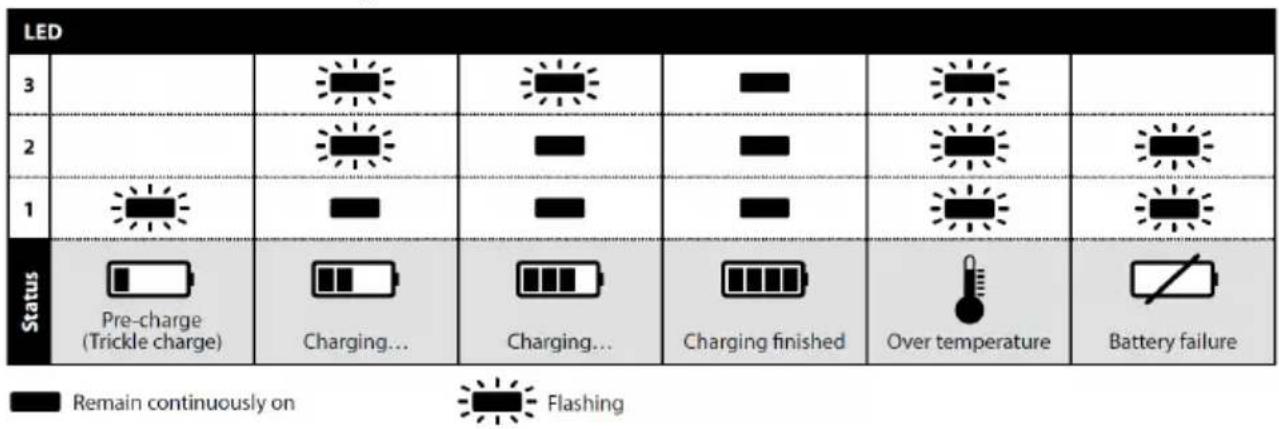
Charger diagnostics
The charger will indicate if:
- A battery pack is overheated. All three charging lights will flash. Remove the battery and allow it to cool down for 15–30 minutes and re-insert.
- A malfunction occurs in the battery or the charger. Two charging lights will flash. Remove the battery and allow it to cool down. Re-insert the battery pack into the charger. If two charging lights still flash, the battery or charger may require service.
How to get started
-
When unpacking the tool, make sure it is intact, complete and has not been damaged in transport. Never use a damaged tool.
-
Make sure the tension arm is properly attached to the tool and that the protective plastic heat cover, rubber guard and other parts are correctly mounted onto the tension arm.
FBS-B 10 tension arm assembly on tool:
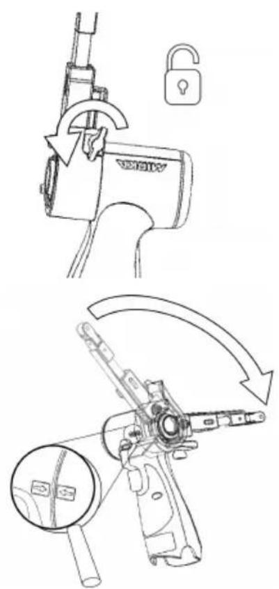
Make sure that the clamping hole is concentrically and perpendicularly aligned against the tool metal sleeve and that the wing nut is opened.
The two arrows on the tool body and tension arm heat cover should be pointing towards each other.
Gently push the arm all the way against the plastic housing and ensure that the plastic tilt angle limiter slots into the tension arm, then position the arm at desired angle and tension the wing nut.
The arm can be fixed at any desired angle within the adjustment range (-90° to 90°).
FBS-B 13 tension arm assembly on tool:
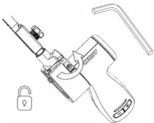
Make sure that the clamping hole is concentrically and perpendicularly aligned against the tool metal sleeve and that the 3mm hex nut is opened.
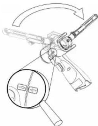
natural_image
Technical line drawing of a firearm with magnified inset showing internal components (no text or symbols)Verify that the small tensioning part is correctly aligned to prevent damaging the tensioning surface of the tool during assembly.
Gently push the arm all the way against the plastic housing and ensure that the plastic tilt angle limiter slots into the tension arm, then position the arm at desired angle and tension the hex nut.
The arm can be fixed at any desired angle within the adjustment range (-90° to 90°).
- Install the fully charged battery pack into the sander until it locks in place with a click.
Operating instructions
• The tool is intended to be operated as a hand held tool. The tool can be used in any position.
- Select a suitable abrasive belt and secure it to the tool. Make sure the abrasive is centered on the nose pulley wheel and adjust alignment on FBS-B 10 using the small hex nut, on FBS-B 13 using the plastic knob on the side of the tension arm.
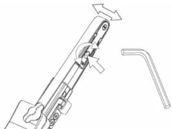
natural_image
Technical line drawing of a mechanical component with directional arrows indicating movement (no text or symbols)
natural_image
Line drawing of a hand using a tool to adjust or install a mechanical component (no text or symbols present)- The sander can now be activated / turned on and started by pressing the switch trigger.
- The sander will run and stay in active mode as long as the trigger is pressed. After the trigger is released the sander will stop but continue to stay in active mode for a short time before it automatically deactivates / turns off.
- When sander is in active mode the right LED is green.
• In active mode the left LED shows the battery status:
Green: Battery charge level is OK.
Flashing green/red: Battery charge level is weak.
Red: Battery voltage too low. Sander is not operable.
- The tool has two speed control modes. In the default mode the speed can be adjusted linearly by changing the position of the trigger. In the other mode the speed remains fixed at the set max rpm when the tool is running. When the rpm+ and rpm- buttons are pressed simultaneously while the tool is in active mode, the tool toggles between the two controlling modes.
- In active mode the max rpm can be adjusted by pressing the rpm+ or rpm- buttons on the tool handle. The rpm can be adjusted in steps of 2 200, 4 000, 6 000, 9 000, 12 000, 15 000 and 17 000 rpm.
- The rpm can be locked to prevent an accidental rpm change. In order to lock rpm:
- Wait until the sander is not in active mode.
- Simultaneously press and hold both rpm+ and rpm- buttons and then pull the switch trigger.
- Repeat this process to unlock the rpm.
If rpm+ or rpm- is pressed when the rpm is locked the right led flashes red twice and the rpm will not change.
- When sanding, always place the tool close to the work surface before starting the tool. Always remove the tool from the work surface before stopping it. This will prevent gouging of the work surface due to excess speed of the abrasive.
- When sanding is finished, remove the battery from the sander by simultaneously pressing the buttons on both sides and removing the battery from the tool. Charge the battery.
Worklight

Caution: Do not stare directly into worklight!

natural_image
Line drawing of a handheld device with a light bulb above it, no text or symbols presentThis tool is equipped with a worklight which is fixed in position at a 30^ forward angle.
Push the switch trigger to activate the worklight.
The light will automatically turn off 60 seconds after the switch trigger is released.
Bluetooth
This tool is equipped with Bluetooth ^® low energy technology and can be connected to MyMirka app through which additional tool functionality can be accessed. For more information on the app functionality and if it is available in your country, go to www.mirka.com/mymirka
Activate Bluetooth on your Mirka® FBS-B 10 & 13 as follows:
- Connect the battery to the tool.
- Press and hold the rpm+ button while activating the tool by pressing the switch trigger.
- Middle LED is flashing green, to indicate that Bluetooth is active and ready for connections.
- Middle LED is lit green when the tool is connected to another Bluetooth device.
- Bluetooth is deactivated when the tool is deactivated/turned off.
NOTE! If the app is not installed or if it is not available in your country, Bluetooth shall not be activated.
The Bluetooth ^® word mark and logos are registered trademarks owned by the Bluetooth SIG, Inc. and any use of such marks by Mirka Ltd is under license. Other trademarks and trade names are those of their respective owners.
FCC Rules & Industry Canada's licence-exempt RSS
Compliance with the radio regulations in North America has been verified in accordance with FCC Part 15 subpart B and C, RSS-GEN, RSS-247 and FCC §15.247. Operation is subject to the following two conditions:
- This device may not cause harmful interference.
- This device must accept any interference received, including interference that may cause undesired operation.
NOTE! This equipment has been tested and found to comply with the limits for a Class B digital device, pursuant to part 15 of the FCC Rules. These limits are designed to provide reasonable protection against harmful interference in a residential installation. This equipment generates, uses and can radiate radio frequency energy and, if not installed and used in accordance with the instructions, may cause harmful interference to radio communications.
However, there is no guarantee that interference will not occur in a particular installation. If this equipment does cause harmful interference to radio or television reception, which can be determined by turning the equipment off and on, the user is encouraged to try to correct the interference by one or more of the following measures:
- Reorient or relocate the receiving antenna.
- Increase the separation between the equipment and receiver.
- Connect the equipment into an outlet on a circuit different from that to which the receiver is connected.
- Consult the dealer or an experienced radio/TV technician for help.
CAUTION TO THE USER: Changes or modification not expressly approved by the party responsible for compliance could void the user's authority to operate the equipment.
Maintenance

Always remove the battery before maintenance!
Only use original Mirka spare parts!
Replacing the belt FBS-B 10
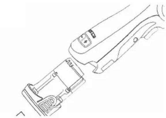
natural_image
Line drawing of a mechanical device with internal components and adjustment knobs (no text or symbols)
natural_image
Line drawing of hands holding a mechanical device with an open padlock icon nearby (no text or symbols)
natural_image
Line drawing of a hand holding a mechanical device with arrows indicating rotation (no text or symbols)Remove the battery.
Push the tension arm towards the steel protect cover to release the lock function.
Change the belt, make sure that the belt is centered.
Press the lock function on the tension arm towards the steel cover to engage tension.
Replacing the belt FBS-B 13
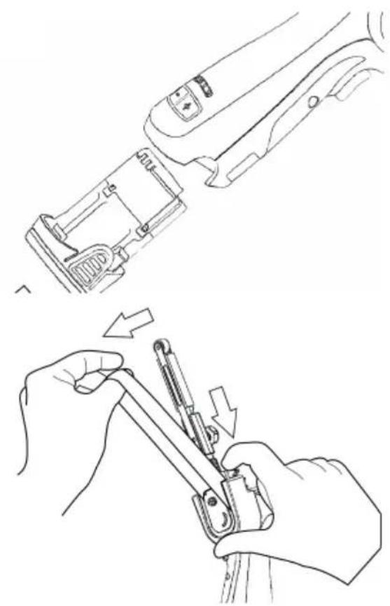
natural_image
Line drawings showing hands using a tool to adjust or install a mechanical component (no text or symbols present)Remove the battery.
Push the plate to loosen the belt tension.
Keep the plate compressed in order to change the belt, make sure that the belt is centered.
Release the push plate to engage tension.
Cleaning
Use a soft brush to remove any accumulated dust. Wear safety glasses to protect your eyes while cleaning. If the body of the tool needs cleaning, wipe it with a soft damp cloth. A mild detergent can be used.

WARNING: Never use alcohol, petrol or other cleaning agent. Never use caustic agents to clean plastic parts.
Charger cleaning instructions
Dirt and grease may be removed from the exterior of the charger using a cloth or soft non metallic brush. Do not use water or any cleaning solutions.

Further service
Servicing must always be performed by trained personnel. To keep the tool warranty valid and ensure optimal tool safety and function, servicing must be carried out by a Mirka authorized service centre. To locate your local Mirka authorized service centre, contact Mirka Customer Service, your Mirka dealer or go to www.mirka.com
Troubleshooting guide
| SolutionPossible causeSymptom | ||
| NolightfromsanderrightLEDwhen trigger is pressed. | Battery pack not properly attached to the sander.Battery totally empty. | Insert the battery properly.Charge the battery. |
| Thesander LED (right) isredandthe sanderslows down to the minimum speed setting when sanding. | Temperature too high in the sander.Too heavy long term load. | Reduce the load on the sander for some time and the sander will speed up again. |
| The sander LED (right) is red and rpm is slightly reduced. | Too heavy short term load. | Use lighter load and the LED (right) will automatically change to green. |
| The left LED is red and the sander is not running. | The battery voltage is too low. | Charge the battery. |
| The left led ofthetoolisflashing red although the battery is fully charged. | Battery failure. Please use the App for diagnostics. | Replace the battery. |
| The left led of the tool is green, indicating normal battery level, and battery is properly attached but the tool does not start. | Tool failure. | Contact Mirka service center. |
Disposal information
DANGER
natural_image
Symbol of a trash bin with crossed lines indicating no waste or restriction, and a solid black rectangle below (no text or labels)Render redundant power tools unusable by removing the power cord.
Observe applicable country-specific regulations regarding disposal and recycling of disused machines, packaging and accessories.
EU only: Do not dispose electric power tools in house-hold waste. According to European Directives on waste electrical and electronic equipment and its implementation under national law, electric tools that have reached the end of their life must be collected separately and taken to an environmentally compatible recycling facility.
For more information regarding REACH, RoHS and our corporate social responsibility visit www.mirka.com
Mirka® FBS-B 10 & 13 Cordless Beltsander
CONFORMS TO UL STD 62841-1, 62841-2-4.
CERTIFIED TO CSA STD C22.2 No. 62841-1, C22.2 No. 62841-2-4.
Mirka® BCA 108 Battery Charger
CONFORMS TO UL STD 1310.
CERTIFIED TO CSA STD C22.2 No. 223.
- General Industry Safety & Health Regulations, part 1910, OSHA 2206, available from: Superintendent of Documents; Government Printing Office; Washington DC 20402
Additional Safety Warnings
natural_image
Line drawing of a hand holding a padlock with an open lock icon (no text or symbols)natural_image
Technical line drawing of a mechanical tool with an arrow indicating rotational motion (no text or symbols present)natural_image
Technical line drawing of a firearm with magnified inset showing internal components (no text or symbols)natural_image
Technical line drawing showing two mechanical assembly steps: one with a lever mechanism and the other with a hand holding a tool (no text or symbols present)natural_image
Line drawing of a handheld device with a light bulb above it, no text or symbols presentFCC Rules & Industry Canada's licence-exempt RSS
natural_image
Line drawing of a device's internal components, showing a handle, lock, and grip (no text or symbols)
natural_image
Line drawing of hands holding a mechanical device with an open padlock nearby (no text or symbols)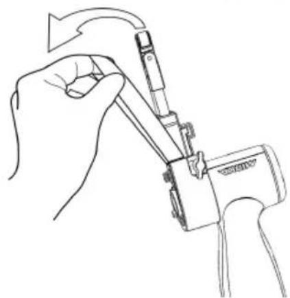
natural_image
Line drawing of a hand holding a mechanical device with arrows indicating rotation (no text or symbols)Retire la batería.
natural_image
Line drawing of a mechanical device with internal components and adjustment knobs (no text or symbols)Retire la batería.

natural_image
Line drawing of hands using a tool to adjust or install a mechanical component, with arrows indicating motion (no text or symbols)natural_image
Symbol of a trash bin crossed with two crossed lines and a solid black rectangle below (no text or labels)Mirka® FBS-B 10 & 13 Cordless Beltsander
CONFORMS TO UL STD 62841-1, 62841-2-4.
CERTIFIED TO CSA STD C22.2 No. 62841-1, C22.2 No. 62841-2-4.
Mirka® BCA 108 Battery Charger
CONFORMS TO UL STD 1310.
CERTIFIED TO CSA STD C22.2 No. 223.
- General Industry Safety & Health Regulations, part 1910, OSHA 2206, available from: Superintendent of Documents; Government Printing Office; Washington DC 20402
Diagnostic chargeur
natural_image
Line drawing of a hand holding a padlock with an open lock icon (no text or symbols)natural_image
Technical line drawing of a mechanical tool with an arrow indicating rotational motion (no text or symbols present)natural_image
Technical line drawing of a firearm with magnified inset showing internal components (no text or symbols)natural_image
Technical line drawing showing two mechanical assembly steps: one with a lever mechanism and the other with a hand holding a tool (no text or symbols present)natural_image
Line drawing of a handheld device with a light bulb above it, no text or symbols presentFCC Rules & Industry Canada's licence-exempt RSS
natural_image
Line drawing of a mechanical device with internal components and adjustment knobs (no text or symbols)Retirer la pile.

natural_image
Line drawing of hands using a tool to adjust or install a mechanical component, with arrows indicating motion (no text or symbols)natural_image
Symbol of a trash bin with crossed lines indicating no waste or restriction, and a solid black rectangle below (no text or labels)符合性声明
Mirka Ltd, 66850 Jeppo, Finland
natural_image
Technical line drawing of a mechanical device with a magnified inset showing internal components (no text or symbols)FBS-B13 张力臂在工具上的安装:
natural_image
Technical line drawing of a mechanical clamp or lever assembly with a lock icon (no text or symbols)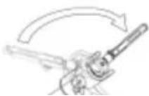
natural_image
Technical line drawing of a mechanical assembly with no visible text or symbols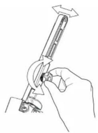
natural_image
Line drawing of a hand holding a mechanical tool with directional arrows indicating motion (no text or symbols)natural_image
Line drawing of a handheld device with a light bulb above it, no text or symbols presentnatural_image
Line drawing of a handheld device with buttons and a scroll (no text or symbols)取下电地。
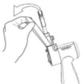
natural_image
Line drawing of a hand holding a tool with a pen, no text or symbols present更换砂带,确保砂带层中。
natural_image
Line drawing of a hand holding a tool, showing a mechanical device with a brush and a separate view (no text or symbols)取下电池。
推动推板,减少砂带张力。
natural_image
Technical line drawing of a mechanical device with a lock and lever mechanism (no text or symbols)natural_image
Diagram of a firearm with magnified inset showing internal components (no text or labels)natural_image
Technical line drawing of a mechanical assembly with no visible text or symbols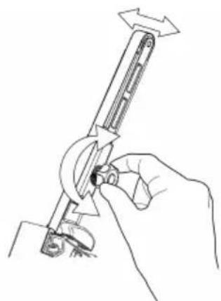
natural_image
Line drawing of a hand using a tool to adjust or install a mechanical component (no text or symbols present)natural_image
Line drawing of a handheld device with a light bulb above it, no text or symbols presentnatural_image
Line drawings showing hands using a tool to adjust or install a component, with no visible text or symbols.Remova a bateria.
natural_image
Symbol of a trash bin crossed with no text or labels, accompanied by a black rectangular block below (no readable text or symbols)Declaration of conformity
| Mirka Ltd, 66850 Jeppo, Finlanddeclare under our sole responsibility that the Mirka® products (listed below and see "Technical data" table for particular model) to which this declaration relates are in conformity with the following standards or other normative documents: BS EN 62841-1:2015+AC:2015+A11:2022, BS EN 62841-2-4:2014+AC:2015, BS EN 55014-1:2021, BS EN 55014-2:2021, EN 300 328 V2.2.2, EN 301 489-1 V2.1.1, EN 301 489-17 V3.1.1 & BS EN IEC 63000:2018 in accordance with regulations Supply of Machinery (Safety) Regulations 2008, The Restriction of the Use of Certain Hazardous Substances in Electrical and Electronic Equipment Regulations 2012, Radio Equipment Regulations 2017. The battery charger is in conformity with the following standards and directives; BS EN 60335-1:2012/A15:2021, BS EN 60335-2-29:2021/A1:2021, BS EN 62233:2008, BS EN 55014-1:2017, BS EN 55014-2:2015, BS EN 61000-3-2:2014, BS EN 61000-3-3:2013 & BS EN IEC 63000:2018 in accordance with the regulations Electrical Equipment (Safety) Regulations 2016, Electromagnetic Compatibility Regulations 2016, The Restriction of the Use of Certain Hazardous Substances in Electrical and Electronic Equipment Regulations 2012. | ||
| Products: Mirka® FBS-B 10 & 13 | ||
| Jeppo 01.02.2024Place and date of issue |  Company Company |  Stefan Sjöberg, CEO Stefan Sjöberg, CEO |
| Manufacturer / SupplierMirka Ltd66850 Jeppo, FinlandTel. +358 20 760 2111Fax +358 20 760 2290www.mirka.com | Importer InformationMirka (UK) LtdSaxon HouseShirwell CrescentFurzton LakeMilton KeynesMK4 1GATel. +44 (0)1908 866100 |  |
This chapter is an addition to the English language chapter of the manual in order to fulfill the UKCA regulation requirements. Please refer to the English language chapter for more information about your product.
Statement of Compliance
We Mirka Ltd, hereby declare under our sole responsibility that the above-mentioned products, to which this statement relates, complies with the compliance conditions in Schedule 2 of The Product Security and Telecommunications Infrastructure (Security Requirements for Relevant Connectable Products) Regulations 2023.
The defined support period for the above-mentioned products is two years after the production date. The production date can be found on the marking plate of the products month/year.
geo
| Location | Value | | -------- | ----- | | Mirka Ltd | 100 | | Finland | 50 |MirkaLtd
Finland
BrazilMirkaBrasilLtda.
BelgiumMirkaBelgiumLogisticsNV
CanadaMirkaCanadalnc.
ChinaMirkaTradingShanghaiCo.,Ltd
Finland&BalticsMirkaLtd
FranceMirkaFranceSarl
GermanyMirkaGmbH
IndiaMirkalndiaPvtLtd
ItalyMirkaltalias.r.l., CafroS.p.A.
MexicoMirkaMexicanaS.A.deC.V.
NetherlandsMirkaBeneluxB.V
PolandMirkaPolandSp.zo.o
SingaporeMirkaAsiaPacificPteLtd
SpainKWHMirkalbéricaS.A.U.
SwedenMirkaScandinaviaAB
TurkeyMirkaTurkeyZimparaLtdŞirketi
UnitedKingdomMirka(UK)Ltd
UnitedArabEmiratesMirkaMiddleEastFZCO
USAMirkaUSAInc.
Forcontactinformation,
pleasevisitwww.mirka.com