
YT-99763 - Heating Yato - Free user manual and instructions
Find the device manual for free YT-99763 Yato in PDF.

| Product type | Infrared liquid fuel heater (diesel / kerosene) |
| Brand and model | Yato YT-99763 |
| Dimensions (L x W x H) | 1305 x 431 x 1115 mm |
| Weight (without fuel) | 56.2 kg |
| Power supply | 220-240 V~, 50 Hz |
| Motor power | 60 W |
| Thermal power | 18 kW |
| Fuel consumption | 1.42 kg/h |
| Tank capacity | 60 liters |
| Autonomy on full tank | ~36 hours |
| Recommended heating area | 110-140 m³ |
| Set temperature range | 0 to 55 °C |
| Pump pressure | 10 bar |
| Main functions | Adjustable thermostat, timer (1-24 h), ECO cyclic mode, panel lock |
| Maintenance and cleaning | Regularly clean the exterior with a soft cloth; blow the interior with compressed air. Drain the tank if storing for >10 days. |
| Safety features | Flame sensor, overheat protection (auto shut-off), thermal switch, fuel level sensor |
| Spare parts and repairability | Fuel injector, ignition electrodes, fuel filter, temperature probe, level sensor, PCB board. Repairs only by an authorized center. |
| Intended use | Well-ventilated industrial and utility premises. Do not use in homes, basements, or cellars. |
| Safety distance | Rear: 1 m, front: 3 m, sides: 0.6 m, top: 1.5 m |
| Insulation class | II |
| Protection rating | IP20 (indoor dry use) |
Frequently Asked Questions - YT-99763 Yato
User questions about YT-99763 Yato
0 question about this device. Answer the ones you know or ask your own.
Ask a new question about this device
Download the instructions for your Heating in PDF format for free! Find your manual YT-99763 - Yato and take your electronic device back in hand. On this page are published all the documents necessary for the use of your device. YT-99763 by Yato.
USER MANUAL YT-99763 Yato
natural_image
Exterior view of a modern industrial machine with visible control panel and wheels (no text or symbols)YT-99760
natural_image
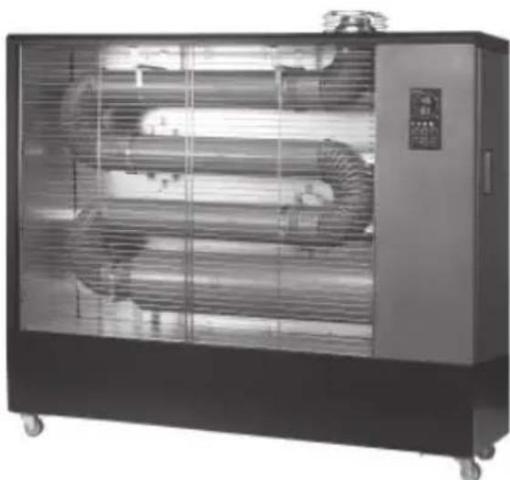
Exterior view of a large industrial rotary oven with cooling fans and control panel (no visible text or symbols)YT-99763
CE
PL EN DE RU UA LT LV CZ SK HU RO ES FR IT NL GR BG PT HR AR
natural_image
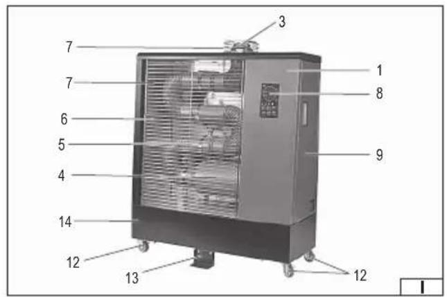
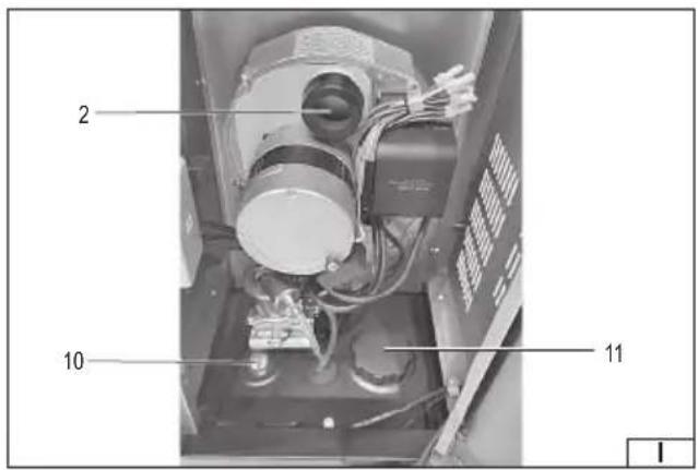
Technical line drawing of a large industrial machine with fan and control panel (no text or symbols)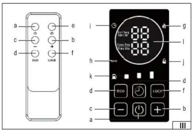
- casing
- air intake
- combustion chamber outlet
- combustion chamber
- radiant pipe
- hot air outlet
- protective cover
- control panel
- side door
- fuel gauge
- fuel filler cap
- transport wheel
- support leg
- base/fuel tank
DE
Read the operating instruction
WARNING! Do not open the side door while the appliance is operating
This symbol indicates that waste electrical and electronic equipment (including batteries and storage cells) cannot be disposed of with other types of waste. Waste equipment should be collected and handed over separately to a collection point for recycling and recovery, in order to reduce the amount of waste and the use of natural resources. Uncontrolled release of hazardous components contained in electrical and electronic equipment may pose a risk to human health and have adverse effects for the environment. The household plays an important role in contributing to reuse and recovery, including recycling of waste equipment. For more information about the appropriate recycling methods, contact your local authority or retailer.
WYPOSAŻENIE PRODUKTU
– model YT-99760: 325 cm²
– model YT-99763: 450 cm ^2
PRODUCT CHARACTERISTICS
The infrared oil heater is designed for heating well-ventilated industrial and utility rooms. Heat is generated by burning liquid fuel in the combustion chamber and transferred to the radiant tube, which emits infrared radiation, directly heating surfaces within the range of operation. The correct, reliable and safe operation of the product depends on proper use, therefore:
Before using the product, read the entire manual and keep it. If you pass on the product to someone else, pass on the manual along with it.
The supplier is not liable for any damage or injury resulting from use of the product for purposes other than its intended use, failure to comply with safety regulations and recommendations in this manual. Use of the product for purposes other than its intended use also results in loss of the user's rights to the guarantee, as well as under the warranty.
PRODUCT EQUIPMENT
The product is delivered complete, but assembly or appropriate adjustment is required as described later in the manual.
SAFETY INSTRUCTIONS
General recommendations for use
The appliance becomes very hot during use. Be especially careful when handling the product, especially near the combustion chamber outlet, hot air outlet and metal covers. Improper use can result in serious burns, fire, carbon monoxide (CO) poisoning and/or explosion. Keep children and animals away from the product while it is in use.
This product may be used by children aged 8 years and over and by persons with reduced physical, mental abilities and persons lacking experience and knowledge of the product if supervision or instruction is provided regarding the safe use of the product so that the hazards involved are understood. Children should not play with the product. Children should not clean or maintain the product without supervision. The product should be stored out of the reach of children.
Before use, carefully read this manual and follow all instructions contained therein. Keep the manual in an easily accessible place for quick reference. It is forbidden to use the product by persons who have not read the manual. Installation, first start-up, adjustment, inspections and all service activities should be carried out only by qualified personnel. Failure to follow the instructions may result in property damage, personal injury, fire or explosion.
Do not leave the product unattended during operation. Do not leave the product connected to the power supply unattended. Do not touch the heated elements of the heater during operation or immediately after use - wait until it cools down completely. Before starting maintenance or moving, disconnect the product from the power supply and make sure it has cooled down completely. Before connecting the product to the mains, make sure that the switch is in the off position. Avoid accidental start-up.
The product must not be exposed to precipitation, water, moisture or conductive dust. Do not use the heater in rain, snow, fog or in places where electrical or mechanical components may become damp. Water entering the product may cause electric shock or permanent damage. The product is intended for indoor and dry use only.
The product must not be used in potentially explosive, corrosive or dusty atmospheres. It must not be used in rooms where there are volatile flammable substances such as gasoline, solvents, paints, adhesives, wood dust, fibers or other flammable materials. The absorption
EN
of such substances by the product may result in fire or explosion. It is prohibited to store or use liquid fuels and fl ammable vapors near the product.
The product should only be used in a vertical position, on a stable, even, hard and non-flammable surface. The floor and ceiling in the place where the heater works should be made of fi reproof materials.
The air inlet, hot air outlet and combustion chamber outlet must be free from obstruction at all times. They must not be blocked, covered or restricted in any way. This may result in overheating, improper operation, fire or damage to the product.
During operation of the heater, continuous and efficient ventilation must be ensured.
Recommendations for connecting the device to the power supply
Before connecting the device to the power supply, make sure that the voltage, frequency and capacity of the power supply correspond to the values shown on the nameplate. The plug must fit the socket. It is forbidden to modify the plug or socket in any way to fit each other.
The appliance must be connected directly to a single mains socket. It is recommended that the circuit is equipped with a residual current device (RCD). The mains circuit must be equipped with a protective conductor and 16 A fuse. When using extension cords, a three-wire extension cord with a 16 A current load must be used.
Avoid contact of the power cable with sharp edges and hot objects and surfaces, including those belonging to the device. When the product is in operation, the power cable must always be fully unwound and its position must be determined so that it does not constitute an obstacle during operation of the product. The positioning of the power cable must not cause a tripping hazard. The power socket should be located in such a place that it is always possible to quickly disconnect the plug of the product's power cable. When disconnecting the power cable plug, always pull on the housing of the plug, never on the cable. The power cable must not be brought near a hot device. If the power cable or plug is damaged, immediately disconnect it from the mains and contact an authorized service center of the manufacturer for replacement. The power cable must not be replaced by yourself. Do not use the product with a damaged power cable or plug. The power cable or plug cannot be repaired, in the event of damage to these elements, they must be replaced with new ones free from defects.
Recommendations for use
The heater is intended for use in well-ventilated non-residential rooms only. The device consumes oxygen from the air - when used in closed rooms, constant ventilation with an area of at least 25cm^2/kW of heating power must be ensured, with the total area of the openings not being less than 250cm^2 . Ventilation openings must be arranged at the top and bottom of the room. The air in the room should be changed regularly, at least twice per hour. For every 100 W of the device's thermal power, 1m^3 of free space is recommended, with the room volume not being less than 100m^3 . The thermal power of the device is given on the rating plate and in the technical data table.
Do not use the heater in residential premises, basements, cellars or places below ground level. The appliance is intended for use only in public or industrial buildings. Lack of adequate ventilation may cause improper combustion, which may result in the formation of carbon
EN
monoxide. Carbon monoxide is an odorless, toxic gas that can lead to serious poisoning or death.
Symptoms of carbon monoxide poisoning may include headaches, dizziness, difficulty breathing, nausea, and weakness. If such symptoms occur, immediately turn off the heater, ventilate the room, and go to fresh air. If necessary, contact a doctor. The product should be checked at an authorized service center of the manufacturer.
The product should not be used in places where flammable materials may be sucked in through the air intake.
Any attempts at independent repairs, dismantling of covers or modification of the structure are prohibited. All service activities may only be performed by qualified personnel. The heater must not be used if any irregularities in its operation are observed.
The air inlet, hot air outlet and combustion chamber outlet must not be restricted or covered in any way. Restricting air flow may result in improper operation of the product, overheating of components or fire. It is prohibited to unscrew the fuel filler cap or refuel while the device is running. This may cause fire or explosion.
Heater Setup Requirements
The heater must be placed on a stable, flat, horizontal, hard and non-flammable surface. The product is designed to operate in a vertical position only. The heater must not be placed in places where it may tip over, on sloping surfaces, in corners or under low ceilings. The heater must not be installed below an electrical socket. The product is a portable device and is not intended to be attached to walls or suspended from the ceiling.
The product may only be used in covered and dry spaces, such as halls, workshops, warehouses or other industrial premises. It is not permitted to use the heater outdoors without a roof or in places exposed to atmospheric precipitation. The product should not be used in residential buildings or in residential rooms, in basements, basements, cellars or other spaces below ground level. The heater is intended for use only in well-ventilated industrial or public utility buildings.
In the case of indoor work, permanent ventilation openings with a total area of at least 25 cm^2 per 1 kW of thermal output must be provided, with the total area of the openings not being less than 250 cm^2 . The ventilation openings should be evenly distributed at the bottom and top of the room.
Minimum required ventilation area:
- Model YT-99760: 325 cm²
- Model YT-99763: 450 cm²
For safety reasons, ensure there is sufficient free space around the product:
– at the back (air intake): minimum 1 m
– front (hot air outlet): minimum 3 m
- on the sides: minimum 0.6 m
– above the product: minimum 1.5 m
- under the product: placed directly on the ground
Make sure that the heater is located away from damp places, flammable objects and other sources of fire or heat. The air inlet and outlet must not be restricted or covered in any way.
EN
Restriction of air flow may lead to overheating, improper operation or fire. The product must only be used in places where the floor and ceiling are made of fireproof materials. It is forbidden to connect the heater to ventilation or supply duct systems.
PRODUCT SERVICE
Preparing for work
Note! All actions described in this section must be performed with the product disconnected from the power supply. Make sure that the power cable plug is disconnected from the power outlet.
The product should be unpacked, completely removing all packaging elements. It is recommended to keep the packaging, it can be helpful in later transport and storage of the product. Inspect the product for damage. If any damage is found, do not use the product until the damage is repaired or the damaged elements are replaced with new, damage-free ones.
Product installation
The heater must be placed on a stable, even, non-flammable and hard surface. The product must be installed in accordance with the requirements described in the section of the instructions „Heater installation requirements”. Before starting, make sure that the product has been properly set up and prepared for operation.
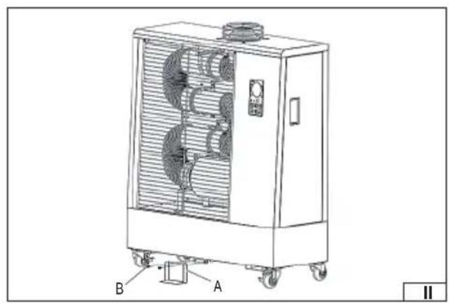
Two support legs must be mounted to the base of the heater: one at the front and one at the rear of the lower base (tank) of the heater. As shown in illustration (II), each support leg (A) must be attached to the base of the device using two mounting screws (B). The screws must be tightened firmly and securely so that the components do not move during use. Properly mounted support legs ensure the stability of the product and prevent it from tipping over.
When using the product indoors, constant ventilation must be ensured through a chimney. If the chimney passes through a wall made of flammable material, fireproof insulation of at least 3 cm thick must be used.
The chimney flue should be made of stainless steel. The length of the flue must not exceed 4 meters, and the number of elbows (bends) must not exceed 2 pieces. Exceeding these parameters - more than two elbows or a chimney flue length exceeding 4 meters - may lead to incomplete combustion and, as a result, to improper operation of the heater. It is forbidden to connect the heater to ventilation or supply duct systems.
Filling the tank with fuel
NOTE! Only the oil specified in the technical data table should be used as fuel. It is forbidden to use any other fuel than that recommended by the manufacturer to power the heater. It is forbidden to use volatile fuels such as: alcohol, petrol, solvents, fuel-oil mixtures. It is forbidden to use contaminated fuel or used engine oil. It is necessary to use fuel free from any contamination. It is recommended to use high-quality products.
Before filling the fuel tank, make sure that the device is disconnected from the power supply and has cooled down completely. It is forbidden to fill the fuel while the heater is working. Do not fill the fuel tank above the full tank mark. You must leave a free space between the fuel surface and the top of the fuel tank.
It is recommended to use a fuel filler and/or funnel to refill the fuel. This will reduce the risk of spilling. If fuel is spilled during refilling, wipe off any remaining fuel before starting the heater. In the event of fuel contact with the skin, wash the affected areas immediately with soap and water and rinse with water.
Smoking is prohibited while refueling.
Fuel should be poured into the tank through the opening under the fuel filler cap.
To do this, open the heater side door. Then turn the fuel filler cap (I) counterclockwise and then remove the cap from the filler. Closing is done by turning the cover clockwise as far as it will go. Only in this way can the filler cap be mounted or dismounted.
The fuel tank capacity is specified in the table. The tank is equipped with a mechanical fuel level indicator (I). If the indicator is near the mark marked with the letter „E“, the tank is empty. If the indicator is near the mark marked with the letter „F“, the tank is full.
Make sure that the fuel filler cap is properly closed. Check that the fuel tank is not damaged and that there is no fuel leakage from the tank. It is forbidden to use the heater with a leaking tank or fuel installation. If you find a damaged fuel tank, contact an authorized service center of the manufacturer for repair.
Control panel and remote control
Below is a description of the items on the remote control and control panel, shown in Illustration (III):
a. Power button – used to turn the heater on and off. After turning on the device, if the ambient temperature is lower than the set value, the heater will automatically start working.
b. „+” button – increases the set heating temperature. The maximum value depends on the model and is visible on the display.
c. "−" button – decreases the set heating temperature.
d. ECO button – activates the cyclic mode, allowing you to set work and pause intervals (e.g. 20 minutes of work / 10 minutes of break). Pressing it several times allows you to select the appropriate value. Holding the button for 3 seconds deactivates the cyclic mode.
EN
Timer button – allows you to set the device to turn off automatically after 1 to 24 hours. When the display is flashing, select the desired value. Holding the button for 3 seconds cancels the set timer.
f. LOCK button – allows you to activate or deactivate the control panel lock. The lock also activates automatically after 1 minute of inactivity. To unlock the panel, hold the button for 3 seconds.
g. Heater/flame operation indicator light – lights up when the burner is actively operating and indicates that the device is currently heating.
h. ECO mode indicator light – lights up when the cycling function is active.
i. Timer indicator light – indicates that the function to automatically turn off the heater after the programmed time has elapsed is enabled.
j. Button lock indicator light (LOCK) – indicates that the control panel is locked.
k. Fuel level indicator – indicates the current fuel level in the tank.
I. Display – allows reading of the set temperature (top row) and ambient temperature (bottom row). In programming modes, it also displays timer or cyclic mode settings.
Starting the heater
Note! Before using the heater, make sure that the device is properly assembled, positioned and installed.
Connect the heater to an electrical outlet.
Caution! Do not leave the device unattended while operating.
After connecting the power supply, the display on the control panel will show the „--” symbol in the upper row and the current ambient temperature in the lower row.
Press the power button.
The default temperature is 20^ C – this value is displayed in the top row of the display.
If the ambient temperature is lower than the set temperature, the device will automatically start the ignition cycle: the electrodes spark and after approximately 7 seconds the heater starts.
If the ambient temperature is higher than the set temperature, use the „+” and „-” buttons to adjust the set temperature value – the device will start operating once the ignition conditions are reached.
Timer function
To activate the delayed switch-off function, press the timer button. The display will flash and the digits will blink five times. During this time, press the timer button until the desired value is reached (from 1 to 24 hours). After confirming the setting, the timer indicator light will come on. To cancel the timer, hold the button for 3 seconds - the indicator light will go out.
ECO mode (cyclic operation)
To turn on the cyclic mode, press the ECO button – the display will flash five times and the possible settings will appear: 10, 20 or 30 minutes. Press the ECO button again while it is flashing to select the appropriate cycle (e.g. 20 means: 20 minutes of work and 10 minutes of break). After confirming the setting, the ECO indicator light will come on. To turn off the cyclic mode, hold the button for 3 seconds – the indicator light will go out.
Control panel lock
If no button is pressed for 1 minute, the panel will automatically enter lock mode, which protects against accidental or unauthorized changes to settings. The lock indicator will light up. In lock mode, only basic functions are active, such as maintaining operation according to the current settings. To unlock the panel, hold down the LOCK button for 3 seconds.
Manually turning off the heater
To manually turn off the heater, press the power button. The display will show the „--” symbol again. In the event of a longer break in operation, disconnect the device from the power supply. Note! Do not disconnect the device from the power supply if the fan is still running after the heater has been turned off. Disconnecting the heater from the power supply while the fan is running will interrupt the cooling process of the device and may result in damage to the heater. Wait until the fan has completely stopped working and only then disconnect the device from the power supply. Wait until the device has completely cooled down. You can start maintenance.
Maintenance, storage and transportation
Warning! Before starting any maintenance operation, make sure that the appliance is completely cooled down and disconnected from the mains socket.
CLEANING, MAINTENANCE, STORAGE AND TRANSPORT
NOTE! Before performing any cleaning or maintenance activities, turn off the device, disconnect it from the power supply and allow it to cool down completely.
Do not attempt to repair the device or electrical components – in the event of faults, contact a qualified service center.
EN
Do not use a damaged device until it has been checked and repaired by a service center.
When cleaning, be careful not to allow water to enter the interior of the device.
Do not open the device casing to clean the inside. Do not direct a water jet at the product.
Do not use solvents, gasoline, toluene or other aggressive chemicals for cleaning.
The product housing should be regularly wiped with a soft sponge or cloth. In case of heavier dirt, use a sponge dampened with lukewarm water and a mild detergent, and then dry with a clean cloth. The air inlet and all ventilation holes should be kept clean - dust and dirt should be regularly removed from their surfaces. To clean the inside of the product, gently blow with a stream of compressed air at a pressure of no more than 0.3 MPa . Regularly check the condition of the power cord - if you notice any abrasions, cracks or other damage, contact an authorized service center of the manufacturer to replace the cord. Do not immerse the device in water or any other liquid and do not clean it with a stream of water or any other liquid. Store the device disconnected from the power supply, the plug of the power cable must be disconnected from the mains socket.
If the heater is to be stored for a period longer than 10 days, the fuel must be removed from the tank. The fuel removal procedure is described in the section of the instructions „Emptying the fuel tank". Before storing the heater, make sure that the product is completely cooled and dry. The storage location should provide good ventilation and protect against direct sunlight, moisture and precipitation, as well as protect against access by unauthorized persons, especially children. Heaters should be transported with an empty fuel tank, in the factory packaging.
Emptying the fuel tank
The fuel tank drain plug is located at the rear bottom of the fuel tank. The heater should be placed with its wheels slightly elevated so that the fuel can drain freely from the entire tank. Place a container under the drain plug that can hold the amount of fuel in the tank. Unscrew the drain plug. After you have finished emptying the fuel tank, tighten the drain plug. Clean the fuel outlet from any fuel residue.
Service
SEASONAL INSPECTION - BY QUALIFIED STAFF ONLY
Do not disassemble the device yourself or attempt to repair it. Repairs to the device may only be performed by an authorized service center of the manufacturer. Any modification of the product not described in the instructions is prohibited. It is not allowed to interfere with the heater's construction yourself. Do not dismantle factory-assembled elements or factory-sealed elements.
Fuel nozzle:
Unscrew the nozzle from the body and clean the passage hole with compressed air. If necessary, replace the nozzle with a new one.
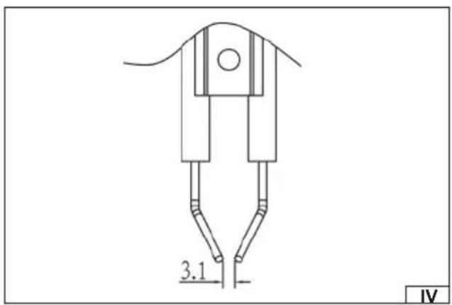
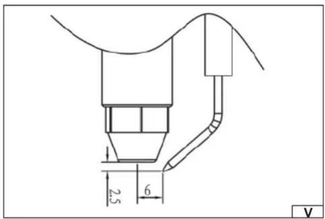
Ignition electrodes:
Clean, adjust and, if necessary, replace the ignition electrodes. The gaps between the electrodes are shown in illustrations (IV) and (V).
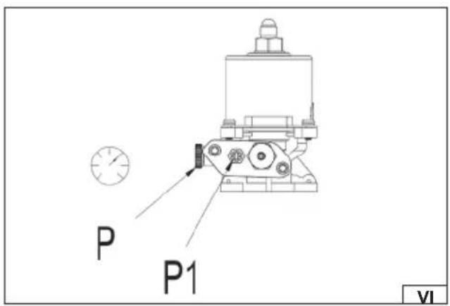
Compressor pressure adjustment (VI):
The fuel pressure is factory set and can only be adjusted by an authorized service center. Doing so yourself can be dangerous.
To check and, if necessary, adjust the pressure:
Remove the cap (P).
Connect the pressure gauge to the measuring port.
Turn on the heater and read the pressure value.
If necessary, adjust the pressure using the adjusting screw (P1) by turning it clockwise (increase) or counterclockwise (decrease).
Recommended fuel pressure: YT-99760: 8 bar, YT-99763: 10 bar
Electrical components:
Check the condition of cables, connections and electrical components.
Troubleshooting
| Problem Cause Solution | ||
| Engine does not start (E1 on display) No power or voltage | too low Check the power cord and voltage | |
| Check the fuse and replace if necessary | ||
| Damaged power cord or plug Check and replace if necessary | ||
| Damaged motor or capacitor Check and replace if necessary | ||
| Device blocked due to overheating | Identify the cause of overheating, turn off the heater, check the air inlet and outlet, wait a few minutes and restart the device | |
EN
| Problem Cause Solution | ||
| The display shows E2 | Damaged temperature probe or loose temperature probe connector | Check and if necessary replace the temperature probe |
| Check and if necessary replace the PCB board | ||
| The engine runs but the heater does not start and locks up after a short time (E1 on the display) | Empty fuel tank, dirty or incorrect fuel | Remove dirty or incorrect fuel, fill tank with clean diesel fuel or kerosene |
| Clogged fuel filter | Clean or replace the fuel filter | |
| Fuel line leak Check the cables, tighten the connectors, replace if necessary | ||
| Clogged burner nozzle Clean the nozzle with compressed air, replace if necessary | ||
| Fuel viscosity too high at low temperature Mix diesel fuel with 10-20% kerosene | ||
| Heater stops during operation (ambient temperature on display) | The set temperature on the room thermostat has been reached | This is normal operation. To restart, increase the temperature setpoint |
| Heater stops while working | No flame or flame goes out | Check and remove the cause, restart the device. Contact service if the problem persists |
| Improper combustion | ||
| Restricted air flow | ||
| The heater stops during operation (E3 on display) | 1. Overheating - temperature limit sensor activated | 1. Turn off the heater, wait until it cools down completely |
| 2. Incorrect fuel pressure | 2. Check the fuel pressure and adjust if necessary | |
| On the E4 display | 1. No fuel in the tank | 1. Fill the tank with diesel fuel |
| 2. Loose fuel level sensor connector | 2. Check electrical connections | |
| 3. Damaged fuel level sensor | 3. Replace the fuel level sensor or PCB | |
| LC appears on the display | The device failed to start 3 times - blocked operation and PCB board | With the power on, press the ON/OFF button 4 times within 10 seconds to unlock |
TECHNICAL DATA
| Parameter | Unit of measurement | Value | |
| Catalogue number | YT-99760 | YT-99763 | |
| Nominal voltage | [V~] | 220 - 240 | 220 - 240 |
| Nominal frequency | [Hz] | 50 | 50 |
| Engine power | [W] | 60 | 60 |
| Insulation class | II | ||
| Degree of protection | |||
| Pump pressure | [bar] | 8 | 10 |
| Thermal power | [kW] 13 | 18 | |
| Fuel | diesel oil / kerosene | diesel oil / kerosene | |
| Fuel consumption | [kg/h] | 1.0 | 1.42 |
| Temperature range | [°C] | 0-55 | 0-55 |
| Heating area | [m2] | 70-90 | 110-140 |
| Working time on the tank | [h] | ~18 | ~36 |
| Fuel tank capacity | [l] | 22 | 60 |
| Dimensions [mm] | 820x426x1008 | 1305x431x1115 | |
| Weight (without fuel) | [kg] | 36.6 | 56.2 |
EN
ELECTRICAL CONNECTION DIAGRAM
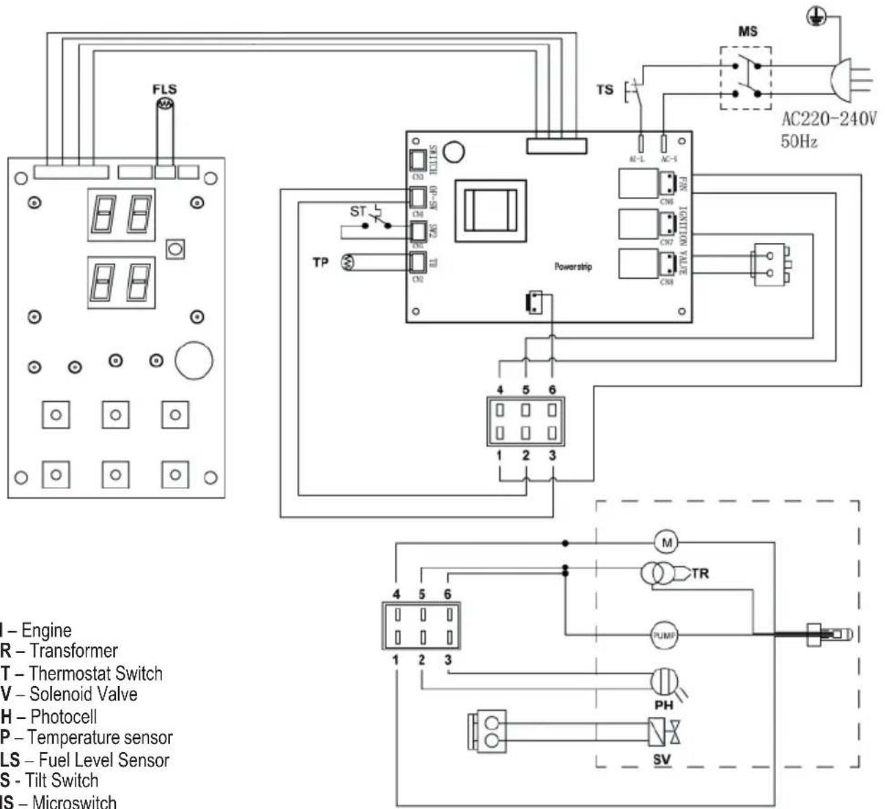
M - Engine
TR - Transformer
ST - Thermostat Switch
SV – Solenoid Valve
PH - Photocell
TP – Temperature sensor
FLS – Fuel Level Sensor
TS - Tilt Switch
MS - Microswitch
PRODUKTMERKMALE
PRODUKTA RAKSTUROJUMS
CARACTÉRISTIQUES DU PRODUIT
Retire a tampa final (P).


