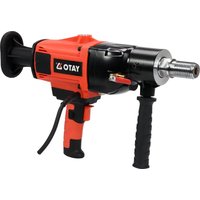
YT-81980 - Drill Yato - Free user manual and instructions
Find the device manual for free YT-81980 Yato in PDF.


| Brand | Yato |
| Model | YT-81980 |
| Product type | Diamond drill (diamond drilling machine) |
| Rated voltage | 230 V AC |
| Rated frequency | 50 Hz |
| Rated power | 2200 W |
| Insulation class | II |
| Rated speed | 1200 rpm |
| Drill bit mount | 1 1/4" UNC |
| Drilling diameter | 12 - 180 mm |
| Compatible drill bit length | 150 - 450 mm |
| Water connection | 1/4" (6.35 mm) |
| Max water pressure | 0.5 MPa |
| Sound pressure level | 90 ± 3 dB(A) |
| Sound power level | 103 ± 3 dB(A) |
| Vibration (ah) | 2.90 ± 1.5 m/s² |
| Protection rating | IP20 |
| Weight | 12 kg |
| Cooling | Water |
| Electrical protection | Integrated PRCD residual current device |
| Overload clutch | Yes |
| Support stand included | Yes |
| Adjustable auxiliary handle | Yes |
| Switch lock | Yes |
| Application | Reinforced concrete, stone, brick, asphalt |
Frequently Asked Questions - YT-81980 Yato
User questions about YT-81980 Yato
0 question about this device. Answer the ones you know or ask your own.
Ask a new question about this device
Download the instructions for your Drill in PDF format for free! Find your manual YT-81980 - Yato and take your electronic device back in hand. On this page are published all the documents necessary for the use of your device. YT-81980 by Yato.
USER MANUAL YT-81980 Yato
natural_image
YATO 3D drill press with black and gray body, no visible text or symbols on the device itself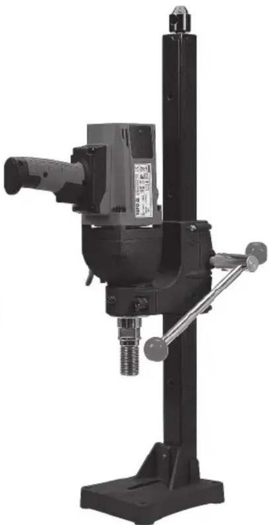
natural_image
Black industrial drill press machine with adjustable shaft and base (no visible text or symbols)CE
PL EN DE RU UA LT LV CZ SK HU RO ES FR IT NL GR
natural_image
Close-up of a hand using a tool to adjust or install a mechanical component, no visible text or symbols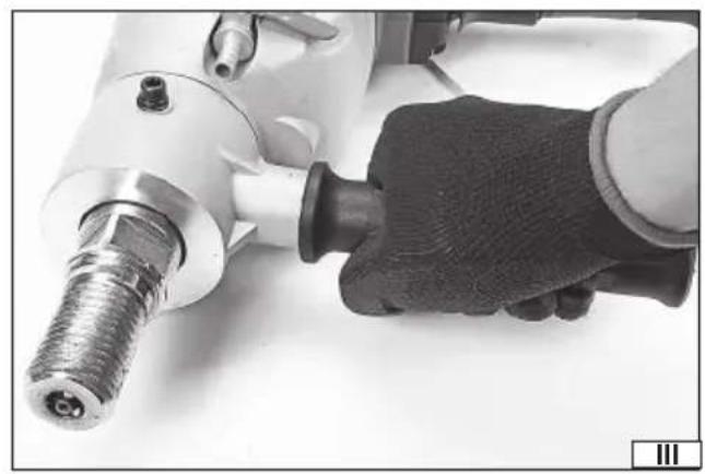
natural_image
Close-up of a hand using a power drill press tool, no visible text or symbols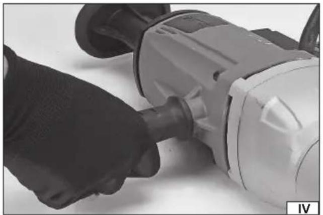
natural_image
Close-up of a hand using a power tool on a mechanical component (no visible text or symbols)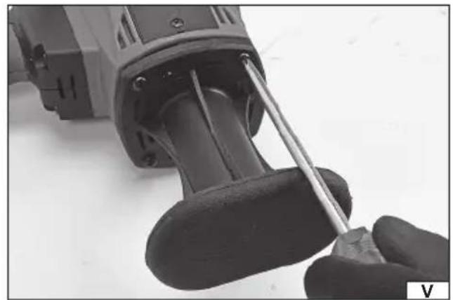
natural_image
Close-up of a hand using a screwdriver to adjust or install a mechanical component (no visible text or symbols)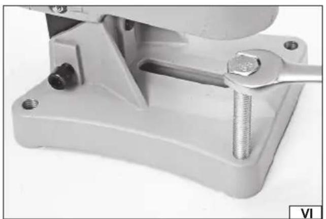
natural_image
Close-up of a mechanical clamp or bracket with a wrench inserted, no visible text or symbols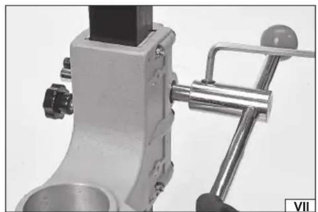
natural_image
Close-up of a mechanical tool or bracket component with no visible text or symbolsnatural_image
Close-up of a hand using a tool to adjust or install a mechanical component (no visible text or symbols)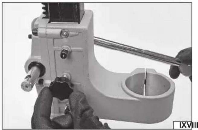
natural_image
Close-up of hands using a tool to adjust or install a mechanical component (no visible text or symbols)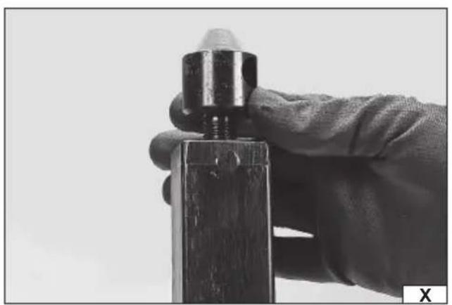
natural_image
Close-up of a hand holding a metal bolt and a wooden block, no visible text or symbols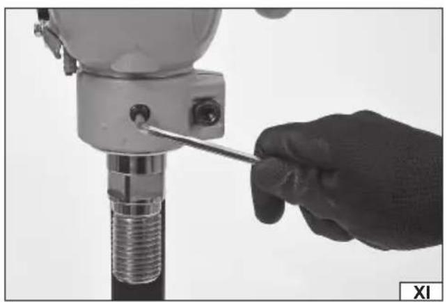
natural_image
Close-up of a hand using a screwdriver to adjust a mechanical component (no visible text or symbols)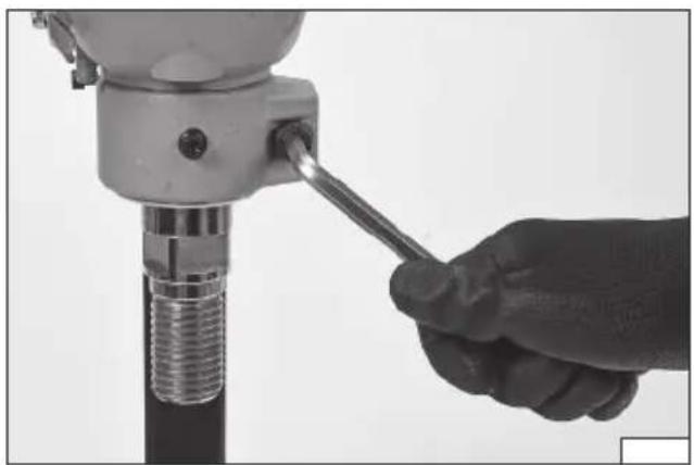
natural_image
Close-up of a hand using a screwdriver to adjust a mechanical drill bit (no text or symbols visible)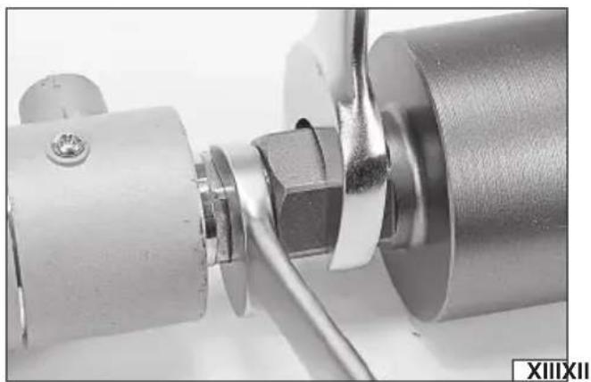
natural_image
Close-up of a mechanical assembly with a metallic cylindrical component and a tool inserted (no visible text or symbols)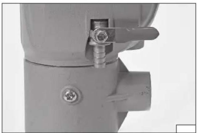
natural_image
Close-up of a mechanical valve assembly with a flanged handle and bolted joint (no visible text or symbols)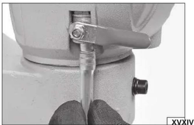
natural_image
Close-up of a mechanical component with a tool inserted, showing no visible text or symbols.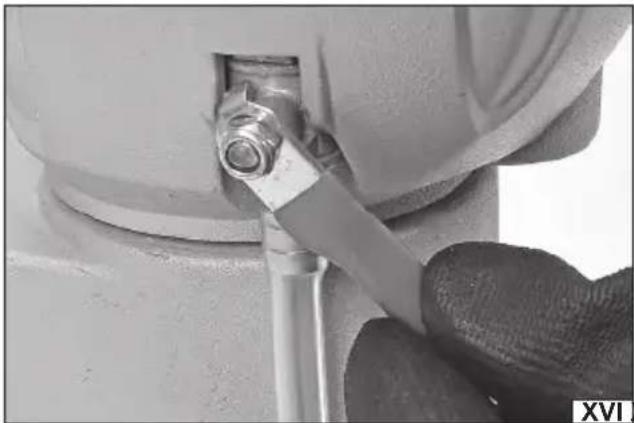
natural_image
Close-up of a hand using a tool to adjust or install a mechanical component, no visible text or symbols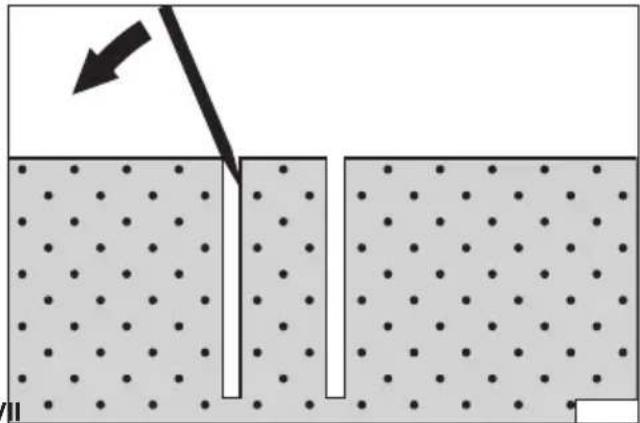
natural_image
Diagram showing a particle interaction with an arrow indicating direction, no text or symbols presentPL
-
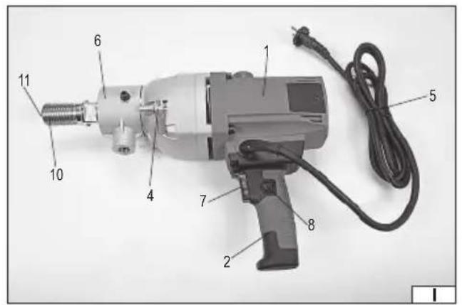
enclosure
-
main grip
-
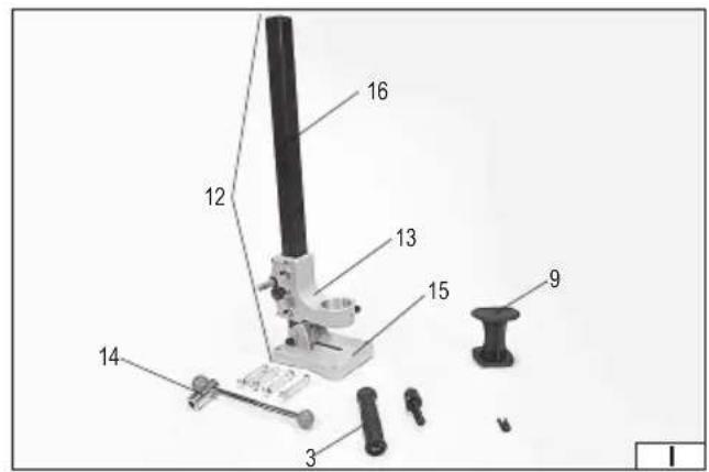
additional grip
-
connection / water valve
-
power supply cable with a plug
-
bracket of the additional grip
-
switch key
-
switch key interlock
-
rear support
-
spindle
-
water outlet
-
rack
-
head of the rack
-
handle of the rack
-
basis of the rack
-
column of the rack
DE
Mains voltage and frequency
Maximum drilling diameter
Second class of insulation
Read the operating instruction
Wear hearing protectors
Wear protective goggles
This symbol indicates that waste electrical and electronic equipment (including batteries and storage cells) cannot be disposed of with other types of waste. Waste equipment should be collected and handed over separately to a collection point for recycling and recovery, in order to reduce the amount of waste and the use of natural resources. Uncontrolled release of hazardous components contained in electrical and electronic equipment may pose a risk to human health and have adverse effects for the environment. The household plays an important role in contributing to reuse and recovery, including recycling of waste equipment. For more information about the appropriate recycling methods, contact your local authority or retailer.
WYPOSAŻENIE PRODUKTU
The diamond drill rig is designed to make holes in reinforced concrete by means of special bits with a diamond cutting edge. It is also possible to use the drill rig to drill holes in ceramic materials such as concrete, asphalt, brick or stone. Due to water cooling option the work is effective and safe. The drill rig can be used as manual or stationary tool. The product is equipped with a rack dedicated for it. Correct, reliable and safe operation of the product depends on proper use of it, hence:
Before commence of operation read the entire manual and keep it.
The manufacturer shall not be responsible for any damages and injuries arising from use of the product in a way contrary to the intended use as well as from failure to observe the safety regulations and guidelines herein. Use of the product contrary to the intended one causes loss of rights to the guarantee and statutory warranty.
EQUIPMENT AND ACCESSORIES
The product is supplied as a whole but it requires some preparatory works described in this manual later. The product is supplied along with a rack, an additional grip with a bracket and a rear support. The product is not supplied with bits and the water connection hose.
TECHNICAL DATA
| Parameter Measurement unit Value | ||
| Catalog no. YT-81980 | ||
| Nominal voltage [V~] 230 | ||
| Rated voltage [Hz] 50 | ||
| Rated power [W] 2200 | ||
| Insulation class II | ||
| Rated rpm [min | ^-1 ] 1200 | |
| Bit socket 1 1/4" UNC | ||
| Min. diameter of the bit [mm] | 12 | |
| Max. diameter of the bit | [mm] | 180 |
| Length of the drill | [mm] | 150 - 450 |
| Diameter of a water connection | ["/ mm] | 1/4" / 6,35 |
| Max. pressure of the outlet water | [MPa] | 0.5 |
| Noise | ||
| acoustic pressure L_wA ± K | [dB(A)] | 90 ± 3 |
| noise power L_wA ± K | [dB(A)] | 103 ± 3 |
| Vibrations a_k ± K | [m/s2] | 2,90 ± 1,5 |
| Protective step | IP20 | |
| Mass | [kg] | 12 |
The declared noise emission value(s) have been measured in accordance with a standard test method and may be used for comparing one tool with another. The declared noise emission value(s) may also be used in a preliminary assessment of exposure.
WARNING! The noise emissions during actual use of the power tool can differ from the declared values depending on the ways in which the tool is used especially what kind of workpiece is processed. There is a need to identify safety measures to protect the operator that are based on an estimation of exposure in the actual conditions of use (taking account of all parts of the operating cycle such as the times when the tool is switched off and when it is running idle in addition to the trigger time).
GENERAL WARNINGS FOR THE SAFETY OF POWER TOOLS
Warning! Read all safety warnings, illustrations and specifications provided with this power tool. Failure to do so may result in electric shock, fire or serious injury.
Keep all warnings and instructions for future reference.
The term "power tool" used in warnings applies to all tools driven by power both wired and wireless.
Workplace safety
Keep the workplace well-lit and clean. Disorder and poor lighting can be causes of accidents.
Do not work with power tools in an environment with an increased risk of explosion, containing flammable liquids, gases or vapors. Power tools generate sparks that can ignite dust or fumes.
Children and third persons should not be allowed to enter the workplace. Loss of concentration can result in loss of control.
EN
Electrical safety
The plug of the electric cable must match the power socket. You must not modify the plug in any way. Do not use any plug adapters with earthed power tools. An unmodified plug that fits the outlet reduces the risk of electric shock.
Avoid contact with earthed surfaces such as pipes, radiators and coolers. Grounding the body increases the risk of electric shock.
Do not expose power tools to contact with atmospheric precipitation or moisture. Water and moisture that gets inside the power tool increases the risk of electric shock.
Do not overload the power cable. Do not use the power cord to carry, pull or unplug the power plug from the power outlet.
Avoid contact of the power cable with heat, oils, sharp edges and moving parts. Damage or entanglement of the power cord increases the risk of electric shock.
In the case of working outside closed rooms, use extension cords intended for work outside closed rooms. The use of an extension cord adapted for outdoor use reduces the risk of electric shock.
When using a power tool in a humid environment is unavoidable as a protection against supply voltage use a residual current device (RCD). The use of RCD reduces the risk of electric shock.
Personal safety
Stay alert, pay attention to what you do and keep common sense while working with the power tool. Do not use a power tool when you are tired or under the influence of alcohol or medication. Even a moment of inattention while working can lead to serious personal injury.
Use personal protective equipment. Always wear eye protection. The use of personal protective equipment such as dust masks, anti-slip safety shoes, helmets and hearing protection reduce the risk of serious personal injury.
Prevent accidental operation. Make sure that the electric switch is in the “off” position before connecting to the power supply and / or battery, lifting or moving the power tool. Moving the power tool with the finger on the switch or powering the power tool, when the switch is in the “on” position can lead to serious injuries.
Before turning on the power tool remove any keys and other tools that were used to adjust it. The key left on the rotating parts of the power tool can lead to serious injuries.
Do not reach and do not lean too far. Keep the right attitude and balance all the time. This will allow easier control over the power tool in case of unexpected work situations.
Dress accordingly. Do not wear loose clothing or jewelry. Keep your hair and clothing away from moving parts of the power tool. Loose clothing, jewelry or long hair can be caught by moving parts.
If the devices are fitted for the connection of dust extraction or dust collection, make sure that they are connected and used properly. The use of dust extraction reduces the risk of dust hazards.
Do not let the experience acquired from frequent use of the tool resulted in carelessness and ignoring safety rules.
Carefree action can cause serious injuries in a fraction of a second.
Use and care of the power tool
Do not overload the power tool. Use the power tool appropriate for the selected application. The right power tool will provide a better and safer job if used according to the designed load.
Do not use the power tool, if the electric switch does not allow switching on and off. Power tool, which cannot be controlled by means of a power switch is dangerous and must be returned for repair.
Disconnect the plug from the power socket and / or remove the battery if it is detachable from the power tool before adjusting, changing accessories or storing the tool. Such preventive measures will allow you to avoid accidentally turning on the power tool.
Keep the tool out of the reach of children, do not let people who do not know how to operate the power tool or these instructions use a power tool. Power tools are dangerous in the hands of untrained users.
Maintain power tools and accessories. Check the tool for mismatches or jams of moving parts, damage to parts and any other conditions that may affect the operation of the power tool. Damage must be repaired before using the power tool. Many accidents are caused by incorrectly maintained tools.
Keep cutting tools sharp and clean. Properly maintained cutting tools with sharp edges are less prone to jamming and are easier to control when working.
Use power tools, accessories and inserted tools etc. in accordance with these instructions, taking into account the type and conditions of work. The use of tools for work other than designed is likely to result in a dangerous situation.
Handles and gripping surfaces must be dry, clean and free from oil and grease. Slippery handles and gripping surfaces do not allow for safe operation and control of the tool in dangerous situations.
Repairs
Repair the power tool only in authorized facilities using only original spare parts. This ensures proper operation safety of the power tool.
DIAMOND DRILL SAFETY WARNINGS
When performing drilling that requires the use of water, route the water away from the operator's work area or use a liquid collection device. Such precautionary measures keep the operator's work area dry and reduce the risk of electrical shock.
EN
Operate power tool by insulated grasping surfaces, when performing an operation where the cutting accessory may contact hidden wiring or its own cord. Cutting accessory contacting a "live" wire may make exposed metal parts of the power tool "live" and could give the operator an electric shock.
Wear hearing protection when diamond drilling. Exposure to noise can cause hearing loss.
When the bit is jammed, stop applying downward pressure and turn off the tool. Investigate and take corrective actions to eliminate the cause of the bit jamming.
When restarting a diamond drill in the workpiece check that the bit rotates freely before starting. If the bit is jammed, it may not start, may overload the tool, or may cause the diamond drill to release from the workpiece.
When securing the drill stand with anchors and fasteners to the workpiece, ensure that the anchoring used is capable of holding and restraining the machine during use. If the workpiece is weak or porous, the anchor may pull out causing the drill stand to release from the workpiece.
When drilling through walls or ceilings, ensure to protect persons and the work area on the other side. The bit may extend through the hole or the core may fall out on the other side.
Do not use this tool for overhead drilling with water supply. Water entering the power tool will increase the risk of electric shock.
USE OF THE PRODUCT
Preparation for the operation.
Unpack the product and remove all elements of the packaging. It is recommended to keep the package for storage and transport of the product. Check product in terms of damages, which could occur during the transport.
Note! Before commence of any preparatory works make sure that the switch key of the product is at the off position and that the product is unplugged from the socket.
The drill rig can be prepared in two variants of operation: manual and on the rack.
If only it is possible use the rack since it makes operation simpler and safer.
Preparation for manual operation
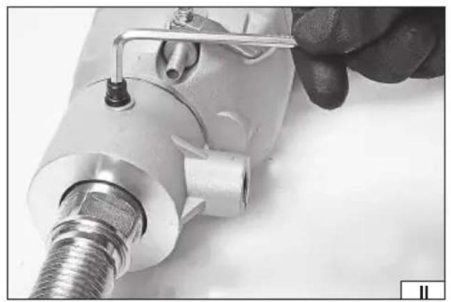
Insert the bracket of the additional grip into the front of the drill rig's body and set it in such a way that the hole in the bracket covers one of the holes in the body and secure it by tightening the screw (II). The ring must not move. Tighten the additional grip into the bracket's socket (III). Such a setting of the main grip and the additional grip is recommended to drill horizontally and at places where space is limited. It requires higher counteracting power preventing unexpected turn of the drill rig.
The additional grip can be also directly tightened into the body opposite to the main grip (IV). Such a setting of the main grip and the additional grip assures better control of the tool during the operation.
Next, install the rear support tightening it by means of screws to the rear part of the enclosure (V).
Preparation for operation on the rack
Base of the rack must be fixed to the floor. Four holes in corners of the base are intended for this (VI). Use all of the holes to fix the rack to the base. Before commence of installation select proper type of the floor. Floor intended for installation must be solid and of uniform structure. Loose and bulk floors such as stone or sand are not permitted. Connecting elements must be adjusted to the floor; one can use raw plugs, anchors, screws and other screwed connecting elements. Do not use hammered connecting elements. Forces produced during drilling can pull out such connecting elements from the floor. Moreover, base of the rack is made from light alloys and it has not been designed to transfer loads occurring when connecting elements are hammered. The base, after it has been fixed to the floor, can be used in any position.
Install the wheel of the movable head of the rack. The wheel can be installed on one or the other side of the spindle of the head. Insert the wheel on the spindle and tighten the screw it in such a way that the wheel is not able to leave the spindle.
Regulate resistance of the head of the rack. To do this one needs to use two screws and the wheel. Using screws regulate a constant resistance. The wheel is used to increase the resistance. Loose slightly the counter nuts and then tighten the screws (VIII) and protect their position by tightening the counter nuts. Tighten the wheel (IX) in order to increase the resistance and untighten it in order to reduce the resistance.
Note! The wheel and screws are not intended to block the head's movement totally. Resistance of the move must be adjusted in such a way to assure the head does not change location when loaded by the drill rig installed in the head, and to assure smooth movement of the head by means of the wheel.
Tighten the plug (X) into the hole at the peak of the column of the rack.
In case there is already installed a ring of the additional grip, dismount it. Dismount also the additional grip if it was tighten directly into the body. The rear support is not necessary to work at the rack. However, if it is installed and it does not generate any problems to use the drill rig at the rack it does not have to be dismounted.
The drill rig must be installed in the head of the rack by inserting it into the bracket of the head. Then turn it till one of the holes in the body covers a hole in the bracket and then secure the drill rig by tightening the screw (XI). Tighten the bracket by means of the screw (XII).
EN
Note! The drill rig must be placed in the head in such a way to assure possibly best access to the main grip and the electric switch. The grip and the power supply cable must not hamper moves of the head.
Installation of the bit
The bit is installed by tightening it into the drill rig's spindle. Thread of the bit must fit the thread of the drill rig. It is prohibited to modify threads in order to adjust them. It is prohibited to use adapters which adjust a bit to the installation system of the spindle. Before installation of a bit check condition of both of the threads - of the bit and of the spindle. Threads must be clean and free from damages. If necessary clean the threads by means of a brush with artificial bristle or a soft cloth.
In the axis of the spindle there is an outlet for cooling water. Check whether it is polluted. It is simpler to do it before the bit has been installed. If necessary clean the water outlet carefully by means of a thin wooden stick or a stick made from the artificial bristle. Do not use sharp, metal objects, which could damage the water supply system. If contaminants cannot be removed contact the manufacturer's authorized center.
Install a bit by tightening it into the spindle in such a way that the spindle thread is totally covered. The connection must be tightened by keeping the spindle by means of one of wrenches and tightening it by means of the other wrench (XIII).
Disassembly of the bit must be carried out by untightening it by means of a wrench while holding it by means of the other wrench. Installation and disassembly of the bit takes place by means of manual wrenches. The bit will tighten itself during operation of the tool which means that disassembly of the bit may require higher forces compared to installation.
Connection of the cooling water
Note! Use water only to cool down. It is prohibited to use other liquids. Water intended for cleaning must be clean and free from any contaminants which could limit or block flow of the water.
If this is possible use the water cooling system. It enables to extend the operation time of bits and the drill rig itself and to reduce quantity of the dust during work. Check whether the water valve of the product is closed and the valve's lever is parallel to the main grip (XIV). Insert a hose of the internal diameter presented in the technical data table into the stub pipe of the valve (XV). Check whether the hose does not slide down the stub during operation. If necessary secure the connection by a bracket. Do not tighten the bracket too much in order to not damage the hose.
Open flow of the water into the valve. Water must be supplied to the water connection under pressure not exceeding the one stipulated in the table with technical data. Check whether connection of the hose on the stub of the valve does not indicate any leaks. Open the water valve by turning the lever in such a way to make it perpendicular to the main grip (XVI).
Check whether water leaves the outlet jet.
Note! In case when the end of the bit at the time of operation becomes higher than the end of the spindle, e.g. when making holes in a ceiling, make sure that the water does not flow into the drill rig. The drill rig is not tightened and contact of the water with the electric systems of the product may result in electric shock which could result in serious injuries including death.
In such a case drill without the water cooling or use an external unit to collect excess of the water (available separately) connected to industrial vacuum cleaner, designed for wet operation (available separately).
Water system must be installed in such a way that it does not hamper operation of the product and it does not prevent access to the grip and switch.
Test of the earth fault breaker
The product is equipped with an automatic earth fault breaker connected to the power cord near the plug. Before commence of the supply its operation must be tested. Make sure that the switch key of the tool is in its off position, the bit has been dismounted and the spindle has no contact with any object. Connect supply cable plug to the network socket. Press the TEST button located at the enclosure of the PRDC earth fault breaker, control lamp at the earth fault breaker is off. Press the RESET button and then start the product by pressing the earth fault breaker, the control lamp must be on.
In case the control lamp does not go off after the TEST button has been pressed or when it goes off immediately after the product has been started, stop operation of the product, unplug the unit and have the machine repaired in an authorized service center.
Note! It is prohibited to use the product with damaged earth fault breaker.
Start of the product
Before commence of operation always carry out an initial start up which enables checking correctness of the product operation.
Make sure that switch key of the tool is in the on position and plug of the power cord is unplugged from the socket.
Install the bit and connect the water flow. Both of the operations must be carried out acc. to the guidelines. Close the water valve. Make sure that the bit has no contact with any object. Insert the plug into the power supply socket.
Press the RESET button on the earth fault breaker and open the water valve.
Press and hold the switch key; it will start the product. The more pressure on the switch key the higher rpm of the bit. Maximal pressing of the switch key results in its nominal rpm value. The product must operate approx. 30 s. with a nominal rotary speed.
At this moment check whether the bit does not show any traces of axial run-out, the product does not vibrate and it does not emit too much noise, there is no smoke or any suspicious odors. Check whether flow of water in the cooling system is not disturbed in any way.
EN
If there are observed any symptoms of improper operation, switch off the product immediately, unplug the power cord from the socket and then try to liquidate a reason for improper operation. If it is impossible to liquidate the reason for improper operation have it repaired in the authorized repair center of the manufacturer.
It is prohibited to operate with the product showing improper operation or when it is damaged.
Switch key interlock
The switch key is equipped with an interlock which enables to block switch key when it is maximally pressed. It enables to carry out operations without holding the switch key. In order to start the interlock press the switch key fully and hold it in this position. Then press the interlock key and release the pressure at the key switch. Release of the interlock takes place by pressing the switch key. It results in release of the interlock. Release of the pressure at the switch key stops the product's operation.
Switching off
The product must be switched off in the following sequence.
Release pressure at the switch key; if the interlock has been activated, deactivate it first.
Wait till rotates of the bit stop. Close the water valve. Unplug the power cord from the socket. Disconnect the water installation from the product. Open the water valve of the product and enable a residue water flow out.
Dismount the bit and start maintenance of the product.
Operation
Before commence of the work always prepare the operation place.
If a passage (through) hole is to be carried out protect also the other side of drilled area since core falling off the bit may cause a hazard.
Check place, where a hole is to be drilled in terms of any obstacles such as installations: water, gas and electric ones, damage to which could result in injuries and a death risk as well as material damages.
If at the time of drilling works certain reinforcement is to be cut, obtain a relevant permit from technical supervision authorities or any other services responsible for safety of structures.
When drilling do not slant the drill rig, it can damage the bit, the tool itself and to result in injuries.
When drilling apply such pressure only which is necessary to drill effectively. Too much pressure shall cause quick wear of the bit and the drill rig itself. It may also cause activation of the overload clutch.
The drill rig is equipped with overload clutch. It operates at the moment the machine detects too much resistance during drilling. Firstly, some pulsation takes place and finally, bit stops despite the engine operates. Operation of the clutch can be caused by too large pressure during drilling, by bending of the bit or drilling a material which requires too high torque.
If the clutch operation is observed release pressure of the bit till the drill rig has returned to proper operation.
In case when no-passage holes are carried out the core stays fixed to the base. After the end of drilling do not switch off flow of the water immediately. It will enable to flush out the dusts produced when drilling, which is located between the wall of the bit and its core.
The core must be unsticked from the base by means of a chisel in a way presented in the illustration (XVII).
In case of no-passage holes the core may fall off from the bit by itself. Before start of the passage drilling protect the other side, e.g. by means of a boarding, in order to prevent the core from falling from the core and making any damages. If the core does not fall from the bit under its own weight, delicately tap the walls of the bit by means of a piece of wood or plastic one. It is prohibited to use metal objects to do this. If it is still impossible to remove the core, one may use an ejecting drift inserted into the installation hole of the bit. Remove the core by light tapping. Stay cautious and do not damage the thread in the installation hole.
Before commence of drilling mark the drilling place, around the drilling mark a circle (diameter of the hole). It enables accurate drilling.
After the end of work close the water flow, unplug the tool and start maintenance operations.
MAINTENANCE AND OVERHAUL
ATTENTION! Before any adjustment, technical service or maintenance operations unplug the tool. Once the operations have been finished, the technical conditions of the tool must be assessed by means of external evaluation and inspection of the following elements: body and handle, conductor with a plug and deflection, functioning of the electric switch, patency of ventilation slots, sparking of brushes, noise level of functioning of bearings and gears, start-up and smoothness of operation. During the guarantee period, the user cannot dismantle the electric tools or change any sub-assemblies or elements, since it will cancel any guarantee rights. All irregularities detected at overhaul or during functioning of the tools are a signal to have the tool repaired at a service shop. Once the functioning has been concluded, the casing, ventilation slots, switches, additional handle and protections must be cleansed with a stream of air (at a pressure not exceeding 0.3 MPa), with a brush or a cloth without any chemical substances or cleaning liquids. Tools and handles must be cleansed with a clean cloth.
DE
PRODUKTBESCHREIBUNG
PRODUKTA RAKSTUROJUMS
PRODUKTA APKALPOŠANA
Darba sagatavošana
CARACTERISTIQUES DU PRODUIT
DEKLARACJA ZGODNOŚCI DECLARATION OF CONFORMITY DECLARATIE DE CONFORMITATE
0925/YT-81980/EC/2025
We declare and guarantee with full responsibility that the following products:
2014/30/UE Electromagnetic compatibility (EMC) Directive
Directiva privind compatibilitatea electromagnetică (EMC) (H.G. nr. 487/2016)
Serial number: concern all serials numbers of item(s) mentioned in this declaration
The person authorized to compile the technical file:


- PL
- DE
- WYPOSAŻENIE PRODUKTU
- Before commence of operation read the entire manual and keep it.
- EQUIPMENT AND ACCESSORIES
- TECHNICAL DATA
- GENERAL WARNINGS FOR THE SAFETY OF POWER TOOLS
- Workplace safety
- EN
- Electrical safety
- Personal safety
- Use and care of the power tool
- Repairs
- DIAMOND DRILL SAFETY WARNINGS
- USE OF THE PRODUCT
- Installation of the bit
- Connection of the cooling water
- Test of the earth fault breaker
- Start of the product
- Switch key interlock
- Switching off
- Operation
- MAINTENANCE AND OVERHAUL
- PRODUKTBESCHREIBUNG
- PRODUKTA RAKSTUROJUMS
- PRODUKTA APKALPOŠANA
- Darba sagatavošana
- CARACTERISTIQUES DU PRODUIT
- DEKLARACJA ZGODNOŚCI DECLARATION OF CONFORMITY DECLARATIE DE CONFORMITATE
Brand : Yato
Model : YT-81980
Category : Drill