Bi2 Cassette - Air-conditioner OLIMPIA SPLENDID - Free user manual and instructions
Find the device manual for free Bi2 Cassette OLIMPIA SPLENDID in PDF.

| Product type | Flush-mounted cassette air conditioner (ceiling) |
| Brand | Olimpia Splendid |
| Model | Bi2 Cassette |
| Dimensions (L x W x H) | 570 x 570 x 285 mm |
| Approximate weight | 28 kg |
| Power supply | 230 V ~ 50/60 Hz - 1 Ph |
| Max. absorbed power | Refer to rating plate |
| Operating temperature | -20 °C to +40 °C (ambient air) |
| Operating humidity | 10% to 90% RH (non-condensing) |
| Max. operating pressure (water) | 15 bars |
| Max. water temperature | 75 °C |
| Min. water temperature | 3 °C (with glycol) |
| Motor | EC brushless with driver/inverter |
| Fan | Radial with aerodynamic profiled blades |
| Air filter | Honeycomb polypropylene nanofibers, easily removable |
| Condensate pump | Centrifugal with check valve and 2-level float |
| Main functions | Heating, cooling, ventilation, air renewal (option) |
| Installation | Ceiling mounting, max. height 3.5 m from floor |
| User maintenance | Clean the air filter every month (washable with water) |
| Technical maintenance | Annual inspection by qualified professional |
| Safety | Mandatory grounding, omnipolar switch, do not use by children under 8 years without supervision |
| Spare parts | Use only original parts - contact authorized after-sales service |
| Warranty | Void in case of unauthorized modifications or non-compliant installation |
| Standards | EEC directives, ecodesign |
Frequently Asked Questions - Bi2 Cassette OLIMPIA SPLENDID
User questions about Bi2 Cassette OLIMPIA SPLENDID
0 question about this device. Answer the ones you know or ask your own.
Ask a new question about this device
Download the instructions for your Air-conditioner in PDF format for free! Find your manual Bi2 Cassette - OLIMPIA SPLENDID and take your electronic device back in hand. On this page are published all the documents necessary for the use of your device. Bi2 Cassette by OLIMPIA SPLENDID.
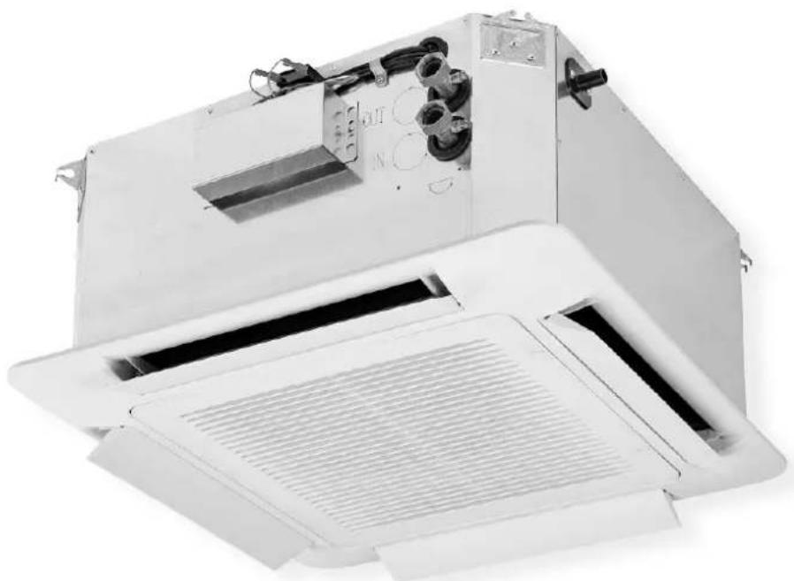
USER MANUAL Bi2 Cassette OLIMPIA SPLENDID
(Brushless + Driver/Inverter)

natural_image
Exterior view of a white industrial air conditioner unit with ventilation ducts and control panel (no visible text or symbols)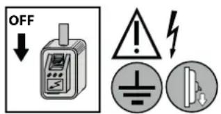
ACCESSORI
natural_image
Illustration of a two-story rectangular pallet with horizontal straps, no text or symbols presentnatural_image
Illustration of a forklift lifting a box, with no text or symbols presentnatural_image
Silhouette of two figures exchanging a block with the number 25 (no text or symbols beyond the number)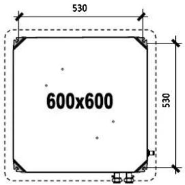
natural_image
Technical diagram of a mechanical assembly with a bolt and nut, enclosed in a circle (no text or labels)Fissaggio pannello:
natural_image
Pure diagram of a square frame with four arrows indicating direction, no text or symbols present
natural_image
Close-up of a mechanical device with arrows indicating directional flow or movement around a central fan (no text or symbols visible)Unità 2 tubi
Unità 4 tubi
- PER PULIRE L'UNITÁ:
(Brushless + Driver/Inverter)

natural_image
Exterior view of a white industrial air conditioner unit with ventilation ducts and control panel (no visible text or symbols)INSTALLATION, USE AND MAINTENANCE MANUAL EN
Given the constant evolution of the product, these instructions may be incomplete and/or not up to date. For anything not covered, in the event of mistakes, doubts regarding interpretation and/or any other reason that may need confirmation, refer to the pre-sales and post-sales documentation on the manufacturer's website, which is always updated, complete, and translated into a range of languages.
Total or partial reproduction of this "Installation, Use and Maintenance Manual" is prohibited.
- The technical data, styling, components and accessories described in this manual are not binding. The manufacturer reserves the right to make any changes deemed necessary to improve the product (technical data, performance, dimensions, etc.), at any time without prior notice.
- The references to laws, standards or technical rules in this manual are purely for information purposes, and were valid on the date on which this manual was printed. If new regulations or amendments to current laws enter into force, this shall not constitute grounds for any obligation of the manufacturer with regard to third parties.
- The manufacturer is responsible for ensuring that its product conforms to the construction laws, directives and standards in force at the time the product is sold. Knowledge and compliance with legal provisions and standards regarding system design, installation, operation and maintenance are the exclusive responsibility of the designer, installer and user, in their respective areas of expertise.
- WARNING! It is important to check that the design and installation conform with current standards (EN norms, safety standards, local regulations) and are approved, where appropriate, by the competent control authorities.
- To use the unit correctly and safely, the installer, user and maintenance technician must strictly follow the instructions in this manual that are relevant to their respective areas of expertise.
- For further information on additional accessories, refer to the instruction sheet (supplementary instructions to this manual).
- All operations that involve exposure to risks (installation, first start-up, maintenance, troubleshooting, etc.) must be carried out by qualified personnel.
- Read all the information in this manual thoroughly: it contains important indications regarding safety during installation, operation and maintenance.
- Pay particular attention to the operating rules marked with "DANGER" or "WARNING" signs as failure to observe them can lead to property damage and/or personal harm.
- For any malfunctions not mentioned in this manual, contact the local After sales Service immediately or contact the manufacturer directly.
- Always keep this manual with the unit.
- This manual is an integral and essential part of the product and must be given to the user.
- Should the unit be sold or transferred to another owner, always ensure that the manual remains with the unit for use by the new owner and/or installer.
- Keep this manual in a dry location to avoid deterioration, for at least 10 years for any future reference.
- The manufacturer shall not be held liable for any damage whatsoever caused by improper use of the unit, and partial or superficial knowledge of the information contained in this manual.
EACH UNIT IS SUPPLIED WITH ITS OWN SPECIFIC (AND UNIQUE) WIRING DIAGRAM. REFER ONLY TO THAT ONE!
TECHNICAL DATA AND ELECTRICAL ABSORPTION:
REFER TO THE VALUES/DATA ON THE SERIAL NUMBER LABEL APPLIED TO THE UNIT.
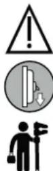
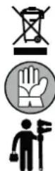
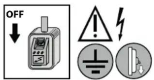
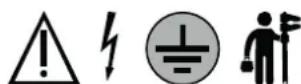
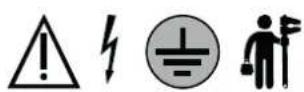
SAFETY SYMBOLS
| WARNINGDanger!!! | |
| DANGER:Power supply | |
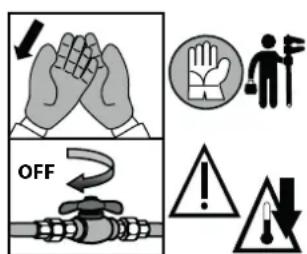
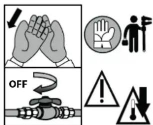
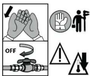
| DANGER:High temperature | |
| DANGER:Moving parts | |
| PROHIBITED | |
| MANDATORY:Earthing point |
| MANDATORY:Use forklift | |
| MANDATORY:Qualified personnel only | |
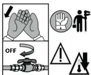
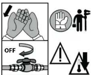
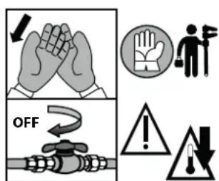
| MANDATORY:Use protective gloves | |
| MANDATORY:Cut off power supply | |
| MANDATORY:Consult the manual | |
| WEEE provisions(waste disposal) |
SAFETY REQUIREMENTS
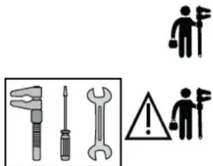

Observe the following safety rules when installing, starting up, using and servicing the units:
- Installation must be carried out by professionally qualified personnel in strict compliance with the current standards in the country where the equipment will be used, as well as the manufacturer's instructions.
- Installation, first start-up and maintenance of the unit can be carried out by qualified, trained personnel only.
- Professionally qualified personnel are those with specific technical experience in the field of heating and cooling system components. In any case, telephone the manufacturer to receive all necessary information.
- Install the air ducts, chilled water lines, hot water lines, electric power lines, etc. with all their regulation, cut-off and safety devices according to the installation project.
- Always make sure that the unit and all its electrical parts have been correctly earthed prior to starting up the unit.
- Do not expose the unit to flammable gases.
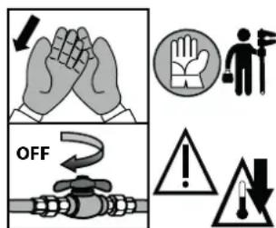
If the unit is to be mounted/removed/maintained:
- Use special protective gloves.
- Beware of sharp edges inside the unit.
- Beware of sharp edges outside the unit.
- Cut off the power to the unit.
- Wait until the moving parts of the unit are all stationary.
- Make sure that the inlet water valve is closed.
- Wait until the heat exchanger has cooled down.
- Always keep the air intake and supply grilles clear.
- Never use the unit to support other equipment.
- Never leave tools, spare parts, elements that are loose or not properly secured, etc. inside the unit.
- Make sure that all inspection panels are closed properly: make sure that all screws are tightened perfectly.
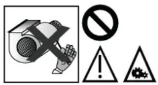

- For units with accessible fans (concealed versions and versions intended to be connected to air ducts), do not start the unit until it is enclosed within a compartment accessible only with the use of tools.
- Fans can exceed speeds of 1000 rpm. Do not insert any objects or hands into electric fans.
- We recommend installing an omnipolar safety circuit breaker near the unit, which can be easily reached to cut off the power. Before any cleaning or maintenance, cut off the power to the unit.
- Before opening the unit, make sure that all electric supplies have been cut off. In particular, make sure that the fan is off and cannot be started inadvertently prior to opening inspection panels.
- CHECK THE EARTH CONNECTION!!
- This unit may be used only for the purpose for which it is intended: heating, cooling, ventilation and air treatment of domestic, residential, commercial and industrial sites in which the air condition can be considered good/standard/normal. It should be used only for treating air with “civil” temperatures and low levels of pollutants, industrial fumes, chemical fumes, salts, powders, oils, fats, relative humidity (R.H.) and aggressive substances. Any other use must be considered improper and therefore dangerous, (besides starting corrosion/abnormal wear, bonding/binding/locking motors/fans/bushings/bearings and moving parts, obstructing filters/coils/etc., and therefore dramatically reducing the efficiency and life of the unit).
- The main risks arising from improper maintenance and/or use are mostly electrical (short circuit, electric shock, overheating and igniting fire), thermal (overheating and igniting fire), mechanical (projection of moving parts, overheating due to friction and consequently igniting fire) and water-related (water leakage, flooding and damage to structures and furnishings).
- In particular, the standard unit is not suitable for use in the agricultural sector (e.g. greenhouses with high R.H., fertilizers, nitrogen, chemicals and pesticides sprays, etc.), salty environments and the livestock sector (e.g. farms with acid atmospheres, high R.H., nitrogen, ammonia, sewage, biogas, etc.), food industries (air with high levels of volatile organic compounds, acid vapours, chlorides, yeasts, etc.), marine areas (air with high levels of chloride, salt, corrosive substances, etc.).
For similar applications, ask for specific units that are designed for a specific use (e.g. units with a high IP level, ATEX units, units with condensate drain pan and/or casing and/or coil and/or other components made of AISI304L or AISI316 stainless steel, are painted, etc.). - Beware when starting up units: do not start units on sites where other operators are still finishing construction site work (mounting/cutting/smoothing/painting plasterboard/floors/false-walls/furniture/furnishing/etc., and construction work in general): the atmosphere may be full of different types of dust and pollutants (including chemicals) that could quickly damage the unit, even seriously.
- Should the unit work in a house where disabled people and/or children and/or animals live, it must be located safely out of their reach. Always make sure that the access door to the inside control board remains locked.
- The unit can be used by children older than 8 years or by people with diminished physical, sensory or mental capacities, or those without experience or the necessary knowledge, provided they are supervised or have received instructions on using the device safely and are aware of the risks it poses. Children must not play with the unit. Cleaning and maintenance intended to be carried out by the user must not be done by children without supervision.
- Wrong installation may cause harm to people or animals, or damage to property for which the manufacturer will not be held liable.
- The manufacturer shall not be held liable for any damage caused by improper, incorrect or unreasonable use.
- In the event of failures or malfunctions, deactivate the unit and do not attempt to repair it, but ask for the assistance of the installer.
- If you are going to leave the unit off for a long time, first make sure that it cannot harm anyone in any way.
- PLEASE DO NOT FORGET THAT THE WARRANTY CANNOT BE APPLIED IN THE EVENT OF ELECTRICAL OR MECHANICAL MODIFICATIONS, OR TAMPERING IN GENERAL!!
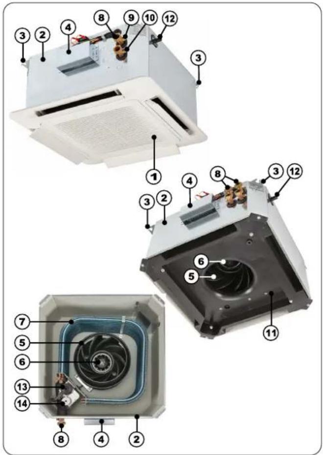
MAIN COMPONENTS
- Cover panel, made of ABS, with Central air intake grill and no. 4 manually adjustable air supply side flaps.
- Bearing structure made of thick galvanized sheet steel with holes for fixing to the wall/ceiling + internal thermal-acoustic insulation (class M1)
- External brackets on the 4 corners for easy fixing to the roof.
- Electric terminal board with cover for connection with remote control (remote control is an accessory),
- Radial fan with wing profile blades
- Electric motor, 230V-1Ph-50Hz directly coupled to the fan (AC or EC)
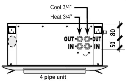
- Heat exchanger coil (1 coil for 2-pipe units - 1 coil for 4-pipe units)
- Coil water connections
- Manual air vent valve
- Manual water drain valve
- Air conveyor and drain pan made by ABS
- Condensate drain
- Centrifugal type condensate pump, including floater and no-return valve avoiding frequent on/off
- 2-level floater: the 1st for the control of the condensate level, the 2nd for alarm activation
• Air filter easy to remove, made of a metal frame holding filtering section made of high efficiency polypropylene NAN cellular fabric net
ACCESSORIES
• Large range of control panels, I.R. control e regulation systems
• Regulation valves (2 and 3 ways, on/off and modulating)
• Electrical heater with Power relay and Safety thermostat
• Auxiliary drain pan
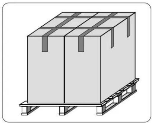
PACKAGING
natural_image
Illustration of a two-story rectangular pallet with metal racks and a flat base (no text or symbols)The units are shipped with standard packaging consisting of a cardboard (and/or nylon) box and pallets.
The accessories are supplied loose, packed separately or already mounted on the unit (on request).
Inside the packaging there is an envelope containing the installation, use and maintenance manual.
DOCUMENTATIONS AND LABELS
A serial number label (unit identification) bearing the following data is applied to each unit:
- Manufacturer's data
- Unit model and serial number
- Technical data and general information
The wiring diagram is provided on an additional label or additional paper sheet.
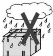
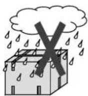
TRANSPORT, RECEIPT, HANDLING
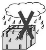
Do not get wet
Do not trample

natural_image
Simple line drawing of a forklift lifting a box, no text or symbols presentDo not leave packages loose during transport

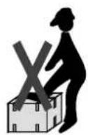
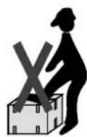
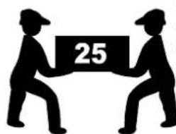
natural_image
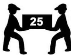
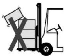
Silhouette of two figures exchanging a block with the number 25 (no text or symbols beyond the number)Do not handle the unit alone if it weighs more than 25 kg
- The transport must be done as follows:
- Packages must be securely fixed to truck floor.
- Packages must be covered.
- Do not stack the following on top of the unit: other units, equipment, packages or objects.
- The unit has special protective packaging for transport and delivery, which must be kept in good condition until the unit is positioned where it will be installed.
- Make sure that the unit has all its parts, as specified in the order.
- Check for any damage and that the unit code is the same as that of the ordered model.
- Every unit is factory tested before shipment, so report any damage immediately to the carrier.
- Shipping, unloading and handling are all operations to be carried out very carefully in order to avoid damaging the goods. Do not use the unit components as handholds. Ensure that the lifting capacity of the equipment is adequate for the unit weight. Make sure that the unit is in stable equilibrium before starting the lifting/handling.
- When lifting, bear in mind that the centre of gravity of the unit may be off-centre.
- The choice of equipment and handling method will depend on various factors, such as: the unit weight; unit type and overall dimensions; handling place and route (dirt site, asphalted yard, etc.); condition of the destination place (roof, yard, etc.); distances, drops and gradients (uneven routes, ramps, steps, doors).
TRANSPORT, HANDLING, STORAGE ON SITE
- Do not stack the following on top of the unit: other units, equipment, packages or objects.
- Keep in a dry place: the units must be transported and stored indoors!
- Keep away from: direct sunlight, rain, snow, sand and wind.
- Storage and transport temperature limits: -20°C...+60°C; max 90% R.H.
INSTALLATION: UNIT LOCATION
- MANDATORY:
Installation of the unit and all accessories can be carried out only by specialist qualified personnel, according to the regulations and laws in force, including the local ones in the country of installation.
EN - 6
Before proceeding with installation:
- Check that the unit and its technical characteristics match those in the design or other documents.
- Always keep packing out of the reach of children and/or disabled people and/or animals, as it may be harmful.
- Wear suitable protective clothing before installing the unit. Use suitable equipment to prevent any accidents during installation. Carry out all operations in accordance with the safety laws/regulations in force in the country of installation.
- Before installing the unit, we recommend mounting any separate optionals on the unit, following the assembly instructions contained in each single kit.
Installation:
- Decide the installation location. Position the unit on a solid structure that does not cause vibrations and is able to bear the weight of the machine.
- Do not install the unit in a space exposed to sunlight or heat sources, vapor or flammable gas.
- Install the unit so that the inlet and outlet air ducts are not obstructed; the air must circulate freely throughout the area that has to be air-conditioned.
- Install the unit in an easily accessible location, not to hinder the maintenance operations.
- For the correct operating, the maximux installation height of unit from the floor have to be 3.5 meters.
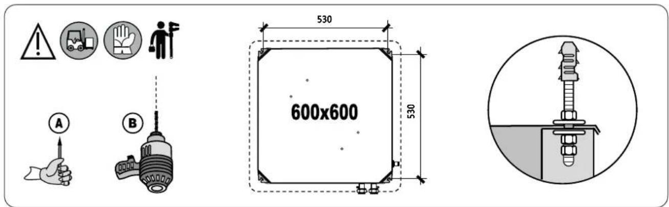
Unit fixing:
The location of the unit installation must be chosen so that all around the unit perimeter there is a space of at least 100 cm existing system (electrical or hydraulic).
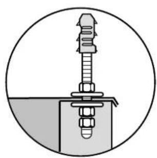
The unit must be fixed to the ceiling by the means of threaded rods with anchors adjusted according to the type of structure (to be provided by others) as described:
- The 4 holes positions in the structural ceiling must first be marked (A) and the holes for the threaded rods must then be drilled (B).
- The threaded rods must be securely fixed in the ceiling (their length depends on the distance between the ceiling and the structural ceiling)
- The unit must be lifted inserting the threaded rods in correspondence with the fixing slots and then blocked, using adequate washers and nuts.
- Verify, using a spirit level, that the machine is perfectly horizontal and then fix the nuts and locknuts.
- Due to its weight, the unit should be lifted with mechanical equipment.
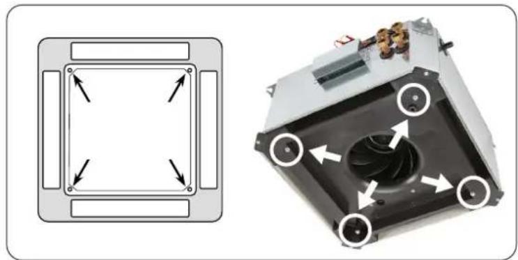
Panel fixing:
Fixed tightly the unit, the plastic panel must be mounted using only and exclusively the screws provided.
To prevent the deformation of the grid, be careful not to overtighten the screws.
natural_image
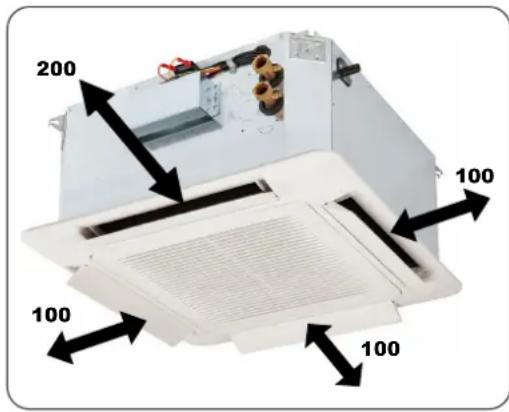
Technical diagram showing a square component with directional arrows and a 3D view of a mechanical device with internal components (no text or symbols)INSTALLATION: MAINTENANCE ACCESS SPACE

- The unit must be installed in such a way as to guarantee full accessibility for routine and special maintenance, including easy replacement of any component and/or replacement of the entire unit. The manufacturer shall not be held liable for any costs or expenses incurred as a result of failure to comply with these requirements.
- Any false ceilings must allow removal of the bottom and front panels on the unit for inspection and maintenance, and to replace the filters, fans, coil, regulation devices and electrical equipment.
- On the water connection side of the unit, leave at least 200 mm for installing the pipes and valves.
- For the other 3 sides of unit leave at minimum 100 mm free space for inspection/maintenance.
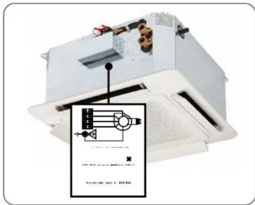
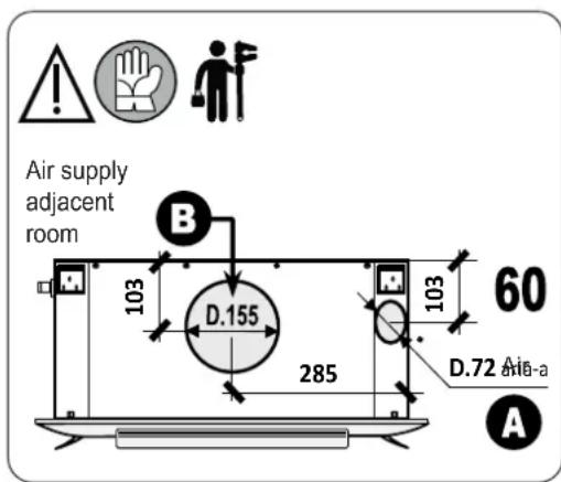
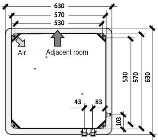
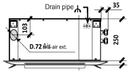
INSTALLATION: DUCT CONNECTIONS
Renewal system and remote air distribution
The side openings allow the separate realization of an external air intake duct for the renewal and of an air hose duct for an adjacent room.
Fresh air
Remove the film on the sheet indicated with letter "A".
Use the flange ∅72mm (optional) and connect the pipe with anti-condensate insulation; the use of a fan for the duct (optional) must be provided with non-return valve and filter to prevent dust.
Remote air distribution
Remove the film on the sheet indicated with letter "B".
Use the flange ∅155mm (optional) e connect the pipe for air distribution in the adjacent room.
It is recommended the closing of the air vent on the panel in correspondence of the duct of remote air distribution.
- The ducts must be sized according to the system and air flow characteristics (ESP) of the unit fans. Miscalculating the ducts would cause loss of power or could trigger devices in the system.
- In order to attenuate the noise level, the use of cased air ducts is recommended.
- The initial section of the air supply duct should be twice as long as the shorter side of the duct before curves, branches or obstructions such as shutters, otherwise the unit performance will suffer.
- Branching sections should not be angled by more than 7^ .
In compliance with the European ECODESIGN directives and regulations, the ducts must be properly sized (large sections, few and slight changes of direction, etc.) in order to guarantee low pressure drops (pressure drops are always a source of waste and energy dissipation, with consequent loss of performances and energy efficiency in the unit and in the system in general).
- The air intake and supply ducts must always have a larger section (or the same, but never smaller) than the air intake or outlet on the unit, otherwise the @ESP performance will drop (due to air pressure drops).
EN - 8
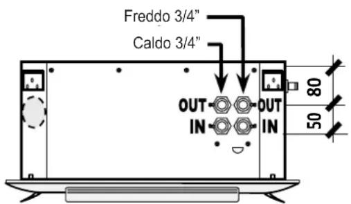
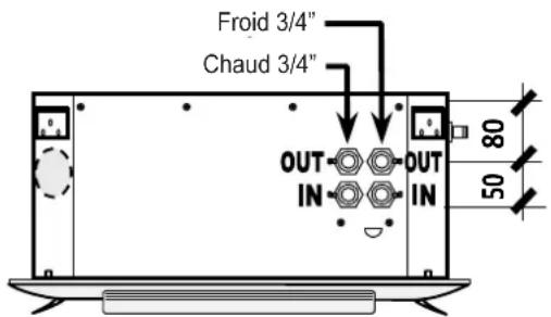
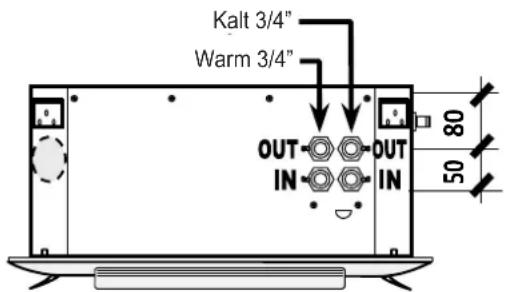
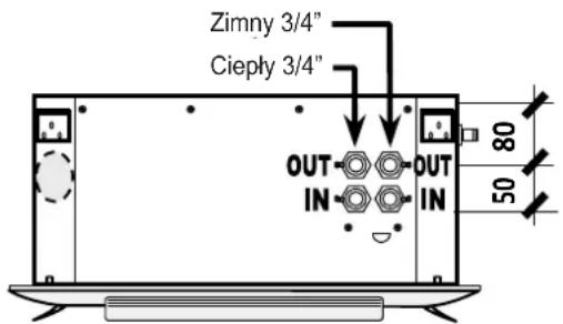
INSTALLATION: WATER SUPPLY CONNECTIONS
- WARNING:
when connecting the coil to the pipes, always use anti-torsion systems (e.g. a spanner and counter-spanner), and tighten with the correct tightening torque, to avoid breaking the coil.
For water coil versions: Make the water connections
- In compliance with the European ECODESIGN directives and regulations, the pipes must be properly sized (large sections, etc.) in order to guarantee low pressure drops (pressure drops are always a source of waste and energy dissipation, with consequent loss of performances and energy efficiency in the unit and in the system in general).
- The water connections must be made using pipes with a larger diameter (or at least equal, but never smaller) that the water connections on the unit!
- Install shut-off valves (of suitable dimensions, MIN 3/4") to isolate the coil from the rest of the circuit in the event of special maintenance. Connect the inlet with a shut-off ball valve and the outlet with a balancing or lockshield valve (or install 2 shut-off ball valves).
- Install a breather valve above and a discharge valve below.
- Mandatory: appropriately insulate water valves and pipes to prevent dripping in cooling mode.
- The water heat exchanger coils are tested at a pressure of 30 Bar, and can therefore operate at a maximum pressure of 15 Bar.
| Tightening torque (Min .... Max) | |
| Unit (coil connection) A 3/4": 10...14 Nm | |
| Regulation valve B 3/4": 8...12 Nm | |
| Ball/lockshield valve C 3/4": 2...4 Nm | |
Please note that the main causes of coil failure are:
- Breakage/cracking of welds or pipes due to abnormal mechanical shock (e.g. impact and/or forcing during handling, transport and especially during installation), in particular forcing during assembly caused by tightening too vigorously without the use of anti-torsion systems such as a spanner and counter-spanner.
- Excessive thermal expansion of the water supply pipes (different temperature between hot/cold water), expansions that in certain circumstances (e.g. pipes that are too long) may become evident and therefore dangerous if they discharge on the unit manifolds.
- Weights, transmission of vibrations or deformations of the pipes in the supply system acting on the unit manifolds.
- MANDATORY: therefore, depending on the features of the system (to be evaluated on a case-by-case basis), use brackets, expansion joints, anti-vibration systems and all other precautions required to prevent the weights, deformations and vibrations of the return pipes from acting on the unit manifolds.
Risk of freezing:
Install antifreeze devices if the unit, drain or plumbing connections may be subject to temperatures close to 0^ C (e.g. protect the pipes with heating cables under the insulation, insulate the pipes, etc.). If the unit is installed in areas with particularly cold climates, empty the water from the system during long system shutdown periods.
INSTALLATION: CONDENSATE DRAIN
For versions used in cooling with condensate generation:
- Mandatory: appropriately insulate condensate drain pipes to prevent dripping in cooling mode.
- Install an appropriately sized condensate drainage system, position it to favour drainage (min. 3% slope), and ensure it has no rising or narrow sections in order to allow regular outflow.
- Mandatory: install a siphon in condensate drainage system.
- Connect the condensate drain to rainwater drainage system.
- Do not use waste water or sewage drains to prevent unpleasant odours from returning into the room if the water in the siphon evaporates.
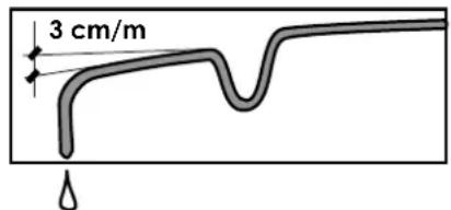
The drainage system should feature an adequately sized trap to:
- Allow the condensate to drain freely.
- Prevent inadvertent entry of air into the circuit under negative pressure.
- Prevent inadvertent leakage of air from the pressurized circuit.
- Prevent entry of unpleasant odours and insects.
- NOTE:
The trap should have a plug to facilitate cleaning of the lower section, and be easy to disassemble.
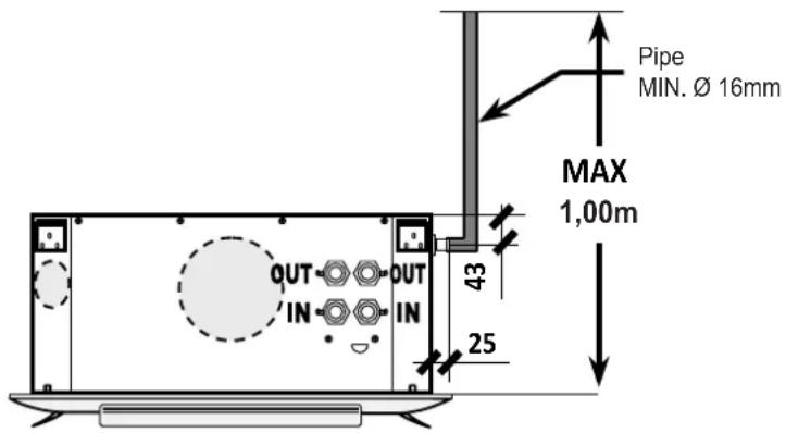
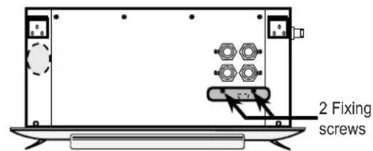
AUXILIARY DRAIN PAN MOUNTING (optional)
The auxiliary drain pan collects the condensate formed near the water connections and the valves.
Fix the auxiliary drain pan to the structure with the 2 screws provided in the position shown in figure, making sure pipes and insulation do not tilt it, hindering the drain.
INSTALLATION: ELECTRICAL CONNECTIONS
- UNIT MANUFACTURED in ACCORDANCE WITH THE EEC ELECTRICAL STANDARDS IN FORCE (SEE THE DECLARATION OF CONFORMITY)

- MANDATORY:
the electrical connections, installation of the unit and all accessories can be carried out only by specialist qualified personnel, according to the regulations and laws in force, including the local ones in the country of installation.
- WARNING:
the unit must be electrically connected: The electrical system must conform to a project drafted by a qualified designer, and documented and approved according to the regulations and laws in force. A few general
EN - 10


(non-exhaustive) prescriptions are given below. Refer to the electrical system design for further details.
- WARNING:
make sure that electrical power to the unit is turned off before carrying out any work.
- Please do not forget that the warranty cannot be applied in the event of electrical or mechanical modifications, or tampering in general.
- Observe the EEC safety regulations and the regulation/laws in force in the country of installation.
- Make sure that the mains specifications comply with the data indicated on the unit identification label.
- Power supply for the unit and accessories (motor, electric heater, remote controls, regulation, etc.): Check that the mains supply voltage is within the established limits (see operating limits).
- Operating the unit with voltages that are not within the aforementioned limits invalidates the warranty.
- Make sure that the electrical system is able to supply the current required by the electrical household appliances already in use in addition to the working current required by the unit.
CHECK THE EARTH CONNECTION
- The unit is electrically safe only when it is correctly connected and properly earthed according to the safety standards in force.
- When making the connection, the earth cable must be longer than the live ones. It will be the last cable to come away if the power cable is accidentally pulled, thus ensuring good earth continuity.
CONNECTION CABLE SPECIFICATIONS
- Make all connections to the unit using cables of adequate size for the power used in accordance with the local laws in force. Their size must be such that the phase voltage drop is less than 3% of the nominal voltage.
- Use H05V-K or N07V-K cables with 300/500V insulation in pipes or ducts.
- For units with an inverter/driver or other frequency-varying device, use shielded cable.
- All cables have to be in pipes or ducts until they are in the terminal board of the unit.
- The cables must not be pulled or twisted as they leave the pipe/duct. They must be protected from the weather. Always use stranded cables with ferrules. Make sure that all individual strands are correctly inserted in the ferrule.
ELECTRICAL CONNECTION AND OMNIPOLAR RESIDUAL CURRENT CIRCUIT BREAKER
- ALL WIRING DIAGRAMS ARE SUBJECT TO UPDATE:
IT IS ADVISABLE TO REFER TO THE WIRING DIAGRAM ACCOMPANYING THE UNIT.
- It is mandatory to rely on a designer and use first class, certified components suited to the specifics of the system in which they must be installed, and to the characteristics of the components mounted on the unit/accessory to be powered.
- Make the electrical connections according to the unit wiring diagram.
- The use of adapters, multiple sockets and/or extension cords is not permitted for main power supply to the unit
- To prevent short circuits, the unit should be connected to the power supply line via an appropriate omnipolar residual current circuit breaker with a minimum contact opening of 3 mm. This circuit breaker is intended to ensure adequate overload protection (thermal part) + short-circuit protection (magnetic part) + protection against electric leakage, electric shock or earth fault (residual current part). See the electrical absorption on the unit label to choose the most suitable circuit breaker.
- Remember: an omnipolar circuit breaker is a switch capable of opening both the phase and neutral. This means that when the switch is opened, both contacts are open.
- The omnipolar circuit breaker or the plug (connection by means of cable and plug) must be mounted where they are easy to reach.
- It is always advisable to install an additional fused cut-off switch upstream, that besides offering additional protection, completely isolates the electric line with a contact gap of at least 3 mm when the fuses are removed.
- The installer is responsible for installing the unit as close as possible to the main power cut-off switch!!
- ELECTRICAL ABSORPTION:
Refer to the electrical absorption on the unit serial number label.
Accessories, remote controls:
When installing the control panel, choose an area where the maximum and minimum ambient temperature limits are respected (0–45°C, < 85% R.H.). Do not install the control panel on a metal wall if it is not permanently earthed.
DIMENSIONS AND TECHNICAL DATA

OPERATING LIMITS
| MAXIMUM electrical absorption Value specified on the unit serial number label | |
| Power supply (unit) | 230Vac ± 10% - 1Ph – 50/60Hz(min 207 .... max 253Vac) |
| Power supply (remote control) | 230Vac ± 10% - 1Ph – 50/60Hz(min 207 .... max 253Vac) |
| Working temperature (ambient air) -20°C ... +40°C | |
| Working humidity (ambient air) 10% ... 90% R.H. (non-condensing) | |
| Maximum water inlet temperature 75°C (NO superheated water; NO steam) | |
| Minimum water inlet temperature | 3°C (with glycol). For lower temperatures, it is mandatory to adopt coil defrosting systems |
| Maximum water flow (Qw.max) | Nominal water flow x 2 (higher Qw means high water speed, noise, high IN/OUT differential pressures). |
| Minimum water flow (Qw.min) | Nominal water flow x 1/3 (lower Qw means low pressure drops, laminar motion, drastic reduction in performance) |
| Maximum working pressure (water) 15 Bar | |
| Ethylene glycol (maximum percentage by weight) | 80% |
| Operation with superheated water NO | |
| Operation with steam NO | |
| Direct expansion operation NO | |
AVERAGE MINIMUM WATER TEMPERATURE (FOR UNITS USED IN COOLING)
To prevent the formation of condensation on the external structure of the unit, the average water temperature should not drop below the limits given in the table below; the limits depend on the humidity conditions and temperature of the ambient air. The above limits refer to units operating at minimum speed (most critical conditions).
| Dry bulb ambient air temperature(°C d.b.) | ||||||||
| 21 23 | 25 27 29 | 31 | ||||||
| MINIMUM AVERAGE WATER TEMPERATURE (°C) | Wet bulb ambient air temperature(°C w.b.) | 15 | 3 3 3 3 | |||||
| 17 | 3 3 3 3 | |||||||
| 19 | 3 3 3 3 | |||||||
| 21 | 5 4 3 3 3 | |||||||
| 23 | 7 6 5 5 | |||||||
When the requested ambient temperature is reached, if the fan stops while chilled water is still circulating in the coil, condensation may form on the external structure of the unit.
To prevent condensation from forming on the external structure of the unit, provide regulation that, in addition to stopping the fan when the ambient temperature is reached, also stops the water supply (3-way valve, 2-way valve, pump OFF, chiller OFF, etc.) or provide additional thermal insulation on the unit.
FIRST START-UP
- MANDATORY:
The first unit start-up and the relative tests must be performed only by specialist qualified personnel.
Before starting the unit, check the following points:
- That the unit has been anchored to the building structure (ceiling, roof, etc.).
- That the earth wiring and all electrical connections have been tightened.
- Any duct connections. - That the inspection panels are closed.
- The available power supply voltage.
- That the water supply system has no leaks.
- That the water shut-off valves near the unit are open. Make sure that the air inside the water supply piping has been bled off.
- That all current provisions and regulations applicable to the installation of these units have been observed.
To carry out the first start-up, proceed as follows:
- Make sure that the main circuit breaker is on.
- Power up the unit.
- The unit works differently, depending on the regulation system (control panel, board, regulator, electrical panel, etc.) to which it is connected. In fact, every type of regulation has different functions. Therefore, always refer to the instructions provided with the specific control system provided.
GENERAL INDICATIONS >> Summer: set the regulation system a few degrees lower than the actual temperature. Winter: set the regulation system a few degrees higher than the actual temperature. - It is advisable to operate the unit at the maximum speed for a few hours once installed or when it has not been operated for a long time (to evaporate, dilute, disperse and evacuate any possible residues or substances that may have built up during periods of inactivity).
- CHECK THE CURRENT ABSORPTION AND AIR FLOW WITH THE UNIT IN OPERATION.
When the installation is complete, double check that the electrical absorption is less than or equal to the value on the unit serial number label. The electrical absorption must never be higher than the value on the label, otherwise the unit will burn!!!
1 Declaration of conformity:
- This unit must be installed by an authorized qualified company that, at the end of the work, must issue the buyer (owner, user, other) with the declaration of conformity of a properly installed unit (i.e. in compliance with the designer's project, with the current standards and the manufacturer's prescriptions set out in this manual).
2 Test report:
- After the first start-up, the qualified company must draw up the test and first start-up report for the unit (signed by the buyer for acceptance) and the system manual (when required) in compliance with the regulations in force, and take charge of the unit, with consequent full responsibilities.
- The absence of the declaration of conformity and/or test report will invalidate the warranty and any other liability of the manufacturer in relation to the unit.
3 Information for the user:
- At the end of the work, the qualified company that carried out the first start-up must inform the end user about all procedures needed to operate and use the unit correctly, with particular regard to mandatory periodic checks (routine maintenance to be carried out by the end user + routine maintenance to be carried out by specialist personnel).
RULES FOR THE USER: USE
Starting up and shutting down the unit:
- WARNING! The first start-up of the unit is the exclusive responsibility of specialist qualified technical personnel, and in particular of the installing company that, having completed the system, will be able to check overall safety and functionality. Before starting to use the unit, make sure you have this manual, the declaration of conformity for the system, the test and first start-up report for the unit (and, when required, also the system manual).
Before starting up the unit for the first time, make sure that the installer has correctly carried out all the operations for which they are responsible (see the previous paragraphs).
- Do not leave the unit unnecessarily powered when it is not in use.
Failure or malfunction:
In case of failure and/or malfunction, power down the unit:
- Cut off the power to the unit with the main omnipolar circuit breaker on the power supply line.
- Close the water supply valves.
- Do not attempt any repair or direct servicing.
- Call qualified maintenance technicians only.
- Any repairs to the units must only be carried out by the manufacturer's authorized service centres using only original spare parts.
- Failure to comply with the above could compromise the safety of the unit.
- WARNING!
To keep the unit in good working condition and ensure it operates correctly, it is essential that qualified maintenance technicians carry out annual maintenance in accordance with the manufacturer's instructions.
It is advisable to operate the unit at the maximum speed for a few hours once installed or when it has not been operated for a long time.
- NOTE:
To reach an exact and reliable room temperature regulation we recommend to keep the motor always running and to control the temperature through the regulation of 2-way (or 3-way) valves, or we recommend to choose a control panel provided with anti-stratification function.
- The unit works differently, depending on the regulation system to which it is connected. In fact, every kind of control panel has different functions!!
THEREFORE, ALWAYS REFER TO THE INSTRUCTIONS PROVIDED WITH THE SPECIFIC CONTROL PANEL PROVIDED.
RULES FOR THE USER: IMPROPER USE
The unit is not suitable for use by persons (including children) with reduced physical, sensory or mental capacities, or who lack experience or knowledge, unless supervised or instructed on how to use the unit by a person responsible for their safety.
Children must be supervised to make sure they do not play with the unit.
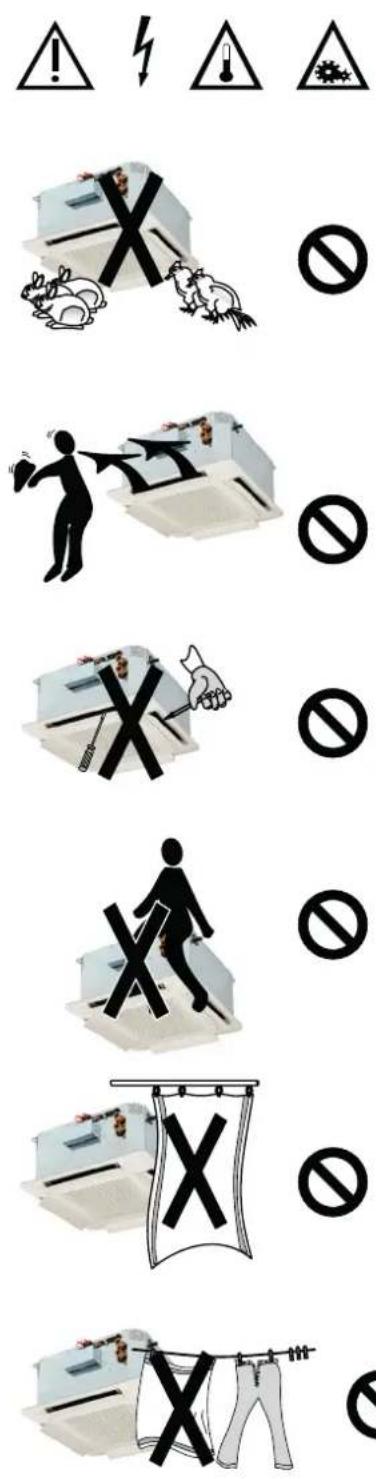
- DO NOT JERK OR TWIST THE POWER CABLE!!
Never pull, step on or crush the power cable, nor secure it with nails or tacks. A damaged cable could cause short circuits or personal harm.
- DO NOT USE THE UNIT IMPROPERLY
The unit should not be used in breeding, birthing or raising animals.
- DIRECT THE AIR JET CORRECTLY
Adjust the fins so that the air flow is not aimed directly at people as this could lead to discomfort.
- DO NOT INSERT OBJECTS INTO THE AIR OUTLET
Never insert objects of any kind into the air outlet slats. This could cause personal injury or damage the unit.
- DO NOT SIT ON THE UNIT
- DO NOT COVER
Do not cover the unit with objects or curtains that could partially obstruct air flow.
- WARNING
When the unit is running, do not place any objects or cloths to dry on the air outlet grille as they would obstruct the air flow and damage the unit.
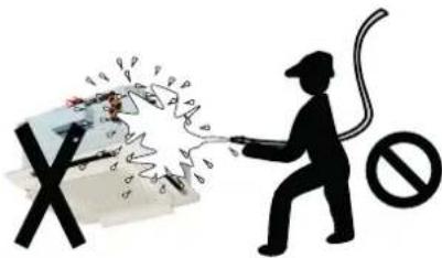
- TO CLEAN THE UNIT:
Do not direct water jets at the unit. It could lead to electric shock or damage the unit. Do no use hot water, abrasive powders or strong solvents; clean the unit with a soft cloth.
RULES FOR THE USER: SHUTDOWN AT THE END OF THE SEASON
- Cut off the power to the unit with the main omnipolar circuit breaker on the power supply line.
- Close the water supply valves.
- If the unit is installed in areas with particularly cold climates, empty the water from the system during long system shutdown periods.
These units are constructed with state-of-the-art technology that ensures long-term efficiency and operation, in addition to a high level of safety in accordance with the regulations in force.
To keep the unit in good working condition and fully safe, it is essential to follow a regular inspection and maintenance schedule (to be assessed on a case-by-case basis).
The following schedule is based on good/standard/normal conditions regarding the pollution/dirt/dust in the air and the installation site (optimal situation). The maintenance intervals are purely indicative and can be reduced (possibly a lot) in relation to the actual working conditions. The most aggressive atmospheric conditions occur when the air contains an abnormal quantity of industrial fumes, salts, chemical fumes, industrial powders, dust, dirt, etc.
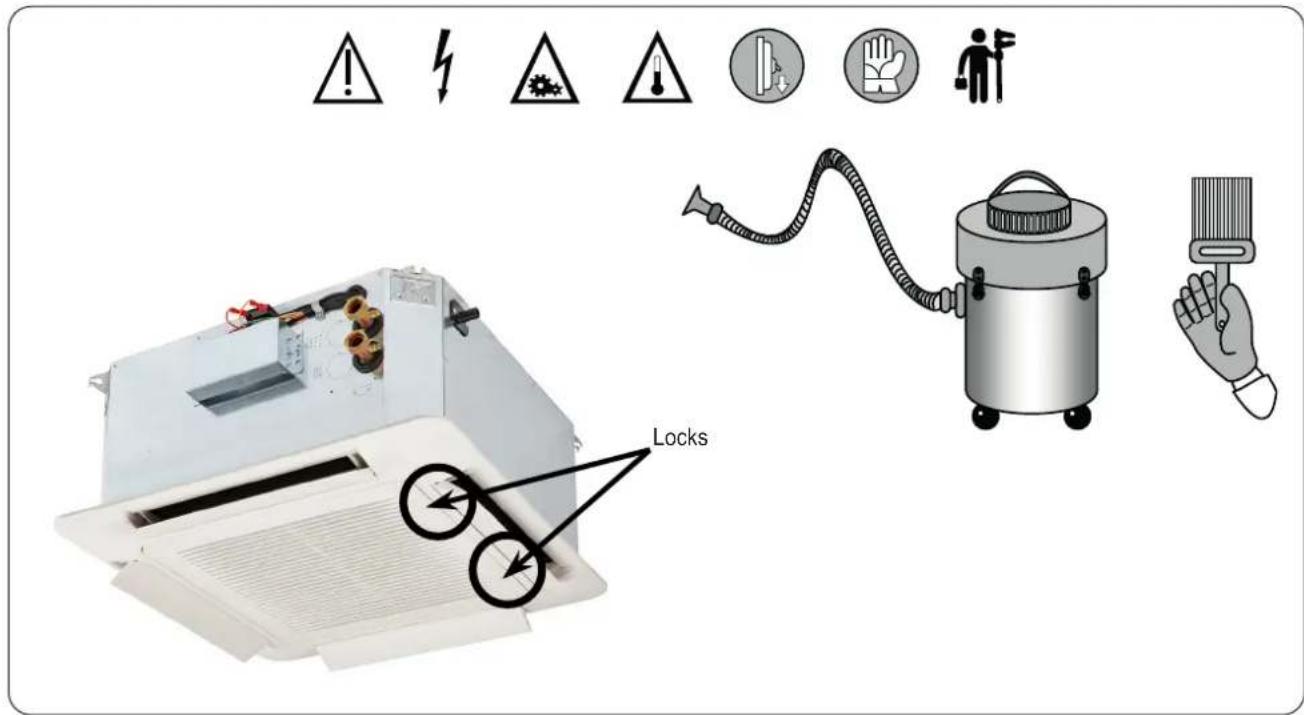
TO CLEAN THE UNIT:
WARNING! Switch off power supply before cleaning unit.
Do not splash water on the unit. It could result in electrical shock or damage to the unit. Do not use hot water, abrasive powders or strong solvents, acid solutions, basic solutions. To clean unit use a soft cloth possibly moistened with water at room temperature. Avoid the working during the cleaning of the rooms.
EN - 16
ROUTINE MAINTENANCE (TO BE CARRIED OUT BY THE USER): MONTHLY CHECKS
- NOTE:
Adequate maintenance ensures safety and savings!
For environments with “normal” levels of cleanliness, it is advisable to carry out the following operations at the beginning of each cooling and heating season, and thereafter at least once every month of operation:
- CLEANING:
Clean the external parts of the unit simply using a damp cloth.
- AIR FILTER:
Clean the ter mat simply by beating it, washing it with water and detergent, or using a jet of compressed air.
IMPORTANT: when cleaning the Alter, make sure that the water/air jet passes through the media in the opposite direction to that of normal operation, and ensure that it is not strong enough to damage the Alter media. If alters are washed with water, dry them in the open air before re-installation in order to avoid compromising system efficiency.
To clean air □ter, follow the procedure below:
- With the help of a ☐at-blade screwdriver rotate of 90° the locks placed on the intake grid of the front panel as shown in previous ☐gure.
- Remove the □iter from the inner rails, being careful not to break.
- Once cleaned, re-insert the Alter into the guide and close the grid by turning the locks of 90° in the opposite way than the opening.
- Always reassemble the □iter after cleaning it before restarting the unit.
- CONDENSATE DRAIN:
During the summer season, check that the condensate drain is not obstructed and that the pan is clean and free of dust or anything else. Any dirt may obstruct the drain, causing the condensate to overflow. If it is dirty, request the intervention of the after-sales service.
ROUTINE MAINTENANCE (TO BE CARRIED OUT BY QUALIFIED PERSONNEL): YEARLY CHECKS
The ensure the unit is kept in good working condition, periodic maintenance is mandatory at least once a year. Remember that maintenance must be carried out by qualified personnel only. The first annual check on the unit is carried out entirely by the qualified maintenance technician, with the related responsibilities.
- CHECKING THE ELECTRICAL PARTS:
Check all electrical equipment, and in particular the tightness of the electrical connections. Check the electrical absorption.
- CHECK THE TIGHTNESS of all nuts, bolts and ranges that may have been loosened by vibrations.
- VIBRATIONS/NOISE:
Check that the unit operates without vibrations or abnormal noise.
- VENTILATION CIRCUIT INLET/OUTLET:
Check that they are not obstructed, which lead to overheating the windings.
- FAN/MOTOR UNIT:
Both the motor and fans rotate on self-lubricating bearings that do not need maintenance. Make sure the impeller is clean. Check that the fan is free of dirt and foreign bodies. If this is not the case, clean it using compressed air, taking care to avoid damaging the impeller.
- MOTOR:
Make sure that there are no traces of dust, dirt or other impurities on the motor. Any dust/dirt entering the moving parts (especially bearings/bushings/etc.) could cause the components to seize/bind, increasing resistance to movement and eventually blocking the system, overheating the motor, or causing burning or damage.
- AIR FILTERS:
In addition to routine cleaning/maintenance to be carried out by the user, replace all the air filters at least once a year or 3,000 hours of operation.
- WATER COIL:
The heat exchanger coil must be kept in perfect condition to guarantee the technical design specifications. Check that the nned wall has no obstructions to airflow; if necessary, clean it and be careful not to damage the aluminium ns. To clean it, use a little brush or a vacuum cleaner, which is even better.
- CONDENSATE DRAIN:
Micro-organisms and mould can flourish in the drain pan, so it is very important to deep clean it at least once a year with suitable detergents, and disinfect it with sanitizing products.
After cleaning, pour water into the drain pan to check that it follows out properly.
For all installation, start-up, etc., always consult professionally qualified personnel.
Before calling the technical service, make sure you have the technical documentation for the unit.
You must give:
- Unit model, product serial no., approximate hours of operation
- Brief description of the installation type + type of fault found
RULES FOR THE USER: SPARE PARTS, REPLACING PARTS
- Whenever components have to be replaced, it is advisable to use only original spare parts and components, otherwise the warranty on the entire unit will be invalidated: For safety and quality reasons, use only original spare parts when replacing components!!
- When ordering spare parts, always give the unit model, product serial no., and description of the part to be ordered.
- Since specific technical skills are required to replace spare parts, always contact specialist technical personnel authorized by the manufacturer.
- WARNING!
All spare part replacement procedures must be carried out with the unit off and the water and electric supplies disconnected.
DISPOSAL
At the end of its operating life, the unit must be disposed according to the regulations in force in the country of installation. Avoid leaks or spills in the environment.

The units are made of the following materials:
- Galvanized sheet steel, pre-painted, stainless steel, aluzink
- Copper, aluminium
- Polyester, polyethylene, glass fibre, plastic, ABS
TROUBLESHOOTING (TO BE CARRIED OUT BY QUALIFIED TECHNICIANS)
- MÁNDATORY:
BEFORE ACCESSING THE UNIT, WEAR SUITABLE PROTECTIVE CLOTHING AND CUT OFF THE POWER SUPPLY TO THE UNIT USING THE OMNIPOLAR CIRCUIT BREAKER.
| FAULT POSSIBLE CAUSES – CHECKS - REMEDIES | |
| LOW AIR OUTFLOW | Wrong speed setting on the control panel: Select the right speed on the control panel. |
| Air filter clogged: Clean the air filter. | |
| Air flow obstruction (inlet and/or outlet): Remove the obstruction. | |
| Sense of rotation reversed: Check the wiring diagram and electrical connections. | |
| AIR FLOW TOO HIGH Rotation speed too high: Reduce the fan speed. | |
| EXCESSIVE NOISE | Air flow too high: Reduce the air flow. |
| Metal components damaged: Check the state of the components and replace damaged parts. | |
| Rotating parts off balance: Balance the fan impeller. | |
EN - 18
| FAULT POSSIBLE CAUSES - CHECKS - REMEDIES | |
| THE MOTOR (FAN) DOES NOT TURN | No power: Check the power supply. |
| The minimum water temperature protection has been activated, if present, because the water has fallen below the minimum temperature set for winter operation. Check the heat generator. | |
| Make sure that:- The power supply is on- The switches and/or thermostats are in the operating position. | |
| Make sure that: No objects are obstructing the fan rotation. | |
| THE UNIT DOES NOT HEAT AS BEFORE | No hot water supply: Check the boiler and the hot water pump. |
| Wrong setting on the control panel: Set the control panel correctly. | |
| Make sure that: The air filter and coil are clean. | |
| Make sure that: No air has entered the water circuit, check it using the air vent valve provided. | |
| Make sure that:- The system is correctly balanced- The boiler is working- The hot water pump is working. | |
| THE UNIT DOES NOT COOL AS BEFORE | No cold water supply: Check the chiller and chilled water pump. |
| Wrong setting on the control panel: Set the control panel correctly. | |
| Make sure that: The air filter and coil are clean. | |
| Make sure that: No air has entered the water circuit, check it using the air vent valve provided. | |
| Make sure that:- The system is correctly balanced- The chiller is working- The cold water pump is working. | |
| WATER LEAKS | Check and improve the insulation of the water pipes |
| Tighten the water connections | |
| Fix the unit perfectly horizontally | |
| Clean the drain pan | |
| Check and clean the pipe of the condensate drain; | |
| Check the proper functioning of the condensate drain pump | |
| Check the slope of the auxiliary drain pan | |
| CONDENSATION ON THE EXTERNAL STRUCTURE OF THE UNIT | Temperature and humidity limit conditions specified in the “Operating limits” section have been reached: Raise the water temperature above the specified minimum limits. |
| Condensate water draining problems: check the drain pan and the drain outlet. | |
| When the desired ambient temperature is reached, the fan stops while the chilled water continues to circulate in the coil: Provide a regulation system that, in addition to stopping the fan when the ambient temperature is reached, also stops the water supply (e.g. with 3-way valve; 2-way valve; pump OFF; chiller OFF; etc.). | |
| FOR OTHER FAULTS, DON'T HESITATE TO CONTACT THE MANUFACTURER IMMEDIATELY. | |
Bi2 CASSETTE
natural_image
Exterior view of a white industrial air conditioner unit with ventilation ducts and control panel (no visible text or symbols)MODE D'INSTALLATION, D'EMPLOI ET D'ENTRETIEN
FR
ACCESSOIRES
natural_image
Illustration of a two-story rectangular pallet with horizontal straps, no text or symbols presentTRANSPORT, RÉCEPTION ET MANUTENTION
Ne pas mouiller
Ne pas piétiner

natural_image
Simple line drawing of a forklift lifting a box, no text or symbols present

natural_image
Silhouette of two figures exchanging a block with the number 25 (no text or symbols beyond the number)TRANSPORT, MANUTENTION, STOCKAGE SUR CHANTIER
natural_image
Technical diagram showing a square component with directional arrows and a 3D view of a mechanical fan or fan assembly (no text or symbols present)FR - 7
Unités 2 tuyaux
Unités 4 tuyaux
- NE PAS TIRER SUR LE CÂBLE ÉLECTRIQUE !!
- POUR NETTOYER L'UNITÉ :
natural_image
Exterior view of a white industrial air conditioner unit with ventilation ducts and control panel (no visible text or symbols)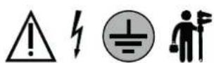
ZUBEHÖR
natural_image
Illustration of a two-story rectangular pallet with horizontal straps and a wooden pallet base (no text or symbols)natural_image
Simple line drawing of a forklift lifting a box, no text or symbols presentnatural_image
Silhouette of two figures exchanging a block with the number 25 (no text or symbols beyond the number)natural_image
Technical diagram showing a square component with directional arrows and a 3D view of a mechanical device with internal components (no text or symbols)Einheit 2 Rohre
Einheit 4 Rohre
INSTALLATION: KONDENSWASSERABLASS
- ZIEHEN SIE NICHT AM STROMKABEL!!!
- UM DAS GERÄT ZU REINIGEN:
(Brushless + Driver/Inversor)

natural_image
Exterior view of a white industrial air conditioner unit with ventilation ducts and control panel (no visible text or symbols)
ACCESORIOS
natural_image
Illustration of a two-story rectangular pallet with horizontal straps and a wooden pallet base (no text or symbols)natural_image
Simple line drawing of a forklift lifting a box (no text or symbols)

natural_image
Silhouette of two figures exchanging a block with the number 25 (no text or symbols beyond the number)natural_image
Technical diagram showing a square component with directional arrows and a 3D view of a mechanical device with internal components (no text or symbols)Unidad 2 tubos

Unidad 4 tubos
- PARA LIMPIAR LA UNIDAD:
natural_image
Exterior view of a white industrial air conditioner unit with ventilation ducts and control panel (no visible text or symbols)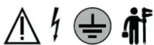
ACESSÓRIOS
natural_image
Illustration of a two-story rectangular pallet on a pallet stand, with no text or symbols present.natural_image
Simple line drawing of a forklift lifting a box, no text or symbols presentnatural_image
Silhouette of two figures exchanging a block with the number 25 (no text or symbols beyond the number)natural_image
Technical diagram showing a square component with directional arrows and a 3D view of a mechanical device with internal components (no text or symbols)Unidade de 4 tubos
- ATENÇÃO
- PARA LIMPAR A UNIDADE:
(Brushless + Driver/Inverter)
natural_image
Exterior view of a white industrial air conditioner unit with ventilation ducts and control panel (no visible text or symbols)HANDLEIDING VOOR DE INSTALLATIE, HET GEBRUIK EN HET ONDERHOUD NL

ACCESSOIRES
natural_image
Illustration of a two-story rectangular pallet with horizontal straps, no text or symbols presentTRANSPORT, ONTVANGST, VERPLAATSING
Niet nat maken
Niet betreden

natural_image
Simple line drawing of a forklift lifting a box (no text or symbols)natural_image
Silhouette of two figures holding a block with the number 25 (no text or symbols on figures)INSTALLATIE: PLAATSING UNIT
- VERPLICHT:
natural_image
Technical diagram showing a square component with directional arrows and a 3D view of a mechanical device with internal components (no text or symbols)INSTALLATIE: TECHNISCHE RUIMTEN VOOR ONDERHOUD

2-pijps unit

4-pijps unit
INSTALLATIE: CONDENSAFVOER
- TREK NIET AAN DE STROOMKABEL!
- OM HET TOESTEL TE REINIGEN:
natural_image
Exterior view of a white industrial air conditioner unit with ventilation ducts and control panel (no visible text or symbols)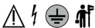

ПАРЕЛКОМЕНА
natural_image
Illustration of a two-story rectangular pallet with horizontal straps, no text or symbols presentnatural_image
Illustration of a forklift lifting a box, with no text or symbols present.natural_image
Silhouette of two figures holding a block with the number 25 (no text or symbols on figures)natural_image
Technical diagram of a mechanical assembly with a bolt and nut, enclosed in a circle (no text or labels)Στερέωση πάνελ:
natural_image
Pure diagram of a square frame with four arrows indicating direction, no text or symbols present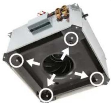
natural_image
Close-up of a mechanical device with arrows indicating rotation or movement around a central fan (no text or symbols visible)Μονάδα 4 σωλήνων
natural_image
Exterior view of a white industrial air conditioner unit with ventilation ducts and control panel (no visible text or symbols)INSTRUKCJA INSTALACJI, OBSŁUGI I KONSERWACJI
PL
AKCESORIA
natural_image
Illustration of a two-story rectangular pallet with horizontal straps, no text or symbols presentnatural_image
Simple line drawing of a forklift lifting a box, no text or symbols presentnatural_image
Two silhouetted figures holding a rectangular block with the number 25, no text or symbols present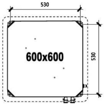

natural_image
Technical diagram of a mechanical assembly with a bolt and nut, enclosed in a circle (no text or labels)Mocowanie panelu:
natural_image
Pure diagram of a square frame with four arrows indicating direction, no text or symbols present
natural_image
Close-up of a mechanical device with arrows indicating directional flow or movement around a central fan (no text or symbols visible)Jednostka 2-rurowa
Jednostka 4-rurowa
- NIE WYKORZYSTYWAĆ JEDNOSTKI W NIEWŁAŚCIWY SPOSÓB
- PRZESTROGA
- CZYSZCZENIE JEDNOSTKI:
- WLOT / WYLOT OBWODU WENTYLACJI:
natural_image
Exterior view of a white industrial air conditioner unit with ventilation ducts and control panel (no visible text or symbols)HANDBOK FÖR INSTALLATION, DRIFT OCH UNDERHÅLL
SV

TILLBEHÖR
natural_image
Illustration of a two-story rectangular pallet with horizontal straps, no text or symbols presentnatural_image
Simple line drawing of a forklift lifting a box, no text or symbols presentnatural_image
Two silhouetted figures holding a large block with the number 25, no text or symbols presentnatural_image
Technical illustration of a device with directional arrows indicating rotation or movement, alongside its exploded view showing internal components (no text or symbols)INSTALLATION: TEKNISKA UTRYMMEN FÖR UNDERHÅLL

INSTALLATION: HYDRAULANSLUTNING
- WARNING:
- DRA INTE I ELKABELN!
- FÖR INTE IN FÖREMÅL I LUFTUTLOPPET
- FÖR RENGÖRING AV AGGREGATET:
natural_image
Exterior view of a white industrial air conditioner unit with ventilation ducts and control panel (no visible text or symbols)TELEPÍTÉSI, HASZNÁLATI ÉS KARBANTARTÁSI KÉZIKÖNYV
HU
TARTOZÉKOK
natural_image
Illustration of a two-story rectangular pallet with horizontal straps, no text or symbols presentnatural_image
Simple line drawing of a forklift lifting a box, no text or symbols present

natural_image
Silhouette of two figures holding a rectangular block with the number 25 (no text or symbols on figures)natural_image
Technical diagram showing a square component with directional arrows and a 3D view of a mechanical device with internal components (no text or symbols)TELEPÍTÉS: KARBANTARTÁSI MUNKATERÜLET