SS-21850 - Fan Sogo - Free user manual and instructions
Find the device manual for free SS-21850 Sogo in PDF.

| Brand | Sogo |
| Model | SS-21850 |
| Product type | Ceiling fan with LED light |
| Power supply | 220-240 V ~ 50 Hz |
| Motor power | 36 W |
| Light power | 40 W (LED) |
| Number of speeds | 6 speeds |
| Remote control | Yes, with pairing function |
| Timer | Yes, adjustable |
| Reversible function | Yes (summer/winter mode) |
| Lighting modes | Warm white, daylight, cool white (CCT) |
| Night mode | Yes, reduced speed and silent |
| Blade diameter | 132 cm (approx.) |
| Weight | Approximately 6 kg (approx.) |
| Minimum floor height | 2.3 m |
| Distance from walls | At least 76 cm |
| Maintenance | Clean with a dry or slightly damp cloth, do not use water |
| Repairability | By a licensed electrician only |
| Spare parts | Balancing kit, remote control, LED bulb, blades |
| Warranty | After-sales service via www.sogosat.com |
| Manufacturer | Sanysan Appliances S.L. (Spain), manufactured in China |
Frequently Asked Questions - SS-21850 Sogo
User questions about SS-21850 Sogo
0 question about this device. Answer the ones you know or ask your own.
Ask a new question about this device
Download the instructions for your Fan in PDF format for free! Find your manual SS-21850 - Sogo and take your electronic device back in hand. On this page are published all the documents necessary for the use of your device. SS-21850 by Sogo.
USER MANUAL SS-21850 Sogo
natural_image
White ceramic spoon with a curved handle and 'SOGO' logo on the lid (no additional text or symbols visible)
Descarga tu manual Download your manual Téléchargez votre manuel Baixe seu manual Laden Sie Ihr Handbuch herunter Scarica il tuo manuale Stáhněte si manuál Download din manual Prenesite svoj priročnik Preuzmite svoj príručnik Pobierz swoją instrukcję Descárcați manualul dvs Завантажте посібник Descàrrega el teu manual
ref. SS-21845
SS-21850
- Ventilador de techo de 42" con aspas retráctiles (bajo consumo)
- 42" Ceiling fan with retractable blades
- Ventilateur de plafond 42 pouces avec pales rétractables
- Ventilador de teto de 42" com pás retráteis
- 42" Deckenventilator mit einziehbaren flügeln
- Ventilatore da soffitto da 42" con palette retrattili
- 42" Stropní ventilátor se zasunu-jícími křídly
• 42" Loftventilator med udtrekkelige blade
• 42" Stropný ventilátor s vysuvateľnými lopatka
- 42" Stropni ventilator s uvlačivim lopatama
- 42" Calowy wentylator sufitowy z chowanymi łopatkami
- Ventilator de tavan de 42" cu pale retractabile
• 42-Дюймовий стельовий вентилятор із висувними лопатями
- Ventilador de sostre de 42" amb pales retràctils
ESPAÑOL....P. 3
ENGLISH P. 11
FRANÇAIS P.19
PORTUGUESE P. 27
DEUTSCH P. 36
ITALIANO P. 45
ČEŠTINA P. 53
DANSK P. 61
SLOVENSKI P. 69
HRVATSKI P. 77
POLSKI P. 85
ROMÂNĂ P. 93
Declaration of conformity, Responsibility of Electronic products disposal, Importers Details and After-sales service on the last pages.
5. INSTRUCCIONES DE MONTAJE


natural_image
Pure technical diagram of a mechanical or electrical component without any text, numbers, or symbolsnatural_image
Mechanical assembly diagram showing a rotating component and a flanged housing (no text or labels)- INSTRUCCIONES DE USO
natural_image
Line drawing of a hand using a tool to adjust or install a mechanical component (no text or symbols present)
IMPORTANT:
• Always read the instruction book carefully before using.
- This manual can be downloaded from our webpage www.sogo.es
- Keep these instructions for future reference.
SAFETY INSTRUCTIONS FOR THE USER

General Precautions:
- Do not use the appliance for any other purpose than described in this manual.
- This product is intended for indoor, non-industrial, non-commercial and only for household use. Do not use the item outdoors or for any other purpose. Misuse or improper handling may cause problems in the appliance and cause injury to the user.
- Ensure that the voltage indicated on the nameplate matches the mains voltage before plugging in the appliance.
- Never use accessories that are not recommended by the manufacturer.
- The use of accessories not recommended or sold by the appliance manufacturer may result in fire, electric shock or injury to persons
- Do not use the appliance if the cable or plug is damaged. In case of the cord be damaged, it must be replaced only by the manufacturer, its service agent or similarly qualified persons in order to avoid Hazard.
- In case of appliance malfunction, or if it has been damaged in any manner, return the appliance to the nearest authorized service facility for examination, repair or adjustment.
- In case of hardware problems, do not attempt to repair the product yourself. Repairs should only be carried out by qualified technicians.
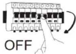
- Turn the fan OFF when not in use and before disassembling or cleaning. Fully assemble the fan before switching on again.
- WARNING: To reduce the risk of personal injury, do not bend the blade brackets (also referred to as "flanges") during assembly or after installation. Do not insert objects in the path of the blades.
- To avoid personal injury or damage to the fan and other items, be cautious when working around or cleaning the fan. Do not use water or detergent when cleaning the fan or fan blades. A dry dust cloth or lightly dampened cloth will be suitable for most cleaning.
-
The appliance is not to be used by persons (including children) with reduced physical, sensory or mental capabilities, or lack of experience and knowledge, unless they have been given supervision or instruction.
-
This appliance can be used by children aged from 8 years and above and persons with reduced physical, sensory or mental capabilities or lack of experience and knowledge if they have been given supervision or instruction concerning use of the appliance in a safe way and understand the hazards involved.
- Children should be supervised to ensure that they do not play with the appliance.
• Cleaning and user maintenance shall not be made by children. - Keep the appliance and its cord out of reach of children less than 8 years.
- Do not allow the children to use the appliance without supervision.
• Children shall not play with the appliance.

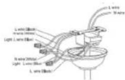
Installation Instructions
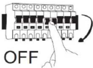
Please remove the fuse or turn off the circuit breaker to cut off the power before installing the fan. Ensure all electrical connections are in compliance with local laws, regulations and national electrical codes. If you are not familiar with electrical installation and wiring, please hire a qualified electrician or consult the wiring manual.
- For your safety, all electrical connections and disconnections should be performed by a qualified electrician.
- Any action performed for the electrical connection of the device must be carried out after ensuring that the general power supply is disconnected, by removing the corresponding fuse or disarming the protective switch in order to ensure total isolation of the power supply.
- When deciding where to mount the fan, be sure that there is at least 30 inches (76 cm) of space between the fan and any wall or other obstruction that the fan blades could collide with. The greater this distance, the more effective the air flow produced. After the fan is mounted, be sure that the blades are no less than 7.8 ft (2.3 m) above the ground.
- The anchor point for the fan must be able to support a weight of at least 100 pounds (45 kg). If mounting on a ceiling junction box, be sure that the fan is adequately supported to prevent loosening or turning.
- The fan's electrical connection must be "grounded" (the fan's ground cable connected to the installation's grounding network) in order to avoid any branching that may be dangerous to people.
- Do not connect the fan's power supply to any dimmers, potentiometers, or light switches, as it will cause the fan to malfunction and/or will damage the motor. The fan must be directly connected to a properly protected installation circuit
(magneto thermal differential switch with the adequate size for the fan's consumption and technical specifications). Only use the fan's control to turn it on or stop it.
- It is recommended to not use these types of fans along with gas installations simultaneously in the same room.
- The fan must not be moving at all and must have come to a complete stop before changing its direction of rotation. This will prevent damage to its motor and to the control unit, when applicable.
- Do not insert anything that could hit the fan's blades into its pathway while it is moving, as this could cause damage to people, can damage the blades, and can offset the balance of the unit, causing vibrations and wobbling.
- After installing the fan, ensure that all fastenings are secure and tightened in order to avoid any noise caused by loose elements.
- Due to the fan's movement, certain fastenings may become loose. Check all fastenings twice per year at a minimum in order to ensure that they are sufficiently tight. If necessary, they must be retightened.
- The motor housing can be cleaned with a soft brush or a lint-free cloth to avoid scratching the surface. Clean the blades with a lint-free cloth. Important: Turn off the main power supply before starting any maintenance. Do not clean the fans with water or a damp cloth.
- WARNING: If unusual oscillating movement is observed, immediately stop using the ceiling fan and contact the manufacturer, its service agent or suitably qualified persons.
- That the replacement of parts of the safety suspension system device shall be performed by the manufacturer, its service agent or suitably qualified persons.
- Stationary appliances not fitted with means for disconnection from the supply mains having a contact separation in all poles that provide full disconnection under overvoltage category III, the instructions state that means for disconnection must be incorporated in the fixed wiring in accordance with the wiring rules.
- The fixing means for attachment to the ceiling such as hooks or other devices shall be fixed with a sufficient strength to withstand 4 times the weight of the ceiling fan.
- That the mounting of the suspension system shall be performed by the manufacturer, its service agent or suitably qualified persons;
- Check to make sure that all motor housing screws are snug.
- Check to make sure that the screws which attached the fan blade holder to the motor are tight.
- Check to make sure wire nut connectors in switch housing are
not rattling each other.
- Make sure to turn off the main power, before entering swich housing
- Do not use a sold state variable speed control.
- It is possible that your fan emits some kind of noise initially. Most noises are related to the new fans, which will disappear soon.
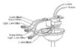
- If light doesn't work, make sure wire is connected to main housing. Check for loose or disconnected wires in fan switch housing. Check for loose or disconnected wires in light kit. Check for faulty LED lights.
Note: The important warnings and instructions indicated in this manual are not guaranteed to cover all possible conditions and situations that may occur. It must be understood that common sense, precaution, and care are factors that cannot be included in all products. These factors can and must only be provided by the user who maintains and enjoys this fan.
- TECHNICAL SPECIFICATIONS
| Voltage Frequency | Fan Power Light power | |
| CA 220-240 V 50 Hz | 36W 40W |
This product complies with EU regulation 2023/826 under directive 2009/125 EC on the Eco design requirements.
Power consumption in off mode:
Power consumption in standby mode:
Time after which the product enters into off mode:
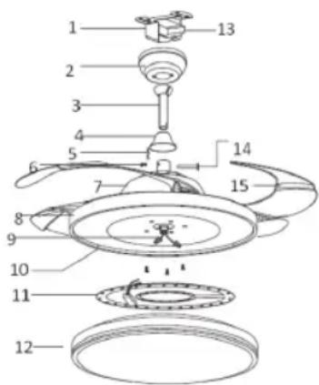
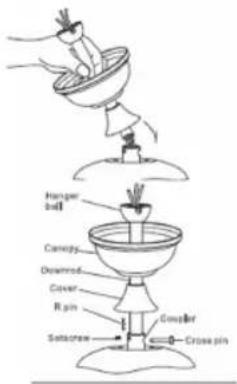
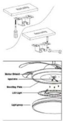
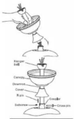
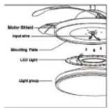
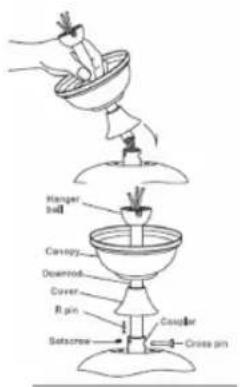
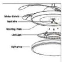
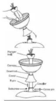
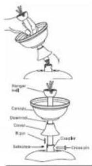
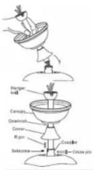
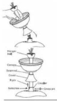
4. PARTS DESCRIPTION
- Hanging bracket
- Upper canopy
- Down rod
- Lower canopy
- Snap pin
- Screw
- Upper shield
- Motor shield
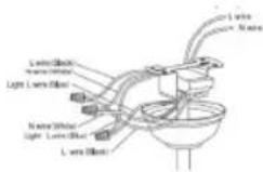
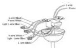
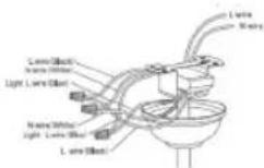
- Input wire
- Mounting plate
- LED light
- Light cover
- Remote control receiver
- Hex nut
- Blades
- Remote control (Batteries not included)
- Blade balancing kit (When apply)
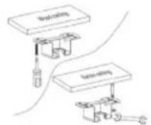
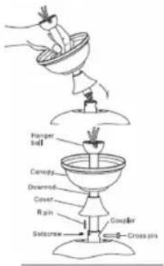
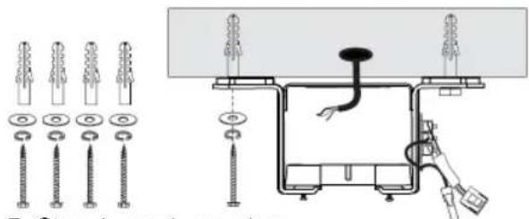
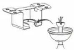
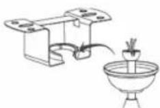
5. ASSEMBLY INSTRUCTIONS
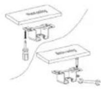
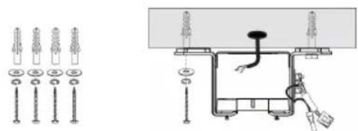
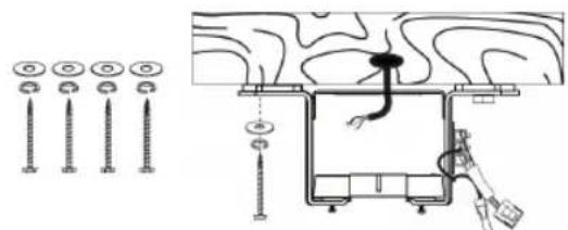
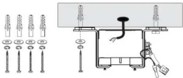
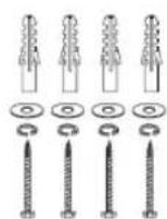
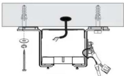
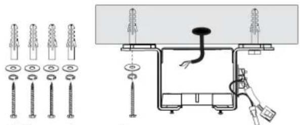
A- Installing hanger bracket: Secure the hanger bracket to the ceiling joist or adequate piece of timber inserted between ceiling joists. The bracket should be attached with long screws supplied.
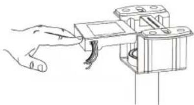
B. Remove the screws from motor shield. Remove the mounting platform and light group. Assemble the mounting plate And motor shield with screws and assemble the light group.
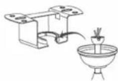
C. Remove the R Pin and cross pin from the down rod. Thread the wires through down rod and insert the down rod into the couple.
D. Loose 2 set of screws in the down rod support. Install the cross pin and secure with R-pin.
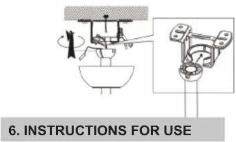
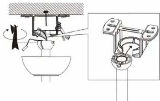
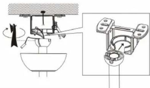
E- Carefully hang the fan assembly into hanger bracket, which is attached to outlet box. Make sure that the groove in the ball is lined up with tab on the hanger bracket.
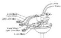
F. After wiring, attached the canopy to the hanger bracket by pushing up and twisting to the locate screws in key holes then tighten up the screws.


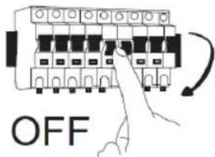
(1) Note: Turn off the fan power supply at the circuit breaker box and wall switch.
Note: Failure to disconnect the power supply, prior to installation, might result in serious injury or death.
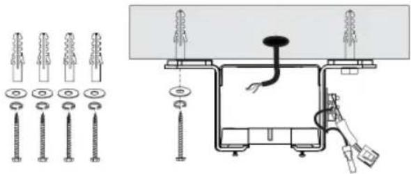
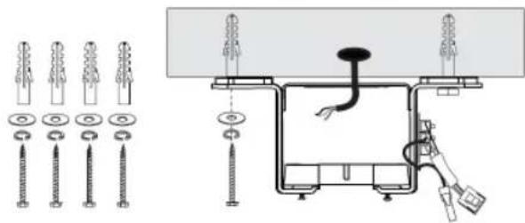
(2) If it is cement ceiling, please drill the installation hole at the installation location.
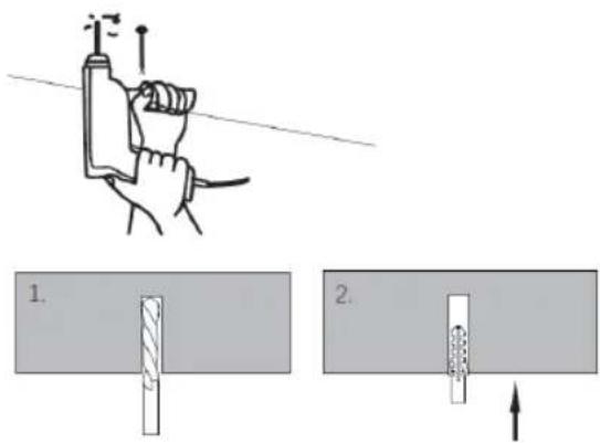
(3) Snap assembled fan into the installed bracket
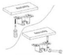
A. Cement ceiling
natural_image
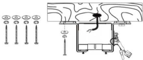
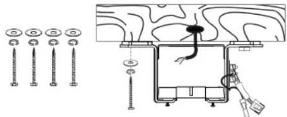
Technical diagram showing installation of screw fasteners and electrical insulator components (no text or labels)B. Solid wood ceiling
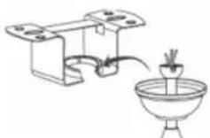
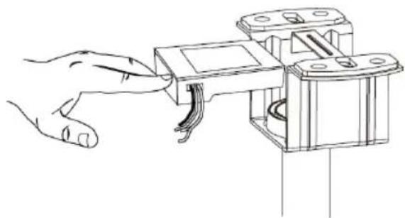
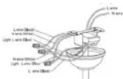
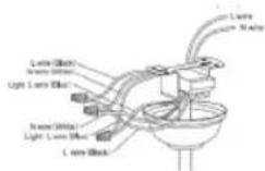
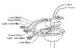
(4) Put the receiver into the bracket and arrange the wires.
REMOTE CONTROL OPERATIONS
-
Insert the batteries into the remote control.
-
Light On/Off: to turn on and off the light
- Fan speeds: to select fans speeds from 1-6
- Fan off: to turn off the fan
- Light modes with warm white, day light and cool white
- Light intensity button: with this button light intensity can be changed.
- Timer: to select the timer accordingly
- Off button
- Reverse and forward fan function
- Normal and sleep mode
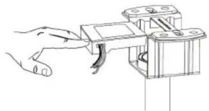
natural_image
Line drawing of a hand interacting with a mechanical component (no text or symbols)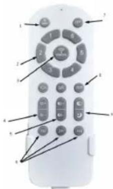
Pairing of remote control with the receiver:
- Press and hold Fan/Off button within 5 seconds of power on and remote-control indicator light flashes to complete pairing.
- To unpair, press and hold Fan/Off button within 3 seconds of power on and remote-control indicator light flashes to complete unpairing.
• Note: Receiver should not be installed upside down to not to affect the unevenness of ceiling - Receiver is divided into input and output, make sure to connect correct wiring.
• Wall switch must be power on to control effectively.
Warm white: Press and hold button 4 to change light temperature "3000K"
Note: If the actual light colour is cool light, then by pressing this button colour temperature will change slowly from cool light to warm light.
Cool white: Press and hold to change light temperature "6500K"
Note: If the actual light colour is warm light, then by pressing this button colour temperature will change slowly from warm light to cool light.
Day light: Press and hold button 4 to change light temperature "3000-6500K"
Note: If the actual light colour is cool light, then by pressing this button colour temperature will change slowly from cool light to warm light.
LIGHT FUNCTION
This unit works with CCT light function system, which allows us to choose light type as per our need.
There are 3 colours of light type in this function.
- WW: Cool white light
- NW: Day light or normal light
- DW: Warm white light
In order to choose the type of light press the corresponding button and select the light as per need and desire.
FAN WORKING MODES
This fan works with 2 working modes:
Normal Wind mode: In this normal wind mode fan operate normally and with 6 speeds.
Sleep wind mode: In this mode fan operate at a lower speed compared to its regular settings. This reduced speed generates less noise and making it suitable for use during sleep or quiet hours.
REVERSIBLE FUNCTION
Reversible fan is a type of fan that has the capability to change the direction of airflow. This means it can either push air forward or pull air backward, depending on the desired mode of operation.
Below has been explained mechanism of reverse function.
-
Forward mode: In this mode, the fan operates like a traditional fan, pushing air forward. This is the mode that we use during hot weather to circulate air and create a cooling effect. The blades of the fan rotate in a specific direction, usually anticlockwise, to push air forward.
-
Reverse mode: In reverse mode, the fan reverses the direction of airflow, pulling air backward. This mode is often used during colder weather to help distribute warm air more evenly throughout a room. The blades of the fan rotate in the opposite direction, usually clockwise, to pull air backward.
The ability to switch between forward and reverse modes makes reversible fans versatile and suitable for use in various seasons and weather conditions. It allows for better control over airflow and temperature regulation within a space. These fans are commonly found in ceiling fans, window fans, and some portable fans, offering flexibility and convenience to users
DYNAMIC BLADE BALANCING KIT (TO USE WHEN APPLIES)
How to rectify such problems:
- Ensure that all blades are firmly secured to the blade brackets.
- Ensure that all blades are firmly secured to the fan body and that the pitch of the blades are all same.
- From bottom of the fan, inspect the blades visually and ensure None of them are bent or out of line. If you notice a blade is not in the right position or pitch, gently bend the blade holder to the correct position.
- If the fan is still unstable, the tracking of the blades must be checked using a measurement tape, measure the distance from the leading edge of the blade to the ceiling. Ensure this is the same for all blades and if necessary, make small adjustments by gently bending the blade.
If by following all the above steps your fan is still unstable, then the dynamic blade balancing kit must be used.
- Turn the fan on and adjust to the highest speed setting
- Turn the fan off, select a blade and place the balancing clip on to it, halfway between the tip of the blade and the end of the blade.
- Turn the fan on and observe if the wobble has improved.
- Repeat this step on all of the blades and make a note which blade boasted the greatest improvement.
- Place the clip back onto this blade & move up and down on to the length of the blade until you have found a spot that reduces the wobble.
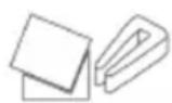
• Install a balancing weight in this spot, ensuring you place the weight on the top face of the blade along the centre line. You may need to use a sharp knife to separate the weights. - Turn the fan on and check that it is now stable & operates fine.
7. CLEANING AND MAINTENANCE
Cleaning:
- Before cleaning, turn the unit off, cut off the power supply from electrical outlet and wait for the unit to cool down.
- To clean the unit, use a soft cloth to wipe off any dust.
- Do not try to open the unit without a licensed electrician. Improperly installed the unit can be dangerous.
- Clean the unit at least once a year.
Maintenance:
- Have your product repaired by a licensed electrician
- This electric product is in accordance with the relevant safety requirements. Repairs should only be carried out by licensed electricians using original spare parts, otherwise this may result in considerable danger to the user.
- Please contact the store which you bought the product for after sale services if any.
TROUBLESHOOTING
| Fan does not work 1. Check all fuses or circuit breakers, if something disrupting the power supply to the fan.2. Turn off electrical power and check all wire connections to fan and in switch housing. It must be carried out by a electrician. |
| Fan turns but airflow is inadequate1.The fan may be running in reverse, so air is going upward.2.The room may contain items that obstruct the air flow.3.The fan may be too small for size of the room. |
| Fan is noisy1.Make sure that the screws fastening blade arm to motor are tight and the lock washers provided for that purpose have been used.2.Lower the upper canopy to ensure a separation from the ceiling of no less than 3mm to reduce Noise.3.Check to see if any of the blades are cracked. If yes, replace all of the blades.4.If this is the first use, leave the fan on for at least 8 hours. If the mechanical noise continues after this period, contact certified electrician. |
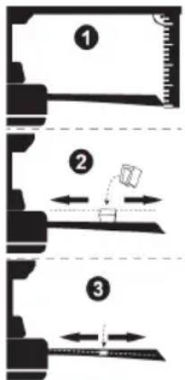
Balancing – Wobbling problems during fan operation
If the fan body wobbles during its operation, this is not a sign of malfunctioning (even if it wobbles a few centimetres). To reduce wobbling, you can turn off the fan, and:
-
Check that all blades are properly fastened by tightening their screws.
-
Check the distance between each blade and the ceiling. Measurements to the ceiling can be carried out as shown in the following diagram. If variations exist and you have already correctly tightened the screws, check that all blades have the same shape. If any of them have a shape that is visibly different, this may be causing an imbalance during fan operation. If you have completed the previous steps and the wobbling has not resolved, you should apply dynamic balancing with the kit provided, as explained below:
-
Turn the fan to the highest speed to generate the maximum amount of oscillation.
-
Turn off the fan. Choose a random position of the leaf shelf plate (see picture) and put down the balance weight.
-
Turn on the fan and check whether the swing has improved or worsened. Close it again, if the swing does not improve, please adjust the position of the balance weight. Repeat this process and determine the best position to reduce swing.
-
Tear off the double-sided tape of the weighing block and stick it to the final position.

IMPORTANT:
5. INSTRUCTIONS DE MONTAGE


natural_image
Simple line drawing of a heating setup with a box, bulb, and stirrer (no text or symbols)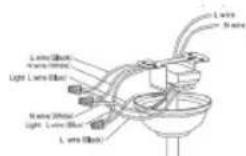
natural_image
Technical line drawing of a ceiling fixture with pipes and fixtures (no text or symbols)natural_image
Diagram of a mechanical or electrical component with no visible text, numbers, or symbols6. MODE D'EMPLOI
natural_image
Line drawing of a hand interacting with a handheld device (no text or symbols)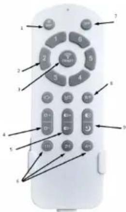

IMPORTANTE:
natural_image
Hand holding a tool with a magnified view of the tip (no text or symbols visible)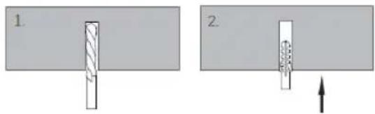
A. Teto de cimento
B. Teto de madeira maciça
(3) Encaixe a ventoinha montada no suporte instalado
natural_image
Technical diagram of a mechanical assembly with no visible text or symbols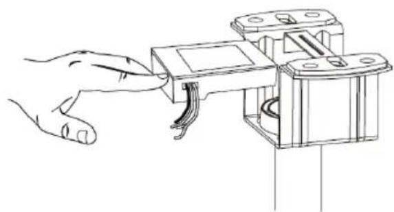
natural_image
Line drawing of a hand inserting a component into a mechanical housing (no text or symbols)
WICHTIG:

A. Zementdecke
B. Massivholzdecke

natural_image
Technical diagram of a mechanical assembly with no visible text or symbols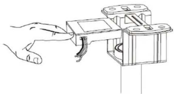
natural_image
Line drawing of a hand inserting a component into a device (no text or symbols)
IMPORTANTE:

natural_image
Mechanical assembly diagram showing a lever mechanism with rotating components and a close-up view of the internal components (no text or labels)- ISTRUZIONI PER L'USO
natural_image
Technical diagram showing mechanical assembly with shafts and housing (no text or labels)natural_image
Line drawing of a hand interacting with a mechanical component (no text or symbols)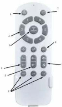

DŮLEŽITÉ
5. MONTÁŽNÍ POKYNY

natural_image
Technical diagram of a mechanical assembly with no visible text or symbols6. NÁVOD K POUŽITÍ
natural_image
Line drawing of a hand interacting with a mechanical device (no text or symbols)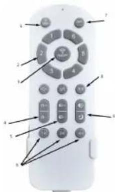

VIGTIGT:
5. MONTERINGSVEJLEDNING
A. Cementloft
natural_image
Technical diagram of a mechanical assembly with no visible text or symbolsnatural_image
Mechanical assembly diagram showing a rotating component and its cross-sectional view (no text or labels)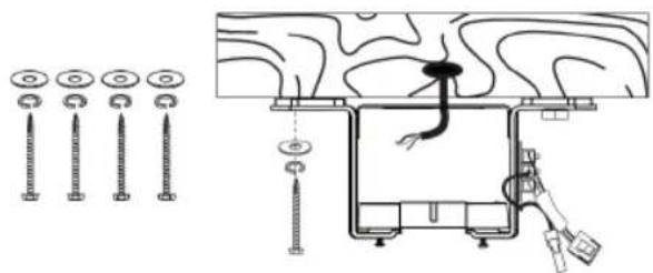
natural_image
Line drawing of a hand connecting a component to a mechanical bracket (no text or symbols)6. BRUGSANVISNING
FJERNBETJENING

POMEMBNO:
5. NAVODILA ZA MONTAŽO


(3) Sestavljeni ventilator zataknite v nameščeni nosilec
A. Cementni strop
(4) Vstavite sprejemnik v nosilec in uredite žice.
natural_image
Technical diagram of a mechanical assembly with no visible text or symbols- NAVODILA ZA UPORABO
UPORABA DALJINSKEGA UPRAVLJALNIKA Vstavite baterije v daljinski upravljalnik.
natural_image
Line drawing of a hand inserting a component into a mechanical housing (no text or symbols)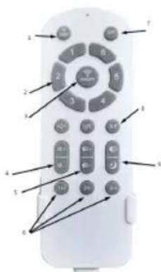
5. UPUTE ZA MONTAŽU
A- Postavljanje zakačnog nosača: Pričvrstite zakačni nosač na gredicu stropa ili na odgovarajući komad drva umetnut između gredica stropa. Nosač treba pričvrstiti dugim priloženim vijcima.
B. Uklonite vijke s zaštitne ploče motora. Uklonite montažnu platformu i grupu svjetala. Složite montažnu ploču i zaštitnu ploču motora pomoću vijaka te složite grupu svjetala.
C. Izvadite R-iglu i križnu iglu iz spuštene šipke. Provedite žice kroz spuštenu šipku i umetnite spuštenu šipku u spojku.
D. Otpustite dva para vijaka na nosaču vodilice. Umetnite poprečni čep i osigurajte ga iglicom.
E- Pažljivo objesite sklop ventilatora na nosač, koji je pričvršćen na razvodnu kutiju. Provjerite je li utor na kugli poravnat s jezičcem na nosaču.
F. Nakon ožičenja, pričvrstite kapu na vješalicu povlačenjem prema gore i zavrtanjem dok se ne poravnaju šarafi u utorima, a zatim ih dobro zategnite.

(1) Napomena: Isključite napajanje ventilatora na razvodnoj ploči i na zidnoj utičnici.
Napomena: Ako ne odspojite napajanje prije instalacije, to može dovesti do ozbiljnih ozljeda ili smrti.
(3) Ugurajte sklopljeni ventilator u instalirani nosač
A. Cementni strop
(4) Stavite prijemnik u nosač i rasporedite žice.
natural_image
Mechanical assembly diagram showing a rotating component and its cross-sectional view (no text or labels)- UPUTE ZA KORIŠTENJE
natural_image
Line drawing of a hand inserting a component into a device (no text or symbols)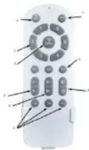
RAD POMOĆU DALJINSKOG UPRAVLJAČA Umetnite baterije u daljinski upravljač.

WAŻNE:
5. INSTRUKCJA MONTAŻU

natural_image
Diagram of a mechanical device with a rotating arm and base, shown in two views (no text or symbols)6. INSTRUKCJE UŻYTKOWANIA
OBSŁUGA PILOTA Włóż baterie do pilota.
natural_image
Technical diagram of a ceiling fixture with pipes and fixtures (no text or labels)natural_image
Pure technical diagram of a mechanical or electrical component with no visible text, numbers, or symbolsnatural_image
Hand using a tool to adjust or install a mechanical component (no text or symbols visible)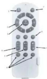
TRYBY PRACY WENTYLATORA

IMPORTANT
5. INSTRUCTIUNI DE ASAMBLARE
natural_image
Technical diagram of a mechanical assembly with no visible text or symbols6. INSTRUCTIUNI DE UTILIZARE
natural_image
Line drawing of a hand inserting or adjusting a component into a device (no text or symbols)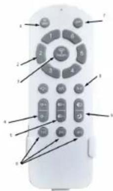

ВАЖЛИВО

natural_image
Mechanical assembly diagram showing a valve mechanism and its internal components (no text or labels)natural_image
Line drawing of a hand inserting a component into a mechanical housing (no text or symbols)
IMPORTANT:
5. INSTRUCCIONS DE MUNTATGE

natural_image
Technical diagram of a mechanical assembly with no visible text or symbols6. INSTRUCCIONS D'ÚS
A. Sostre de ciment
B. Sostre de fusta massissa
natural_image
Line drawing of a hand inserting a component into a circuit board (no text or symbols)EN / ES / FR
Directive 2009/125/EC
| Description Symbol Value Unit | |||
| Power Supply / Fuente de alimentacion / Alimentation 220-240V~ 50Hz | |||
| Power / Potencia / Puissance 36W | |||
| Class / Clase / Classe I | |||
| Maximum fan flow rate / Velocidad máxima de flujo del ventilador / Débit du ventilateur | F m3/min | ||
| Fan power input / Entrada de energía del ventilador / Puissance d'entrée du ventilateur | P W | ||
| Service value / Valor del servicio / Valeur du service SV (m3/min)/W | |||
| Standby power consumption / Consumo de energía en espera / Consommation électrique en veille | P_SB | W | |
| Off power consumption / Consumo de energía apagado / Hors consommation d'énergie | P_off | W | |
| Fan sound power level / Nivel de potencia del sonido del ventilador / Niveau de puissance acoustique du ventilateur | L WA dB(A) | ||
| Maximum air velocity / Velocidad máxima del aire / Vitesse de l'air c meters/sec | |||
| Seasonal electricity consumption / Consumo de electricidad en uso / Consommation d'électricité utilisée | Q kWh/a | ||
| Measurement standard for service value / Estándar de medición para volar del servicio / Norme de mesure pour voler du service | IEC 60879:1986 /corr.1992) | ||
DÉCLARATION DE CONFORMITÉ
DECLARATION OF CONFORMITY
This device complies with EU Low Voltage Directive 2014/35/EC.
Electromagnetic Compatibility Directive 2014/30/EU. Directive 2015/863/EU on the restriction of the use of certain hazardous substances in electrical.
Directive 2009/125/EC on the eco-design requirements applicable to energy-related products.
This symbol on the product or on the packaging indicates that this product can't be disposed as normal rubbish or household waste. All the electrical, electronic equipment's and battery-operated units must recycle in proper manner and according to the local municipal laws. You can recycle them by taking them to government authorized disposal centres or specialized bins which you can find in any nearby big super markets, electronics or electro domestics products stores or malls who have these types of facilities available.
Designed by: SOGO based on European quality standards
Imported by: Sanysan Appliances S.L, NIF: B98753056, C/ Barcas 2, 2, 46002 Valencia, Spain
Product manufactured in CHINA. After-sales service: www.sogosat.com sogosat@sogosat.com / 0034 902 222 161