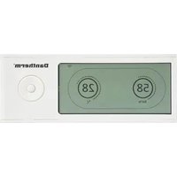
DRC 1 - Air-conditioner Dantherm - Free user manual and instructions
Find the device manual for free DRC 1 Dantherm in PDF.


| Product type | Wireless remote control for Dantherm dehumidifier (CDP/CDP-T/CDF 40-50-70 series) |
| Brand | Dantherm |
| Model | DRC 1 |
| Display | LCD screen with humidity (0–99% RH) and temperature (0–40 °C) scales |
| Power supply | 2 AAA batteries (not included), or USB for firmware update |
| Wireless range | Up to 50 meters (depending on conditions) |
| Main functions | Dehumidification control, heating, extraction fan; alarm display; remote lock |
| User settings | Humidity and temperature set points |
| Installer settings | Extraction fan set point, maintenance interval (1–99 weeks) |
| Alarms | Sensor malfunction, low/high pressure, maintenance, ambient conditions out of limits |
| Pairing | Wireless with the dehumidifier unit (procedure described in the manual) |
| Lock | Switch in battery compartment to disable buttons |
| Navigation | Up/Down, Left/Right, Enter buttons |
| Maintenance | Battery replacement; reset possible by long press (10 s) on left button |
| Dimensions (approximate) | Approximately 12 x 8 x 2 cm (without holder) |
| Weight (approx.) | Approximately 150 g (with batteries) |
| Operating temperature | 0–40 °C |
| Operating humidity | 0–99% RH |
| Compatibility | Dantherm dehumidifiers CDP, CDP-T, CDF 40, 50, 70 |
| Firmware update | Via USB cable (micro-USB) |
| Warranty | Consult the manual or dealer |
Frequently Asked Questions - DRC 1 Dantherm
User questions about DRC 1 Dantherm
0 question about this device. Answer the ones you know or ask your own.
Ask a new question about this device
Download the instructions for your Air-conditioner in PDF format for free! Find your manual DRC 1 - Dantherm and take your electronic device back in hand. On this page are published all the documents necessary for the use of your device. DRC 1 by Dantherm.
USER MANUAL DRC 1 Dantherm
Wireless Remote Controller DRC1 for
CDP/CDP-T/CDF 40-50-70
Languages
en Wireless Remote Controller DRC1 (en) 4
de Kabellose Fernbedienung DRC1 (de)....13
fr Commande à distance sans fil DRC1 (fr)....22
it Comando a distanza senza fili DRC1 (it)....31
es Controlador remoto inalámbrico DRC1 (es) 40
pt Controlador remoto sem fios DRC1 (pt) 49
da Trådløs fjernbetjening DRC1 (da) 58
ru Беспроводная панель дистанционного управления DRC1 (ru) 67
pl Bezprzewodowy pilot sterowania DRC1 (pl)....76
nl Draadloze afstandsbediening DRC1 (nl)....85
Wireless Remote Controller DRC1 (en)
Table of contents
Overview 5
Mating 6
General information....7
User menu - Set points 8
Installer menu....9
Alarms....10
Overview
Warning
It is the responsibility of the operator to read and understand this service manual and other information provided and to use the correct operating procedure.
Read the entire manual before using the control panel. It is important to know the correct operating procedures for the unit and all safety precautions to prevent the possibility of property damage and/or personal injury.
Product description
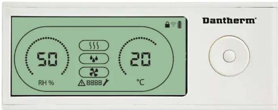
The DRC1 is a wireless remote control panel for use with Dantherm dehumidifier range CDP/CDP-T/CDF 40-50-70.
In this manual you will learn how to use the DRC1 remote control panel to control your dehumidifier.
The range of DRC1 is up to 50 meters depending on conditions.
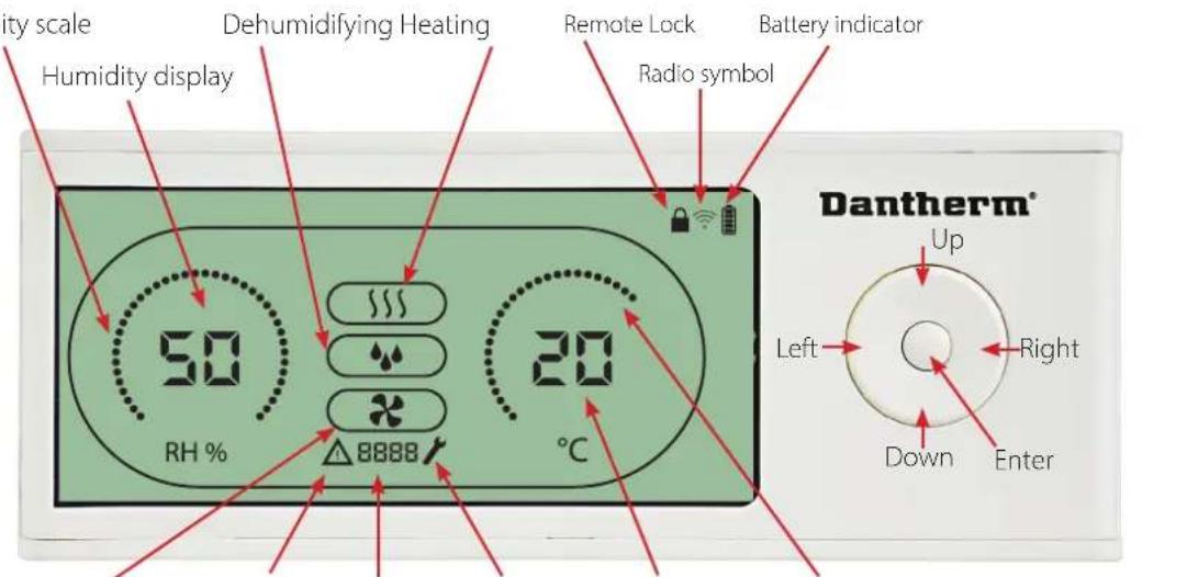
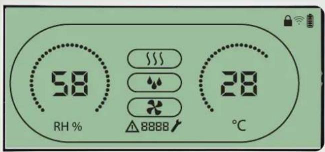
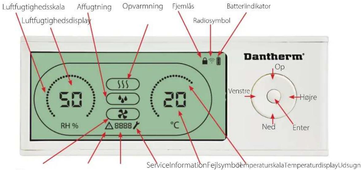
Remote panel Layout Humidity scale
extractor Fan ServiceInformationFail Symbol
Temperature scale Temperature display
Humidity and Temperature scale.
Temperature scale from 0° till 40°C.
Humidity scale from 0 to 99 % RH
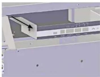
Antennae
natural_image
3D mechanical assembly diagram showing internal components and a highlighted section (no text or symbols visible)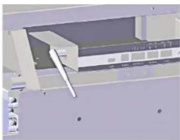
natural_image
3D mechanical assembly diagram showing internal components and mounting holes (no text or symbols visible)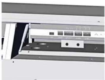
natural_image
Exterior view of a mechanical device with no visible text or symbolsUSB cable The USB cable is for updating software.
It can also be used as external power supply.
Mating
Mating Mode
Before use, the DRC1 must be mated with the CDP unit.
This section describes how to mate the DRC1 with the dehumidifier.
Mating
Dantherm®
Procedure
- Insert batteries > Display flashes (if it does not flash, press the left button for 10 seconds and wait until the display starts to flash)
The DRC1 will search for the dehumidifier for 2 minutes, during which time mating can be done:
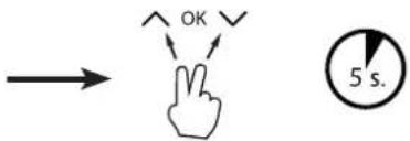
- Press the up and down buttons on the CDP at the same time for 5 seconds
Note: this must be done while the DRC1 is searching for the dehumidifier.

If this procedure does not work:
Switch off the dehumidifier and wait for 5 seconds and then switch it on again.
- The dehumidifier will send a serial number to the DRC1.
When mating is successful, the radio icon comes on.
- The dehumidifier will confirm connection by showing code "Conn" LUN for 3 seconds
More than one remote control panel can be connected to the dehumidifier.
Navigation
End point
End point
ENTER press and hold for 3 seconds to enter user menu setup
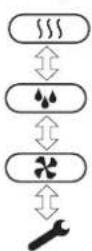
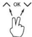
UP and DOWN buttons to navigate between icons.
LEFT and RIGHT buttons allows to change set points value 1 press = 1 unit
ENTER confirms new set point value and automatically switches to next icon/or exits the menu
Press and hold RIGHT for 5 seconds to enter installer menu setup. (Exit setup menu first)
When no button is pressed for 10 sec, the DRC1 exits the menu and returns to readings screen
Failed mating

Press and hold for 10 seconds to reset the serial number stored in DRC1.
If mating fails △ and □□□□ is shown in the display and the radio symbol flashes.
Reset DRC1 and repeat mating process.
Standard readings
Standard readings when connected:
-Stand by, RH and °C scale
-Compressor active, dehumidifying symbol on

General information
Operation

Press and hold for 10 seconds to reset the serial number stored in DRC1.

Press and Hold for 3 seconds to enter user menu setup.

Press and hold for 5 seconds to enter installer menu.
Dantherm®
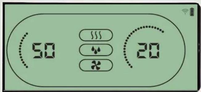
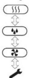
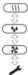
When the dehumidifier is running the dehumidifying symbol ( ♦♦ ) is shown in the DRC1 display.
When heating is toggled ON, the heating icon (\\\$) will be shown in the DRC1 display. When the extractor fan is turned on, the extractor fan icon (✗) will be shown in the DRC1 display.
Fail Condition
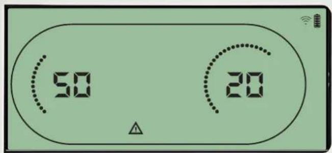
Dantherm®
If the dehumidifier enters fail mode, the warning sign ( ) will be shown in the DRC1 display.
Locked remote
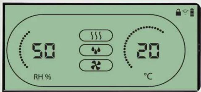
Dantherm®
The DRC1 is equipped with switch in the battery compartment.
When switched to "lock" position, the buttons on the DRC1 become inactive.
The display will still update with information, but does not allow user inputs.
User menu - Set points
Dehumidifying set point

Press for 3 sec to enter user menu setup. Press to confirm.

Decrease with 1 unit

Increase with 1 unit

Navigation between icons

Navigation between icons
Dantherm®
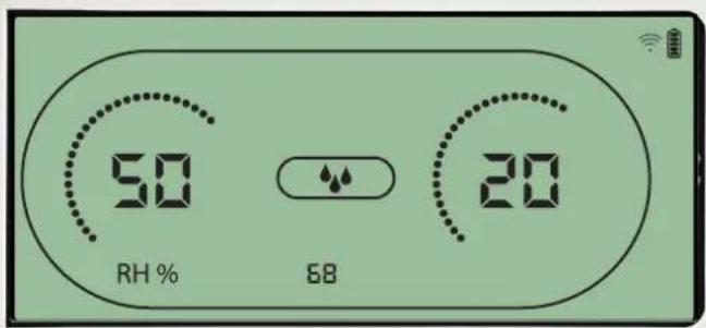
The humidity value and the dehumidifying icon will flash.
The display shows the desired humidity set point.
While flashing, the value can be increased or decreased by pressing Up/Increase or Down/Decrease button on DRC1.
Press enter to confirm humidity set point and go to next menu page.
Temperature set point

Press for 3 sec to enter user menu setup. Press to confirm.

Decrease with 1 unit

Increase with 1 unit

Navigation between icons

Navigation between icons
Dantherm®
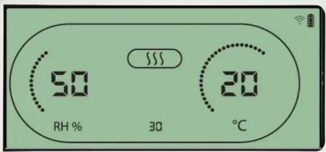
The temperature value and the heating icon will flash.
The value displayed shows the desired temperature set point. While flashing, the value can be increased or decreased by pressing Up/Increase or Down/Decrease button on the DRC1 Maximum: 34 °C, Minimum: 5 °C. Press enter to confirm new set point and go to next menu page.
Installer menu
Press and hold for 5 seconds to enter installer menu.
Fan set point.

Decrease with 1 unit

Increase with 1 unit

Navigation between icons

Navigation between icons

Press to confirm.

Dantherm®
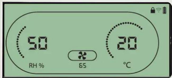
When the extractor fan icon flashes at 0.5 Hz and extractor fan set point value is shown on info line.
Left or right button to decrease or increase value. Enter to confirm set point and go to next icon.
If you do not confirm change, the new setpoint will not be stored
Service interval

Decrease with 1 unit

Increase with 1 unit

Navigation between icons

Navigation between icons

Press to confirm.
Dantherm®
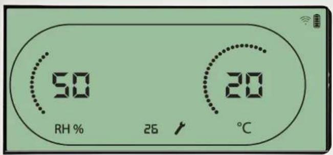
While flashing, the service interval can be increased by pressing RIGHT Button or decreased by pressing the LEFT Button.
Maximum 99 Weeks. Minimum is 1 week.
Alarms
Ambient condition Stand-by mode 2

Press for 3 seconds to enter user menu setup.

Press for 5 seconds to enter installer menu setup
Dantherm®
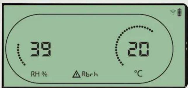
DRC1 enters stand-by mode 2 when ambient conditions are out of operation range. The display will show temperature and Rh readings when the unit is in stand-by mode 1. This state will only get corrected when the ambient temperature (abt) or ambient humidity (abrh) is in range, and can not be dismissed. You can enter menu setup to modify set point values – only in this case. While in Menu Setup, the alarm icon turn off and set point value will be shown instead of "Abt/Abrh" code on INFO line
Sensor fail

Press to see which sensor is defect.

Press to see which sensor is defect.
Dantherm®
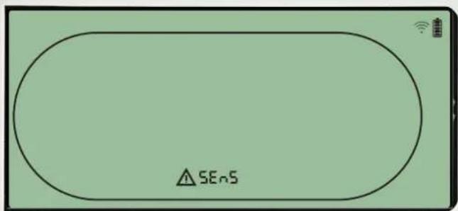
Dehumidifier is stopped because sensor failure is detected. Sensor Fail can not be dismissed from DRC1.
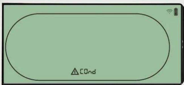
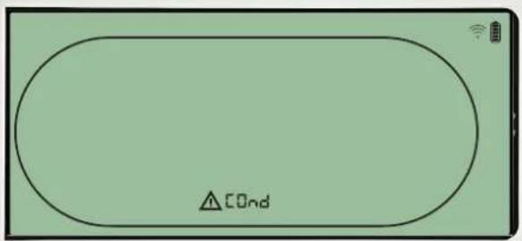
Use UP or DOWN button to see which sensor/sensors are defect If all sensors are defect these codes show in the following sequence: "COnd"↑↓ "EVAP" ↑↓ "RH/T" It is not possible to enter menu setup to modify set point values
Condensor sensor fail
Dantherm®
If condenser sensor is defected, then "COnd" code will be shown when pressing UP or DOWN when screen shows Sensor fail code "SEnS".
If no buttons pressed within 10 seconds then screen will again show "SEnS" again.
It is not possible to enter menu setup to modify set point.
Alarms continued
Evaporator sensor fail

Press to see which sensor is defect.

Press to see which sensor is defect.

Dantherm®

If evaporator sensor is defect, then "EVAP" code will be shown when pressing UP or DOWN during screen shows Sensor fail code "SEnS".
If Evaporator sensor ok, then no "EVAP" code shall be shown.
If no buttons pressed within 10 seconds then screen will show "SEnS" fail again.
It is not possible to enter menu setup to modify set point.
RH/T sensor fail

Press to see which sensor is defect.

Press to see which sensor is defect.
Dantherm®
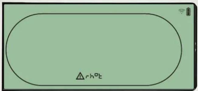
If RH/T sensor is defect, then "rh°t" code will be shown when pressing UP or DOWN during screen shows Sensor fail code "SEnS".
If RH/T sensor ok, then no "rh°t" code shall be shown.
If no buttons pressed within 10 seconds then screen will show "SEnS" fail again.
It is not possible to enter menu setup to modify set point.
Low pressure fail
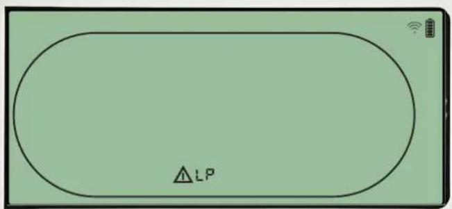
Dantherm®
Dehumidifier stopped because of Low Pressure detection.
Fail can not be dismissed from DRC1.
It is not possible to enter menu setup to modify set point.
Alarms continued
High pressure fail
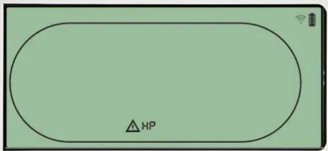
Dantherm®
Dehumidifier has stopped because of High Pressure detection.
Fail can not be dismissed from Remote panel.
It is not allowed to enter menu setup for modification of set points values.
Service alarm

Press for 5 seconds
to enter installer
menu setup
Dantherm®

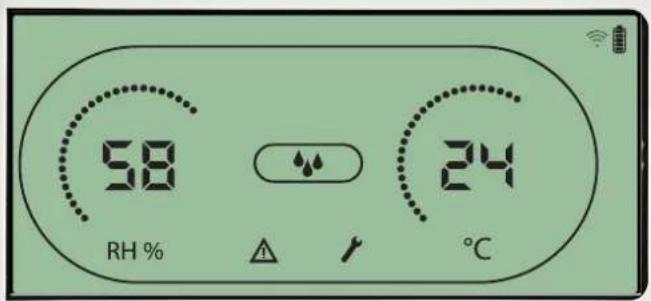
The Service icon will be shown when it is time for servicing the dehumidifier.
The service alarm does not affect the operation of dehumidifier.
To dismiss/reset service alarm:
- Press right for 5 seconds to enter the installer menu.
- Press DOWN/UP to navigate to service icon.
- Press RIGHT/LEFT to change setpoint from 0 to desired service interval.
- Confirm service interval by pressing enter.

Alarms priority
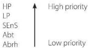
When more than one alarm is active the list above shows the priority of the alarms.
Kabellose Fernbedienung DRC1 (de)
Inhalt
Übersicht....14
Kopplung....15
Allgemeines 16
natural_image
Three-panel technical illustration showing a mechanical assembly with a tool inserted, no visible text or symbols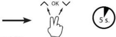
natural_image
3D architectural rendering of a server rack with visible door, panel, and base components (no text or symbols)Câble USB
Point final
Point final
natural_image
3D mechanical assembly diagram showing a component with an arrow pointing to a specific part (no visible text or symbols)
natural_image
3D mechanical assembly diagram showing internal components and mounting holes (no text or symbols)
natural_image
Exterior view of a modern office building (no signage)Dantherm®
natural_image
Interior view of a computer monitor with drive bays and a black arrow pointing to the screen (no visible text or symbols)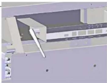
natural_image
3D mechanical assembly diagram showing internal components and mounting holes (no text or symbols)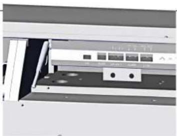
natural_image
Exterior view of a mechanical device with no visible text or symbolsnatural_image
Three-panel technical illustration showing internal components and a close-up of a device panel (no visible text or symbols)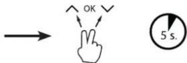
Fjernpanelets layout
natural_image
Three-panel technical illustration showing a mechanical assembly with a component inserted into a housing, no visible text or symbols.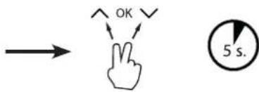
natural_image
Three-panel technical illustration showing a mechanical assembly with a bracket, a close-up view of a device panel, and a close-up of a control panel (no visible text or symbols)Dantherm®
natural_image
Three-panel technical illustration showing interior views of a mechanical or electronic device with no visible text or symbols.natural_image
3D mechanical assembly diagram showing internal components and a highlighted section (no text or symbols)
natural_image
3D mechanical assembly diagram showing internal components and mounting holes (no text or symbols)
natural_image
Interior view of a mechanical or electronic device with no visible text, numbers, or symbols.

Navigatie
Eindpunt
Eindpunt
Dantherm®
Maximum 99 weken. Minimum is 1 week.
Alarmen
Storing condensorsensor
Dantherm®


- Languages
- Wireless Remote Controller DRC1 (en)
- Table of contents
- Overview
- Warning
- Product description
- Antennae
- Mating
- Mating Mode
- Procedure
- Navigation
- Failed mating
- Standard readings
- General information
- Operation
- Fail Condition
- Locked remote
- User menu - Set points
- Dehumidifying set point
- Temperature set point
- Installer menu
- Fan set point.
- Service interval
- Alarms
- Ambient condition Stand-by mode 2
- Sensor fail
- Condensor sensor fail
- Alarms continued
- Evaporator sensor fail
- RH/T sensor fail
- Low pressure fail
- Kabellose Fernbedienung DRC1 (de)
- Inhalt
- Câble USB
- Fjernpanelets layout
- Navigatie
- Alarmen
- Storing condensorsensor
Brand : Dantherm
Model : DRC 1
Category : Air-conditioner