
PDSS 850 A1 - Pneumatic impact wrench PARKSIDE - Free user manual and instructions
Find the device manual for free PDSS 850 A1 PARKSIDE in PDF.

| Product type | Pneumatic impact wrench |
| Brand / Model | Parkside PDSS 850 A1 |
| Dimensions (L x W x H) | 186 x 215 x 68 mm |
| Weight | 1.96 kg |
| Power source | Compressed air (max. pressure 6.3 bar) |
| No-load speed | 7000 min⁻¹ |
| Tool holder | 1/2" (12.7 mm) square drive |
| Max. torque (loosening) | 850 Nm |
| Max. torque (tightening) | 750 Nm |
| Recommended torque | 550 Nm |
| Torque adjustment | 4 levels (0-250 / 250-500 / 500-750 / 500-850 Nm) |
| Rotation direction switch | Yes (right/left) |
| Sound pressure level (LpA) | 85.8 dB(A) (K=3 dB) |
| Sound power level (LWA) | 96.8 dB(A) (K=3 dB) |
| Vibrations (a_h) | 2.99 m/s² (K=0.61 m/s²) |
| Delivery contents | Impact wrench, 3 sockets (17/19/22 mm), extension bar, lubricator, oil bottle, carrying case, instructions |
| Lubrication | Before each use: 3-5 drops of special compressed air oil or via lubricator |
| Maintenance | Clean with a soft damp cloth; regular lubrication; check sockets |
| Storage | In the case, dry, frost-proof and dust-free |
| Safety | Wear goggles, gloves, hearing and respiratory protection; always disconnect before maintenance |
| Intended use | Fastening/loosening bolts (assembly, repair, wheel change) – private use only |
| Warranty | 3 years (Belgium) / statutory warranty (France) – see instructions |
Frequently Asked Questions - PDSS 850 A1 PARKSIDE
User questions about PDSS 850 A1 PARKSIDE
0 question about this device. Answer the ones you know or ask your own.
Ask a new question about this device
Download the instructions for your Pneumatic impact wrench in PDF format for free! Find your manual PDSS 850 A1 - PARKSIDE and take your electronic device back in hand. On this page are published all the documents necessary for the use of your device. PDSS 850 A1 by PARKSIDE.
USER MANUAL PDSS 850 A1 PARKSIDE
AIR IMPACT WRENCH PDSS 850 A1 DRUCKLUFT-SCHLAGSCHRAUBER PDSS 850 A1
CLÉ À CHOC PNEUMATIQUE PDSS 850 A1
IE CYGB NI MT
AIR IMPACT WRENCH
Translation of the original instructions
BEFR CH
CLÉ À CHOC PNEUMATIQUE
DRUCKLUFT-SCHLAGSCHRAUBER
Before reading, fold out the page with the images and familiarise yourself with all the features of the device.
DE AT CH
GB/IE/NI/CY/MT Operation and Safety Instructions Page 5
| DE/AT/CH Bedienungs- und Sicherheitshinweise Seite 19 | |||
| FR/BE/CH Instructions d'utilisation et consignes de sécurité Page | 33 | ||
| NL/BE | Bedienings- en veiligheidsinstructies | Pagina | 49 |
| CZ | Pokyny pro obsluhu a bezpečnostní pokyny | Strana | 63 |
| PL | Wskazówki użytkowania i bezpieczeństwa | Strona | 77 |
| SK | Návod na obsluhu a bezpečnostné pokyny | Strana | 91 |
| ES | Instrucciones de utilización y de seguridad | Página | 105 |
| DK | Betjenings- og sikkerhedsinstruktioner | Side | 119 |
| IT/MT/CH | Indicazioni per l’uso e per la sicurezza | Pagina | 133 |
| HU | Kezelési és biztonsági utalások | Oldal | 147 |
1. Introduction ...6
1.1 Intended Use 6
1.2 Scope of Delivery . 6
1.3 Equipment 6
1.4 Technical data 6
2. Safety instructions ...8
2.1 General safety rules ..8
2.2 Hazards due to ejected parts 9
2.3 Hazards due to entanglement ...9
2.4 Hazards during operation..9
2.5 Hazards due to repetitive movements ...10
2.6 Hazards due to accessories ...10
2.7 Hazards in the workplace...10
2.8 Dust and vapour hazards ...10......
2.9 Hazards due to noise 11
2.10 Hazards due to vibrations.... 11
2.11 Additional safety instructions for pneumatic machines 12
3. Before commissioning
3.1 Oil lubrication 12
3.1.1 Lubrication on the device 12
3.1.2 Lubrication with the compressed air lubricator 12
3.2 Connection to the compressed air source 13
3.3 Insert/change sockets nuts 13
4. Commissioning
4.1 Switch on 13
4.2 Switch off 13
4.3 Switching the direction of rotation.... 13
4.4 Setting the torque 14
5. Maintenance, cleaning and storage
6. Disposal
6.1 Environmental compatibility and disposal of materials 16
7. ROWI Germany GmbH Warranty
8. Service
9. Translation of the original declaration of conformity C€
AIR IMPACT WRENCH PDSS 850 A1
1. Introduction
We congratulate you on your new device purchase. You have thus opted for a high quality product. These Directions for Use are an integral part of this product. They contain important information for safety, use and disposal. Prior to the product use, make yourself familiar with all instructions for use and safety. Use the product only as described and only for the specified fields of use. If you hand on the product to third parties, also hand over all the product documents.
1.1 Intended Use
This device is suitable for simply tightening or inserting threaded fasteners during assembly or repair work and for loosening bolts when changing wheels. This tool may only be operated with a compressed air supply. The maximum permissible working pressure must not be exceeded. This device must not be operated with explosive or flammable gases! Any other use or modification of the appliance is considered improper use, harbours considerable accident risks and is also not permitted. We accept no liability for damage resulting from improper use. The appliance is intended for private use only and may not be used for commercial or industrial purposes.
1.2 Scope of Delivery
1 Air Impact Wrench
1 Oil bottle
1 Compressed air oiler
1 Plug nipple 1/4 " (6.35 mm - pre-assembled)
3 Socket nuts (17, 19, 22 mm)
1 Extension attachment
1 Carrying case
1 Instruction manual
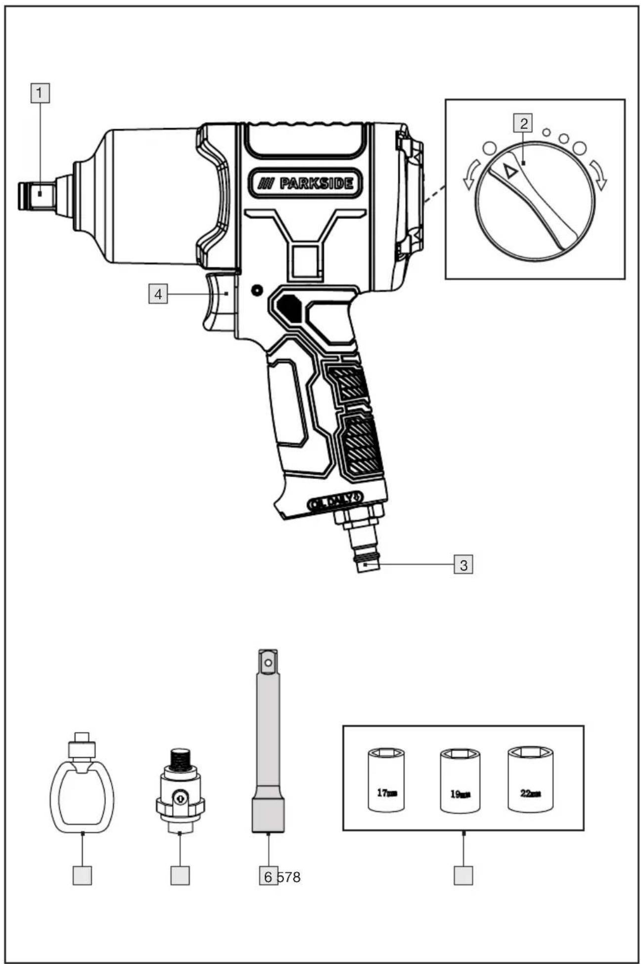
1.3 Equipment
1 Square mount
2 Direction of rotation changeover switch
3 Plug nipple
4 Trigger
5 Socket nuts
6 Extension attachment
7 Compressed air oiler
8 Oil bottle
1.4 Technical data
Rated air pressure: max. 6.3 bar
Rated speed: 7000 min -1
Tool holder: 1/2 “ (12,7 mm)
Torque ⬇: max. 750 Nm
Torque ⚙: max. 850 Nm
Recommended torque : 550 Nm


Dimensions:186 x 215 x 68 mm
Mass: 1960 g
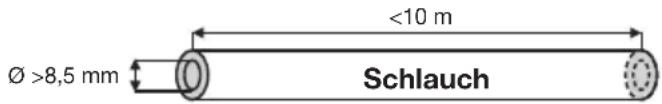
Recommended hose:
Noise emission values
Measured value for noise determined according to ISO 15744:
Sound pressure level LpA = 85.8 dB (A)
Uncertainty KpA = 3 dB
Sound power level LWA = 96.8 dB (A)
Uncertainty KWA=3 dB
WARNING!
The noise emission values specified in these instructions have been measured in accordance with a measurement method standardised in ISO 15744 and can be used to compare devices. The noise emission values will vary according to the use of the air tool and may in some cases be higher than the values given in these instructions. The noise emission exposure could be underestimated if the air tool is regularly used in such a way.
NOTE
For an accurate estimate of the noise emission load during a specific working period, the times when the appliance is switched off or is running but not actually in use should also be taken into account. This can significantly reduce the noise emission load over the entire working period.
Vibration emission value (declaration according to EN 12096)
Total vibration value determined according to ISO 28927-2
Vibrations*: ah = 2,99 m/s2
Uncertainty: K = 0,61 m/s 4
* Vibrations transmitted to the operator's hands
WARNING!
The vibration level specified in these instructions has been measured in accordance with a measurement method standardised in ISO 28927-2 and can be used for device comparison. The specified vibration emission value can also be used for an initial assessment of exposure.
The vibration emissions during actual use of the pneumatic tool may deviate from the specified values, depending on the way in which the pneumatic tool is used, in particular what type of workpiece is being machined and what kind of accessory is being used.
The vibration load could be underestimated if the pneumatic tool is regularly used in this way.
NOTE
Try to minimise the load as much as possible. Examples of measures to reduce the vibration load are:
- Maintain the appliance in accordance with these instructions,
■ wearing gloves when using the tool,
■ limiting the working time or planning your work steps so that you do not have to use highly vibrating devices for days on end.
All parts of the operating cycle must be taken into account (for example, times when the pneumatic tool is switched off and times when it is switched on but not under load).
Explanations of all symbols to be found on the machine for screw connections
  | WARNINGRead the operating instructions before commissioning. |
 | Direction of rotation |
 | Wear eye protection |
 | Wear respiratory protection |
 | Wear hearing protection |
 | Wear protective gloves. |
2. Safety instructions
NOTE
When using pneumatic tools, basic safety precautions must be followed to eliminate the risk of fire, electric shock and personal injury.
The information provided in these operating instructions is an important, but not the sole basis for the safe use of the machine. The hazards indicated are foreseeable for the general use of hand-held pneumatic impact wrenches. However, the user must also assess specific risks that may arise from each use.
Residual risks
Even if you operate the appliance in accordance with the instructions, there are always residual risks. The following hazards may occur in connection with the design and construction of this appliance:
■ Hose kickback in the event of improper handling.
- Risk of falling due to compressed air hoses lying around.
■ Hazard due to compressed air hoses bouncing around.
Reduce the risk of an accident by carefully and correctly using the device and by following all instructions. Keep your work area clean and well lit. Cluttered and dark areas invite accidents!
2.1 General safety rules
- Multiple hazards! The safety instructions must be read and understood before setting up, operating, repairing, maintaining or replacing accessories on the machine for screw connections, as well as before working near the machine. Failure to do so may result in serious physical injury.
- The machine for bolted joints should only be set up, adjusted or used by suitably qualified and trained operators.
This machine for bolted connections must not be modified. Modifications can reduce the effectiveness of the safety measures and increase the risks for the operator.
■ The safety instructions must not be lost. Give them to the operator.
■ Never use damaged machines. - Check signs and labelling for completeness and legibility. The machine must be inspected regularly to check that the machine is labelled with the clearly legible ratings and markings required in these operating instructions. The user must contact the manufacturer to obtain replacement plates if necessary.
2.2 Hazards due to ejected parts
If the workpiece or accessories or even the machine tool itself break, parts can be ejected at high speed.
- Impact-resistant eye protection must always be worn when operating the machine for screw connections or when replacing accessories on the machine. The degree of protection required should be assessed separately for each individual use.
■ Ensure that the workpiece is securely fastened.
2.3 Hazards due to entanglement
There is a risk of suffocation, scalping and/or cuts if loose-fitting clothing, jewellery, necklaces, hair or gloves are not kept away from the machine and its accessories.
Gloves can get caught in the rotating drive, which can cause injuries or breaks to the fingers.
- With rotating drive mounts and extensions, rubberised or metal-reinforced gloves can easily be caught/unwrapped.
- Do not wear loose-fitting gloves or gloves with cut or worn glove fingers.
■ Never hold the drive, the socket or the drive extension.
- Keep your hands away from the rotating drive.
2.4 Hazards during operation
- When using the machine, the operator's hands may be exposed to crushing, impact, cutting, abrasion and heat hazards. Wear suitable gloves to protect your hands.
The operator and maintenance personnel must be physically capable of handling the size, mass and power of the machine. - Hold the machine correctly: Be ready to counteract the usual or sudden movements - have both hands ready.
■ Make sure that your body is balanced and that you have a secure hold.
In cases where tools are required to absorb the reaction torque, it is recommended to use a suspension device whenever possible. If this is not possible, side handles are recommended for machines with a straight handle and machines with a pistol grip. In any case, it is recommended to use aids to absorb the reaction torque if it is greater than 4 Nm for straight-handled machines, greater than 10 Nm for pistol-grip machines and greater than 60 Nm for angle screwdrivers.
In the event of an interruption in the power supply, release the trigger.
■ Only use the lubricants recommended in these operating instructions.
■ Fingers can be crushed in nut drivers with an open flat head. - Do not use the tool in confined spaces and ensure that your hands are not crushed between the machine and the workpiece, especially when unscrewing.
2.5 Hazards due to repetitive movements
- When using a bolting machine to carry out work-related activities, the operator may experience unpleasant sensations in the hands and arms, neck and shoulders or other parts of the body.
- When using a bolting machine, the operator should adopt a comfortable posture, ensuring a secure footing and avoiding awkward postures or postures that make it difficult to maintain balance. The operator should change posture during long periods of work, which can help to avoid discomfort and fatigue.
If the operator experiences symptoms such as persistent or recurring discomfort, aches, throbbing, pain, tingling, numbness, burning or stiffness, these signs should not be ignored. The operator should consult a suitably qualified medical practitioner.
2.6 Hazards due to accessories
- Disconnect the machine from the power supply for screw connections before installing or replacing the machine tool or accessories.
- Do not touch impact sockets or accessories during the impact process as this can increase the risk of cutting, burning or injury from vibrations.
- Only use accessories and consumables of the sizes and types recommended in these operating instructions. Do not use any other types or sizes of accessories and consumables.
- Only use impact sockets in good working condition, as poor condition of hand sockets and accessories can cause them to break and be ejected when used with impact wrenches.
2.7 Hazards in the workplace
■ Slipping, tripping and falling are the main causes of injuries in the workplace. Pay attention to surfaces that may have become slippery through the use of the machine and to tripping hazards caused by the air hose.
■ Proceed with caution in unfamiliar surroundings. There may be hidden hazards due to power cables or other supply lines.
This machine for screw connections is not intended for use in potentially explosive atmospheres and is not insulated against contact with electrical power sources.
- Ensure that there are no electrical cables, gas pipes, etc. that could cause a hazard if the machine is damaged during use.
2.8 Dust and vapour hazards
The dusts and vapours generated from the use of bolting machines can cause adverse health effects (such as cancer, birth defects, asthma and/or dermatitis); it is essential to carry out a risk assessment in relation to these hazards and implement appropriate control mechanisms.
The risk assessment should include the dust generated during use of the machine and the dust that may be stirred up in the process.
The exhaust air must be discharged in such a way that the swirling up of dust in dusty
environments is minimised.
If dusts or vapours are generated, the main task must be to control them at the point of release.
All built-in parts or accessories of the machine intended to collect, extract or suppress flying dust or vapours should be used and maintained in accordance with the manufacturer's instructions.
■ Use respiratory protective equipment as required by occupational health and safety regulations.
2.9 Hazards due to noise
- Exposure to high noise levels can lead to permanent hearing damage, hearing loss and other problems such as tinnitus (ringing, buzzing, whistling or humming in the ears) if hearing protection is inadequate; it is essential to carry out a risk assessment in relation to these hazards and implement appropriate control mechanisms.
- Suitable control mechanisms for risk minimisation include measures such as the use of insulating materials to prevent "ringing noises" occurring on the workpieces.
■ Use hearing protection equipment in accordance with the instructions of the local occupational health and safety regulations.
The machine for bolted joints must be operated and maintained in accordance with the recommendations contained in these instructions in order to avoid an unnecessary increase in the noise level.
If the pneumatic tool has a silencer, always ensure that it is in place and in good working condition when operating the pneumatic tool.
The consumables/machine tools must be selected, maintained and replaced in accordance with the recommendations in this manual in order to avoid an unnecessary increase in the noise level.
2.10 Hazards due to vibrations
■ Exposure to vibrations can cause damage to the nerves and disrupt blood circulation in the hands and arms.
- Keep your hands away from the nut driver sockets.
- Wear warm clothing when working in cold environments and keep your hands warm and dry.
If you notice numbness, tingling or pain in your fingers or hands or if the skin on your fingers or hands turns white, stop using the machine for screw connections and consult a doctor.
The machine for bolted joints must be operated and maintained in accordance with the recommendations contained in these instructions in order to avoid unnecessary amplification of vibrations.
- Do not use worn or poorly fitting sockets and extensions, as this is very likely to lead to a considerable amplification of the vibrations.
The consumables/machine tools must be selected, maintained and replaced in accordance with the recommendations in this manual in order to avoid unnecessary amplification of vibrations.
If possible, socket fittings should be used.
- Whenever possible, use a stand, a clamp or a levelling device to support the weight of the machine.
- Hold the machine with a not too tight but secure grip while maintaining the required hand reaction forces, as the risk of vibration generally increases with increasing grip force.
2.11 Additional safety instructions for pneumatic machines
■ Compressed air can cause serious injuries:
- When the machine is not in use, before replacing accessories or carrying out repair work, always shut off the air supply, depressurise the air hose and disconnect the machine from the compressed air supply.
Never direct the airflow towards yourself or other people.
- Flapping hoses can cause serious injuries. Therefore, always check that the hoses and their fasteners are undamaged or have not come loose.
- Cold air must be removed from the hands.
- Do not use quick-release couplings on the tool inlet for impact and impulse wrenches. Only use threaded hose connections made of hardened steel (or a material of comparable impact resistance).
If universal swivel couplings (claw couplings) are used, locking pins must be fitted and use Whipcheck hose locks to provide protection in the event of failure of the connection between the hose and the machine or between hoses.
■ Ensure that the maximum pressure specified on the machine is not exceeded.
In torque-controlled machines with continuous rotation, the air pressure has safety-relevant effects on the performance. Therefore, requirements for the length and diameter of the hose must be specified.
■ Never carry air-powered machines by the hose.
3. Before commissioning
3.1 Oil lubrication
Regular lubrication prevents friction and corrosion damage. There are two ways to lubricate your device.
3.1.1 Lubrication on the device
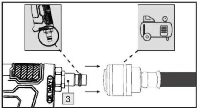
- Lubricate the pneumatic tool before each use.
- Add 3-5 drops of special compressed air oil to the plug nipple 3.
This is enough for 15 minutes of continuous use.
3.1.2 Lubrication with the compressed air lubricator
The compressed air lubricator 7 supplied lubricates the compressed air tool continuously and optimally.
Check the functionality and strength of the compressed air oiler 7 before each use. Otherwise there is a risk of injury as the product may become defective or the oil may spray out.
- Hold the compressed air oiler 7 so that the inlet screw ⊕ is pointing upwards.
- Firstunscrew 5 the inlet screw from the compressed air oiler 7.
Fill the compressed air oiler 7 with a sufficient amount of oil.
■Screw the inlet screw back in.
■ Now insert the compressed air oiler 7 into the pneumatic tool and screw it tight.
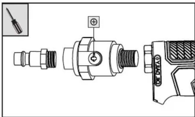
NOTE: Wrap all threaded connections with Teflon tape (not supplied).
NOTE: We recommend special compressed air oil, e.g. from GÜDE, Metabo, E-COLL or Einhell.
NOTE: You can also use a compressed air maintenance unit for lubrication. This guarantees regular lubrication.
3.2 Connection to the compressed air source
The machine for screw connections may only be operated with cleaned, oil-misted compressed air.
■ The compressed air line must not contain any condensation.
The maximum working pressure of 6.3 bar must not be exceeded.
- Ensure that the working pressure is not lower than 6.3 bar. This machine for bolted joints is only designed for this working pressure.
■ The compressor must be equipped with a pressure reducer to regulate the working pressure.
■ Connect the plug-in nipple 3 to the supply hose of a compressor.
3.3 Insert/change sockets nuts
■ Disconnect the machine from the power supply for screw connections before installing or replacing the machine tool or accessories.
- Attach one of the socket nuts 5 to the square drive 1. Ensure that the socket wrench is securely seated.
- Optionally, the extension attachment can be used between the socket nuts and the square receiver 1.
4. Commissioning
4.1 Switch on
■ Press the trigger 4 to switch on the device.
4.2 Switch off
■ Release the trigger 4. Always disconnect the tool from the air supply after finishing work.
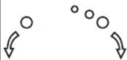
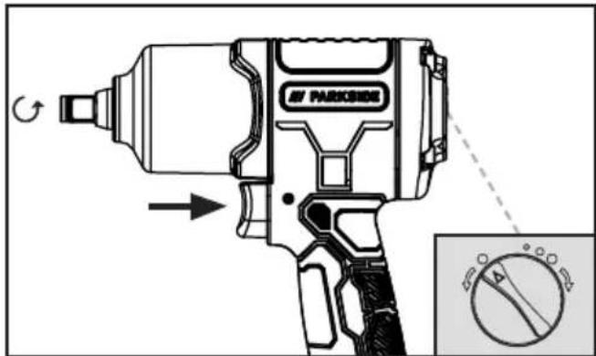
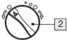
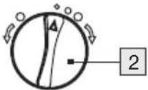
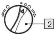
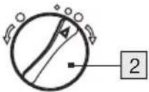
4.3 Switching the direction of rotation
WARNING
The direction of rotation switch 2 must only be adjusted when the device is at a standstill.
- To tighten nuts, for example, turn the direction of rotation switch 2 to the right to one of the three torque settings for clockwise rotation. This sets the clockwise rotation mode. The square drive 1 turns in a clockwise direction.
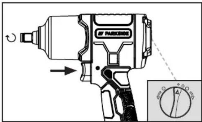
For example, to loosen nuts, turn the direction of rotation switch 2 completely to the left. This sets the anti-clockwise rotation mode. The square drive 1 turns in an anti-clockwise direction.
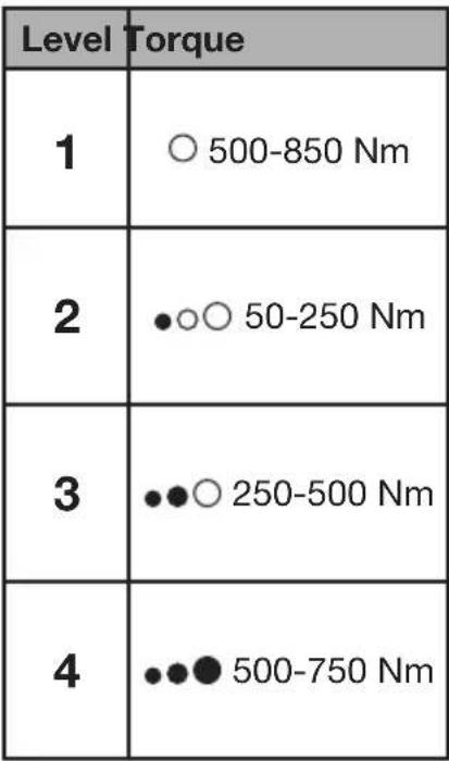
4.4 Setting the torque
WARNING
The torque setting on the direction of rotation changeover switch 2 must only be adjusted when the device is at a standstill.
- Turn the direction of rotation switch 2 to the appropriate level to achieve the desired torque.
NOTE: Depending on the material, size and condition of the bolts and nuts to be turned, the torque performance data may vary.
 |  |
 | |
 | |
 |
5. Maintenance, cleaning and storage
WARNING! RISK OF INJURY! Disconnect the appliance from the compressed air source before carrying out maintenance work.
The following points can be regarded as a list of operating steps that the user should carry out for the maintenance, cleaning and storage of the appliance.
■ Regular preventive maintenance ensures the safety of the machine for bolted joints.
- Regardless of the number of operations or activations, maintain and clean the appliance after each use.
- Observe the disposal instructions in these operating instructions. Improper disposal can damage the environment or your health.
- Sufficient and constantly intact oil lubrication is crucial for optimum function (see chapter on oil lubrication).
- Check the speed after each use. The speed must be checked regularly.
- Carry out a simple check of the vibration level after every service and maintenance.
- Only use original spare or replacement parts from the manufacturer, otherwise the health and safety of operating personnel may be impaired. If in doubt, please contact our service team.
Before servicing, clean the appliance of hazardous substances that have been deposited on it (due to work processes). Avoid any skin contact with these substances. If the skin comes into contact with hazardous dusts, this can lead to severe dermatitis. If dust is generated or stirred up during maintenance work, it can be inhaled.
■ Always wear protective gloves and a protective mask!
- Only clean the housing of the device with a slightly damp, soft cloth. Never use abrasive and/or abrasive cleaning agents.
- The appliance may only be operated and maintained by trained personnel. Repairs may only be carried out by qualified persons.
Inspections, adjustments and maintenance work should be carried out by the same person or their deputy wherever possible and documented in a maintenance log.
- Store the appliance and the operating instructions in the carrying case supplied. Store the device and its accessories in a dark, dry, dust-free and frost-free place.
- Store oil bottle 8 in a cool place. Keep container tightly closed in a dry, well-ventilated place. Keep away from fire and heat. Store away from food and strong oxidising agents. Store locked up.
6. Disposal
- The pneumatic power tool, accessories and packaging* should be recycled in an environmentally friendly manner.
- For information on how to dispose of the discarded machine and accessories, please contact your local council or town/city administration.


The packaging is made of environmentally friendly materials that you can dispose of at your local recycling centres.

The Triman logo is valid in France only.

Observe the labelling of the packaging materials when separating waste; these are marked with abbreviations (a) and numbers (b) with the following meaning: 1–7: Plastics/20–22: Paper and cardboard/80-98: Composites.
6.1 Environmental compatibility and disposal of materials
Lubricating oil must not get into the soil, water or waste water. Lubricating oil is hazardous waste and must be disposed of accordingly. Observe the local regulations. Dispose of the lubricating oil and packaging containing residues at your local collection point, petrol station or oil dealer.
* Non-contaminated or cleaned packaging can be recycled.
7. ROWI Germany GmbH Warranty
Dear Customer,
This appliance has a 3-year warranty valid from the date of purchase. If this product has any faults, you, the buyer, have certain statutory rights. Your statutory rights are not restricted in any way by the warranty described below.
Warranty conditions
The validity period of the warranty starts from the date of purchase. Please keep your original receipt in a safe place. This document will be required as proof of purchase.
If any material or production fault occurs within three years of the date of purchase of the product, we will either repair or replace the product for you or refund the purchase price at our discretion. This warranty service is dependent on you presenting the defective appliance and the proof of purchase (receipt) and a short written description of the fault and its time of occurrence.
If the defect is covered by the warranty, your product will either be repaired or replaced by us. The repair or replacement of a product does not signify the beginning of a new warranty period.
Warranty period and statutory claims for defects
The warranty period is not prolonged by repairs effected under the warranty. This also applies to replaced and repaired components. Any damage and defects present at the time of purchase must be reported immediately after unpacking. Repairs carried out after expiry of the warranty period shall be subject to a fee.
Scope of the warranty
This appliance has been manufactured in accordance with strict quality guidelines and inspected meticulously prior to delivery.
The warranty covers material faults or production faults. The warranty does not extend to product parts subject to normal wear and tear or fragile parts such as switches, batteries or those made of glass.
The warranty does not apply if the product has been damaged, improperly used or improperly maintained. The directions in the operating instructions for the product regarding proper use of the product are to be strictly followed. Uses and actions that are discouraged in the operating instructions or which are warned against must be avoided.
This product is intended solely for private use and not for commercial purposes. The warranty shall be deemed void in cases of misuse or improper handling, use of force and modifications/repairs which have not been carried out by one of our authorised Service centres.
Warranty claim procedure
To ensure quick processing of your case, please observe the following instructions:
For all enquiries, please have the receipt and item number (IAN 478353_2404) ready as proof of purchase.
Please refer to the type plate on the product, an engraving on the product, the title page of your instructions (bottom left) or the sticker on the back or underside of the product for the article number.
- Should functional faults or other defects occur, please first contact the service department named below by telephone or e-mail.
- You can then send a product recorded as defective to the service address provided to you free of charge, enclosing the proof of purchase (receipt) and stating what the defect is and when it occurred.

PDF ONLINE
parkside-diy.com
You can view and download these and many other manuals at parkside-diy.com. This QR code will take you directly to parkside-diy.com. Select your country and use the search mask to look for the manuals. Entering the article number (IAN) 478353_2404 will take you to the operating instructions for your article.
8. Service
If any problems occur during use of your ROWI Germany product, please proceed as follows:
Contact us
You can contact the service team of ROWI Germany at:
ROWI Germany GmbH
(free call from a German landline)
IAN 478353_2404
Most problems can be resolved with the skilled technical support of our Service Team.
9. Translation of the original declaration of conformity C€
We, ROWI Germany GmbH, Werner-von-Siemens-Str. 27, 76694 Forst, Germany, hereby declare that this product complies with the following standards, standardising documents and EU directives:
Machinery Directive: 2006/42/EG
Applied harmonised standards:
EN ISO 11148-6:2012
Device designation:
Air Impact Wrench
Model number: PDSS 850 A1
Year of manufacture: 10/2024
Lot number: IAN 478353_2404
Person responsible for documentation:
Marc Stockenberger
Town.: Forst
Date/Manufacturer's signature: 06.08.2024

Marc Stockenberger
Managing Director
We reserve the right to make technical changes in the interest of further development.
1. Einleitung ...20
DRUCKLUFT-SCHLAGSCHRAUBER PDSS 850 A1
1. Einleitung
4.1 Einschalten
WAARSCHUWING! RISICO OP LETSEL!
3.3 Insertar/cambiar enchufes
2.4 Farer under drift

- AIR IMPACT WRENCH
- CLÉ À CHOC PNEUMATIQUE
- DRUCKLUFT-SCHLAGSCHRAUBER
- DE AT CH
- INTRODUCTION ...6
- SAFETY INSTRUCTIONS ...8
- BEFORE COMMISSIONING
- COMMISSIONING
- MAINTENANCE, CLEANING AND STORAGE
- DISPOSAL
- ROWI GERMANY GMBH WARRANTY
- SERVICE
- TRANSLATION OF THE ORIGINAL DECLARATION OF CONFORMITY C€
- AIR IMPACT WRENCH PDSS 850 A1
- INTRODUCTION
- 1.1 INTENDED USE
- 1.2 SCOPE OF DELIVERY
- 1.3 EQUIPMENT
- 1.4 TECHNICAL DATA
- NOISE EMISSION VALUES
- WARNING
- NOTE
- VIBRATION EMISSION VALUE (DECLARATION ACCORDING TO EN 12096)
- EXPLANATIONS OF ALL SYMBOLS TO BE FOUND ON THE MACHINE FOR SCREW CONNECTIONS
- SAFETY INSTRUCTIONS
- RESIDUAL RISKS
- 2.1 GENERAL SAFETY RULES
- 2.2 HAZARDS DUE TO EJECTED PARTS
- 2.3 HAZARDS DUE TO ENTANGLEMENT
- 2.4 HAZARDS DURING OPERATION
- 2.5 HAZARDS DUE TO REPETITIVE MOVEMENTS
- 2.6 HAZARDS DUE TO ACCESSORIES
- 2.7 HAZARDS IN THE WORKPLACE
- 2.8 DUST AND VAPOUR HAZARDS
- 2.9 HAZARDS DUE TO NOISE
- 2.10 HAZARDS DUE TO VIBRATIONS
- 2.11 ADDITIONAL SAFETY INSTRUCTIONS FOR PNEUMATIC MACHINES
- 3.1 OIL LUBRICATION
- 3.1.1 LUBRICATION ON THE DEVICE
- 3.1.2 LUBRICATION WITH THE COMPRESSED AIR LUBRICATOR
- 3.2 CONNECTION TO THE COMPRESSED AIR SOURCE
- 3.3 INSERT/CHANGE SOCKETS NUTS
- 4.1 SWITCH ON
- 4.2 SWITCH OFF
- 4.3 SWITCHING THE DIRECTION OF ROTATION
- 4.4 SETTING THE TORQUE
- 6.1 ENVIRONMENTAL COMPATIBILITY AND DISPOSAL OF MATERIALS
- WARRANTY CONDITIONS
- WARRANTY PERIOD AND STATUTORY CLAIMS FOR DEFECTS
- SCOPE OF THE WARRANTY
- WARRANTY CLAIM PROCEDURE
- CONTACT US
- EINLEITUNG ...20
- DRUCKLUFT-SCHLAGSCHRAUBER PDSS 850 A1
- EINLEITUNG
- 4.1 EINSCHALTEN
- WAARSCHUWING! RISICO OP LETSEL
- 3.3 INSERTAR/CAMBIAR ENCHUFES
- 2.4 FARER UNDER DRIFT
Brand : PARKSIDE
Model : PDSS 850 A1
Category : Pneumatic impact wrench