
TRHV 2000 A1 - Electric heating TRONIC - Free user manual and instructions
Find the device manual for free TRHV 2000 A1 TRONIC in PDF.

| Product Type | Electric fan heater |
| Brand | Tronic |
| Model | TRHV 2000 A1 |
| Heating Power | 2000 W |
| Input Voltage | 220-240 V ~ 50/60 Hz |
| Power Cord Length | 1.8 m |
| Number of Operating Modes | 4: Power, Sleep, Nature, ECO |
| Ventilation Levels | 20 (fan only) / 10 (heating) |
| Adjustable Temperature Range | 5 °C to 35 °C |
| Oscillation Function | Yes, 4 angles: 30°, 60°, 90°, 120° |
| Timer | Up to 12 hours |
| LED Ambient Light | 5 colors + automatic change, 4 brightness levels |
| Remote Control | Yes, with included CR2025 battery |
| Anti-freeze Protection | Yes, automatic operation below 7 °C, stops above 10 °C |
| Automatic Safety Shut-off | After 12 hours of continuous operation |
| Tip-over Protection | Yes, automatic shut-off if tilted >30° |
| Recommended Heating Area | Up to 18 m² (well-insulated room) |
| Noise Level | 55.9 dB(A) |
| Standby Consumption | 0.46 W |
| Protection Class | Class II |
| Available Colors | White (standard model) |
| Weight (approx.) | 2.5 kg |
| Dimensions (L × H × D, approx.) | 25 × 40 × 25 cm |
Frequently Asked Questions - TRHV 2000 A1 TRONIC
User questions about TRHV 2000 A1 TRONIC
0 question about this device. Answer the ones you know or ask your own.
Ask a new question about this device
Download the instructions for your Electric heating in PDF format for free! Find your manual TRHV 2000 A1 - TRONIC and take your electronic device back in hand. On this page are published all the documents necessary for the use of your device. TRHV 2000 A1 by TRONIC.
USER MANUAL TRHV 2000 A1 TRONIC
FAN HEATER TRHV 2000 A1 HEIZVENTILATOR TRHV 2000 A1 VENTILATEUR-CHAUFFAGE TRHV 2000 A1
IEGB NI CY MT
FAN HEATER
Operating and Safety Instructions This product is only suitable for well insulated spaces or occasional use.
BEFR CH
VENTILATEUR-CHAUFFAGE
Before reading, fold out the page with the images and familiarise yourself with all the features of the device.
DE AT CH
GB/IE/NI/CY/MT Operation and Safety Instructions Page 5
1. Introduction 7
1.1 Intended Use....7
1.2 Scope of Delivery....7
1.3 Equipment....7
1.4 Technical Data....7
2. Safety indications 10
2.1 General safety indications: Safety of electrical appliances for home use...10.....
2.2 Specific safety indications: Special requirements for room heating appliances...1.1.....
2.3 Information about batteries...12.....
3. Before you start the device 14
3.1 Device Installation...14
3.2 Remote control: How to insert or change the battery.... 14
4. Starting Up 14
4.1 Standby mode....14
5. Control on the device 14
5.1 Switch on the device ⏻ 14
5.2 Switch off the device 15
5.3 Select operating mode M 15
5.4 Select ventilation levels 15
5.5 Timer function 16
5.6 Oscillation function 16
5.7 Select heating levels 16
5.8 Set temperature 16
5.9 LED atmospheric light function 17
5.9.1 Setting the brightness of the LED atmospheric light 17
5.10 Frost monitor function....17
6. Control with the remote control ...17.
6.1 Switch on the device ⏻ 17....
6.2 Switch off the device ⏻ 17....
6.3 Select operating mode M ...17....
6.4 Select ventilation levels 18
6.5 Timer function ☒ ...18
6.6 Oscillation function 📋 18
6.7 Select heating levels 1.8
6.8 Set temperature ⏻ 19
6.9 LED atmospheric light function ⚙ 19
6.9.1 Setting the brightness of the LED atmospheric light 19
7. Troubleshooting 20
8. Maintenance, cleaning and storage 21
9. Disposal 21
10. Resource efficiency 21
10.1 Availability and maximum delivery times for spare parts 21
11. ROWI Germany GmbH Warranty 22
12. Service 23
FAN HEATER TRHV 2000 A1
1. Introduction
We congratulate you on your new device purchase. You have thus opted for a high quality product. These Directions for Use are an integral part of this product. They contain important information for safety, use and disposal. Prior to the product use, make yourself familiar with all instructions for use and safety. Use the product only as described and only for the specified fields of use. If you hand on the product to third parties, also hand over all the product documents.
1.1 Intended Use
This appliance is only intended for heating closed and dry rooms during the transitional period. It can be used as additional heating or temporary heating in well-insulated rooms up to approx. 18 m^2 in size. The appliance is not intended for use in rooms where special conditions prevail, such as corrosive or explosive atmospheres (dust, steam or gas). Do not use the device outdoors. Any other use or modification of the appliance is considered improper use and involves considerable risk of accidents. We accept no liability for damage resulting from improper use. The appliance is intended for private use only and not for commercial use.
1.2 Scope of Delivery
1 Fan heater TRHV 2000 A1
1 Remote control
1 Instruction manual
1.3 Equipment
Fan
1 On/off button
2 Timer button
3 Display
4 Heating level button
5 Temperature button
6 Brightness level button
7 Oscillation button
8 Mode button
9 Ventilation level button
10 LED atmospheric light
11 Supply cable
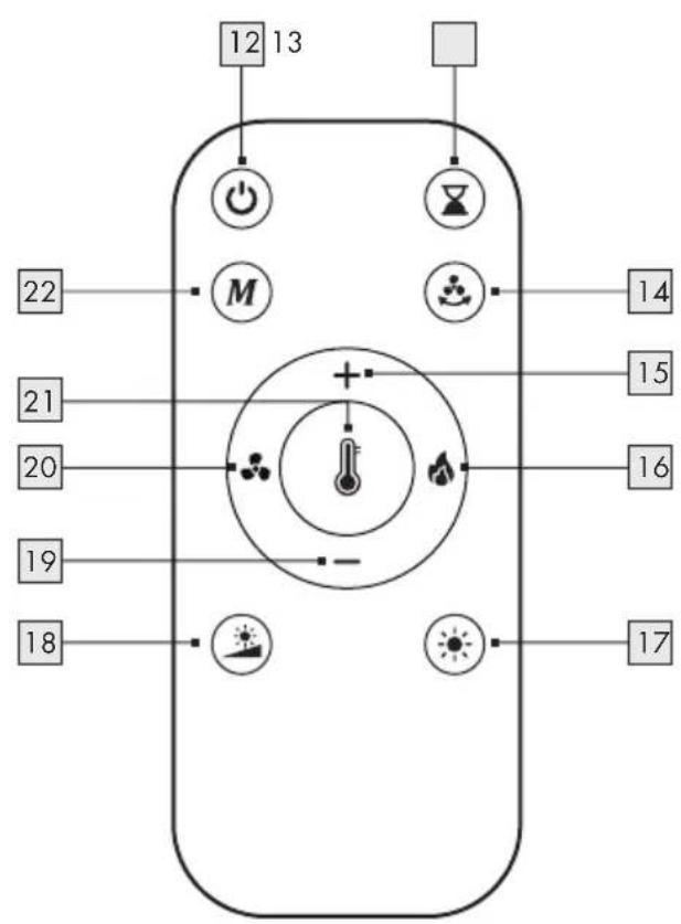
Remote control
12 On/off button
13 Timer button
14 Oscillation button
15 Plus button
16 Heating level button
17 LED atmospheric light
18 Brightness level button
19 Minus button
20 Ventilation level button
21 Temperature button
22 Mode button
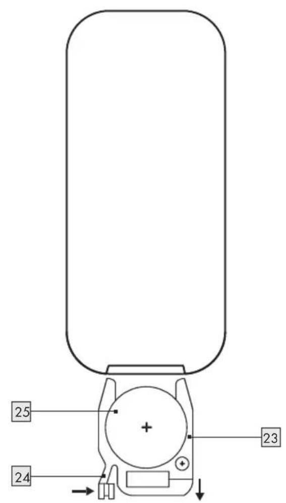
23 Battery compartment
24 Tab
25 Button cell (battery)
1.4 Technical Data
Input voltage: 220-240 V
Rated frequency: 50-60 Hz
Output power: 2000 W
Protection class:
Mains cable length: 1,8 m
Remote control (only for use with Fan heater TRHV 2000 A1)

Battery supply: 3 V (Direct current) CR2025

: Lithium-Batterie
Battery manufacturer
DONGGUAN TIANQIU ENTERPRISE CO., LTD TianQiu Industrial Park, Xinji Industrial Zone, Machong Town, Dongguan, GuangDong, P.R. China Tel: 0086-769-81210216
Mail: gd@gdtiangiu.com
Website: http://www.tmmq.cn
Information requirements for electric local space heaters
Model identifier(s): TRHV 2000 A1
Item Symbol Value Unit
Heat output
| Nominal heat output P | nom | 2.0 kW |
| Minimum heat output (indicative) | Pmin | N/A kW |
| Maximum continuous heat output | Pmax,c | 2.0 kW |
Power consumption
| In off mode P | o | N/A W | |
| In standby mode P | sm | 0.46 | W |
| In idle mode P | idle | 0.46 | W |
| In network standby | Pnsm | N/A W |
Standby mode with display information [no] or status
Seasonal space heating energy efficiency in active _S,on 91.5 % mode
Item
Unit
Type of heat output/room temperature control (select one)
single stage heat output and no room temperature control [no]
Two or more manual stages, no room temperature control [no]
with mechanic thermostat room temperature control [no]
with electronic room temperature control [yes]
electronic room temperature control plus day timer [no]
electronic room temperature control plus week timer [no]
Other control options (multiple selections possible)
room temperature control, with presence detection [no]
room temperature control, with open window detection [no]
with distance control option [no]
with adaptive start control [no]
with working time limitation [yes]
with black bulb sensor [no]
self-learning functionality [no]
control accuracy [no]
ROWI Germany GmbH Werner-von-Siemens-Str. 27
76694 Forst
GERMANY
Required information for comfort fans:
| Designation Symbol Value Unit | |||
| Maximum volume flow | F 14.6 m | ^3 /min | |
| Fan Power consumption | P 27.1 W | ||
| Service ratio | SV 0.54 | (m3/min)/W | |
| Power con-sumption in standby mode | P_SB | 0.46 W | |
| Fan Sound power level | L_WA | 55.9 dB(A) | |
| Maximum air speed | c 3.0 m/s | ||
| Seasonal electricity consumption | Q 9.19 kWh/a | ||
| Measurement standard for determining service ratio | IEC 60879:2019 | ||
ROWI Germany GmbH
2. Safety indications

Read all the safety indications and instructions.
Failure to adhere to the safety indications and instructions may cause serious injuries and/or property damages.
Please keep all the safety indications and instructions for future use.
2.1 General safety indications:
Safety of electrical appliances for home use
This appliance can be used by children of 8 years and more as well as by persons with reduced physical, sensory or mental abilities or lacking experience and knowledge, if they are supervised or are instructed in the safe use of the appliance and understand the ensuing dangers. Children may not play with the appliance. The cleaning and maintenance of the appliance by the user may not be carried out by children not under supervision.
- No measures need to be taken by the user to set the product to 50 or 60 Hz or 220 or 240 V. The product adjusts automatically to the correct frequency or voltage.
If the supply cable for this appliance is damaged, it must be replaced by the manufacturer or his customer service or a similarly qualified person in order to avoid any dangers.
2.2 Specific safety indications:
Special requirements for room heating appliances
WARNING! Do not cover!
To avoid the heater overheating, it must not be covered.
- The heater may not be placed directly beneath a wall mains socket.
- Do not use this heater in the direct vicinity of a bathtub, a shower or a swimming pool.
- Do not commission an appliance which has been dropped.
- Do not use if visible signs of damages can be seen on the heater.
■ The heater must be placed on a firm, flat and level base.
■ WARNING! The heater may not be used in small rooms where people live who are not able to leave the room independently unless constant monitoring is guaranteed. - WARNING! Fire danger! To reduce the danger of fire, keep textiles, curtains and other combustible materials at least 1 m away from the air outlet.
- Children of less than 3 must be kept away unless they are constantly monitored.
Children between 3 and 8 may only switch the appliance on and off if they are under supervision or have been instructed in the safe use of the appliance and have understood the resulting dangers, with the prerequisite that the appliance is placed or installed in its normal operating position. Children between 3 and 8 may not plug the plug into the mains socket, control the appliance, clean it and/or not carry out user maintenance.
Warning against hot surfaces!
ATTENTION: Some parts of the product may become extremely hot and cause burns. Special care is required if children and vulnerable persons are present.
The appliance is only suitable for indoor operation.
Danger to life due to electrical current!
Danger to life in case of contact with live cables or components!
2.3 Information about batteries
Keep out of reach of children.
Swallowing can lead to injury, perforation of soft tissue and to death. Severe burns can occur within 2 hours of swallowing. Seek medical advice immediately.
- Incorrect use of batteries may result in fire, explosion, leakage of dangerous substances, or other hazard!
- Do not throw batteries into the fire and do not expose them to high temperatures.
- Do not open, deform or short-circuit the batteries. Otherwise, the contained chemicals can leak out of them.
-
Do not try to recharge batteries. Recharging is only allowed for batteries which are marked as “rechargeable”. There is a danger of explosion!
■ Always remove rechargeable batteries from the device to charge them. -
Regularly check the batteries. Leaking chemicals can cause heavy damage to the device. Dealing with damaged or leaking batteries, exercise a particular caution.
- Risk of chemical burns! Wear protective gloves.
■ Chemicals escaping from a battery can cause skin irritation.
In case of contact with skin, rinse with much water. In case of contact with eyes, do not rub your eye, but rinse it with water and immediately visit a doctor. - Different types of batteries or accumulators as well as new and old batteries must not be used together.
- When inserting the battery, pay especial attention to the correct polarity. Wrong polarity can cause risk of bursting.
■ Remove the batteries from the unit if you are not going to use it for a long time or if you want to store it. - Insert the batteries according to the polarity.
- Do not allow children to replace batteries without supervision by an adult.
- Always choose the right size and the right battery type for the intended use. The information sheet enclosed with the device which is meant to assist you in choosing the right batteries should be kept for reference.
- Clean the battery contacts and also the contacts of the equipment before installing the batteries.
■ Remove used up batteries immediately. - Do not dismantle the batteries.
If the battery compartment does not close securely, do not use the remote control any more and keep it away from children. - Please avoid extreme conditions and temperatures which can adversely affect the batteries/rechargeable batteries, e.g. placing them on radiators/direct solar radiation.
- The connection terminals must not be short-circuited.
3. Before you start the device
3.1 Device Installation
■ Remove all packaging material and all transport bracing from the device.
For a safe and trouble-free running of the device, choose the installation location which meets the following requirements:
■ The floor should be firm, flat and horizontal.
- Keep the following minimum clearances from the device housing: 30 cm from its lateral side, 30 cm above, 30 cm from its rear side and 1 m from its front side.
Do not place the device in a hot and wet or very humid environment or near combustible material.
The socket should be easily accessible so that the mains connection cable can be easily disconnected, if necessary.
■ Temperature range: from 0 to +40 °C
■ Humidity (no condensation): 5–75 %
3.2 Remote control: How to insert or change the battery
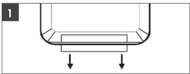
The remote control unit is delivered together with a lithium button cell 25. To enable the remote control, remove the plastic tape that protrudes from the battery compartment 23 (see Figure 1).
natural_image
Simple diagram of a U-shaped container with two downward arrows indicating flow or movement (no text or symbols)If the remote control battery needs to be replaced, insert a new 3-volt lithium button cell. Pay attention to the type of lithium button cell (CR2025).
- Press the tab 24 on the battery compartment 23 of the remote control toward the centre. Now pull out the battery compartment 23 (see Figure 2).
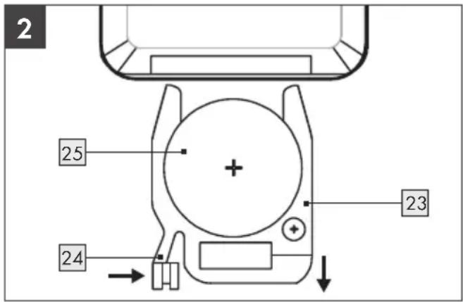
■ Remove the old battery 25.
- Insert a new 3V-button-cell battery (type CR2025). Pay attention to the correct polarity.
- Push the battery compartment 23 back into the remote control unit until the tab 24 snaps into place.
4. Starting Up
4.1 Standby mode
Plug the power cord 11 of the device into a wall outlet. The appliance is now supplied with power. A short signal tone sounds.
A circular movement is shown on the display 3 for approx. 20 seconds (charging process) when the device is started up.
Note: The display goes out. The device is now in standby mode and can be put into operation.
5. Control on the device
5.1 Switch on the device ⏻
Note: The buttons have a signal tone feedback. The white dot on the display signals active fan operation. The red dot signals active heating mode.
- Press the button ⏻1 to switch the product on. The appliance starts directly at ventilation level "003" when first used.
The next time it is used, the appliance starts at the same ventilation level that was selected during the last operation.
If the mains plug is disconnected in the meantime, the appliance restarts in ventilation level "003".
Note: During operation, the display 3 remains illuminated for approx. 20 seconds before the display goes out and switches to standby mode.
5.2 Switch off the device ⏻
■ To switch the device back to standby mode after operation, press the button ⏻ 1.
NOTE: The appliance switches off while the display 3 shows "000" for approx. 20 seconds and then also switches off.
5.3 Select operating mode Ⓜ
To change an operating mode, press the button M 8 repeatedly until the desired mode is shown on the display 3. You can choose between power, sleep, natural and ECO mode.
| -n- | Nature modeSimulation of natural gusts of wind.Every 10 seconds, the speed is reduced or increased by 4 levels of the set ventilation level.Note:The lowest adjustable speed in natural mode is therefore level 5 and the highest speed is level 16. |
| ECO | ECO modeOnly active in heating mode. Preset to 22 °C (the user cannot set the temperature).- If the room temperature is below 18 °C, the appliance operates at high speed- if the room temperature is between 18-22 °C, the appliance operates at low speed- if the room temperature is above 22 °C, the appliance operates at the lowest fan speed |
| Display | Operating mode |
| -P- | Power modeThe appliance switches to the highest level of ventilation mode |
| -S- | Sleep modeThe maximum speed in sleep mode is level 10. In sleep mode, the speed is reduced by 4 levels and increases by 2 levels after 10 seconds and again by 2 levels after a further 10 seconds. The set speed is thus reached again. This interval runs for 30 minutes. After this time, the appliance reduces the speed by 2 levels each time. This is repeated until level 2 is reached. |
Note: ECO mode can only be selected in heating mode. If you change the speed during an active operating mode, the operating mode is deactivated and must be reactivated.
5.4 Select ventilation levels
Press the button ⚙️ 9 repeatedly to reach the desired ventilation level.
- You can choose between 20 different ventilation levels.
■ The desired ventilation level is adopted directly.
5.5 Timer function
The timer is used to switch the appliance off automatically after a preset time. The timer function can be set for up to 12 hours.
During operation, press the button ⏻ 2 to access the timer function.
■Pressbutton 2 repeatedly to set the desired time. Starting with 15 - 30 - 45 minutes, as soon as the first hour is reached, the display jumps hour by hour.
015-030-045-01H-02H-03H-04H-05H-06H-07H-08H-09H-10H-11H-12H-000
- Wait approx. 10 seconds until the settings are applied.
■ After successful acceptance, the display returns to the current fan speed.
NOTE: A small dot flashes at the bottom right of the display 3, simulating the timer.
5.6 Oscillation function
- Press the oscillation button ⚙️ 7 to switch the oscillation of the appliance on or off.
- When successfully activated, the selected oscillation level is shown on the display 3.
You can choose between 4 levels from 30^ - 60^ - 90^ - 120^ .
The oscillation function ensures that the discharged air is distributed.
If the display is in standby mode, press the oscillation button ⚙️ 7 as much as the oscillation stops.
5.7 Select heating levels
- Press the button ⚙ 4 to switch to heating mode.
- Press the button repeatedly to increase the desired ventilation level.
- You can choose between 10 different ventilation levels.
5.8 Set temperature
Press the button ⏻ 5 to set the desired temperature. 25 °C is the preset temperature.
You can set the temperature from 5 °C - 35 °C.
The desired temperature setting is adopted directly.
Note: The heating is only activated if the set temperature is above the current room temperature. As soon as the room temperature falls below the set temperature, the appliance switches on automatically until the set temperature is reached again. In this way, the room temperature remains constant and power consumption is kept as low as possible.
Note: The default setting for the heating is 25 °C. If the room temperature falls below 0 °C, the LED display only shows --- as these cannot be displayed.
The appliance switches off automatically if it has been in continuous operation for 12 hours.
Note: The heater initially emits heat from the left-hand air outlet and after about 20 seconds emits heat from the right-hand side. This is a normal process.
■ After the appliance has been switched off from heating mode, it automatically switches to blower mode and blows out a stream of air for approx. 30 seconds to allow the heating element to cool down.
The 30-second countdown timer is displayed on the LED screen.
5.9 LED atmospheric light function
Press the button Ⓞ 6 to start the atmospheric light function.
- Press the ambience button repeatedly to set the desired color scheme (white, blue, green, red, purple).
- When you have reached the color purple, press the ambience button again to switch to the color change. The colors change automatically after a few seconds.
To end the atmospheric light function, press the ambience button again once the color change has been reached.
5.9.1 Setting the brightness of the LED atmospheric light
Press and hold the button ⚙ 6 for 1-2 seconds to adjust the brightness of the light.
Note: Up to 4 brightness levels can be set for each light color.
5.10 Frost monitor function
The appliance switches on automatically when the ambient temperature falls below 7 °C and switches off again above 10 °C ambient temperature.
6. Control with the remote control
6.1 Switch on the device ⏻
Note: The buttons have a signal tone feedback. The white dot on the display signals active fan operation. The red dot signals active heating mode.
Press the button ⏻12 to switch the product on. The appliance starts directly at ventilation level "003" when first used.
The next time it is used, the appliance starts at the same ventilation level that was selected during the last operation.
If the mains plug is disconnected in the meantime, the appliance restarts in ventilation level "003".
6.2 Switch off the device ⏻
To switch the appliance back to standby mode after operation, press the button ⏻12.
NOTE: The appliance switches off while the display 3 shows "000" for approx. 20 seconds and then also switches off.
6.3 Select operating mode Ⓜ
To change an operating mode, press the button M 22 repeatedly until the desired mode is shown on the display 3. You can choose between power, sleep, natural and ECO mode.
| Display | Operating mode |
| -P- | Power modeThe appliance switches to the highest level of ventilation mode |
| -S--n- | Sleep modeThe maximum speed in sleep mode is level 10. In sleep mode, the speed is reduced by 4 levels and increases by 2 levels after 10 seconds and again by 2 levels after a further 10 seconds. The set speed is thus reached again. This interval runs for 30 minutes. After this time, the appliance reduces the speed by 2 levels each time. This is repeated until level 2 is reached.Nature modeSimulation of natural gusts of wind.Every 10 seconds, the speed is reduced or increased by 4 levels of the set ventilation level.Note: The lowest adjustable speed in natural mode is therefore level 5 and the highest speed is level 16. |
| ECO | ECO modeOnly active in heating mode. Preset to 22 °C (the user cannot set the temperature).- If the room temperature is below 18 °C, the appliance operates at high speed- if the room temperature is between 18-22 °C, the appliance operates at low speed- if the room temperature is above 22 °C, the appliance operates at the lowest fan speed |
Note: ECO mode can only be selected in heating mode. If you change the speed during an active operating mode, the operating mode is deactivated and must be reactivated.
6.4 Select ventilation levels
■ To switch to fan mode, press the button 20.
Press the button + 15 repeatedly to increase the desired ventilation level.
■ Press the button —19 repeatedly to reduce the desired ventilation level.
- You can choose between 20 different ventilation levels.
■ The desired ventilation level is adopted directly.
6.5 Timer function
The timer is used to switch the appliance off automatically after a preset time. The timer function can be set for up to 12 hours.
Press the button ⏻ 13 during operation to access the timer function.
Press the button Ⓧ 13 repeatedly to set the desired time. Starting with 15 - 30 - 45 minutes, as soon as the first hour is reached, the display jumps hour by hour.
015-030-045-01H-02H-03H-04H-05H-06H-07H- 08H-09H-10H-11H-12H-000
- Wait approx. 10 seconds until the settings are applied.
■ After successful acceptance, the display returns to the current fan speed.
NOTE: A small dot flashes at the bottom right of the display 3 as long as the display is not in standby mode, which simulates the timer.
6.6 Oscillation function
Press the oscillation button ⚙ 14 to switch the oscillation of the appliance on or off.
When successfully activated, the selected oscillation level is shown on the display 3.
You can choose between 4 levels from 30^ - 60^ - 90^ - 120^ .
The oscillation function ensures that the discharged air is distributed.
If the display is in standby mode, press the oscillation button ⚙ 14 twice until the oscillation stops.
6.7 Select heating levels
Press the button 16 to switch to heating mode.
Press the button +15 or -19 repeatedly to set the desired ventilation level.
You can choose between 10 different ventilation levels.
Note: The heating is only activated if the set temperature is above the current room temperature.
6.8 Set temperature
Press the button 21, then use the button + 15 or - 19 to set the desired temperature. 25 °C is the preset temperature.
■ You can set the temperature from 5 °C - 35 °C.
The desired temperature setting is adopted directly.
Note: The heating is only activated if the set temperature is above the current room temperature. As soon as the room temperature falls below the set temperature, the appliance switches on automatically until the set temperature is reached again. In this way, the room temperature remains constant and power consumption is kept as low as possible.
Note: The default setting for the heating is 25 °C. If the room temperature falls below 0 °C, the LED display only shows --- as these cannot be displayed.
The appliance switches off automatically if it has been in continuous operation for 12 hours.
Note: The heater initially emits heat from the left-hand air outlet and after about 20 seconds emits heat from the right-hand side. This is a normal process.
■ After the appliance has been switched off from heating mode, it automatically switches to blower mode and blows out a stream of air for approx. 30 seconds to allow the heating element to cool down.
The 30-second countdown timer is displayed on the LED screen.
6.9 LED atmospheric light function
Press the button Ⓞ 17 to start the atmospheric light function.
- Press the ambience button repeatedly to set the desired color scheme (white, blue, green, red, purple).
- When you have reached the color purple, press the ambience button again to switch to the color change. The colors change automatically after a few seconds in the RGB color space.
To end the atmospheric light function, press the ambience button again once the color change has been reached.
6.9.1 Setting the brightness of the LED atmospheric light
Press the button ⏱ 18 to adjust the brightness of the light.
Note: Up to 4 brightness levels can be set for each light color.
- Troubleshooting
| Error code | Problem Possible cause(s) Solution | ||
| E1 Under voltage 1. Low/unstable power supply2. Incorrect input voltage (e.g. 110V) | 1. Check whether the power supply is stable and normal.2. Ensure the correct voltage (e.g. 220-240 V). | ||
| E2 | Overvoltage | 1. High/unstable power supply2. Incorrect voltage input (e.g. 260 V) | 1. Check whether the power supply is stable and normal.2. Ensure the correct voltage (e.g. 220-240 V). |
| E3 Fan wheel not turning | Faulty printed circuit board (PCB) | Check whether the problem has been resolved by unplugging the plug from the socket for about five minutes and then plugging it back in. | |
| E4 Hardware overcurrent | |||
| E5 Software overcurrent | |||
| E6 Motor error Motor without power supply If you receive an error message, please contact our customer services directly. | |||
| E7 Communication error | Defective cable connection between the printed circuit boards (PCBs). | Lidl-services@rowi-group.comService hotline: +800 7694 7694 | |
| E8 Tilt warning 1. Device tilts >30°2. Tilt switch/PCB malfunction | Place the device on a flat, stable surface and check the tip-over protection. | ||
| E9 Faulty temperature sensor | 1. Temperature sensor cable disconnected/loose.2. Sensor needs recalibration.3. Signal interference of the printed circuit board (PCB) | If you receive an error message, please contact our customer services directly.Lidl-services@rowi-group.comService hotline: +800 7694 7694 | |
Note: If the suggested solutions do not work, please contact our service hotline (chapter 11) for further assistance.
8. Maintenance, cleaning and storage
■ Always disconnect the mains plug when the appliance is not in use and before cleaning or in the event of malfunctions!
- Only clean the appliance when it is switched off and cold.
■ Make sure that no moisture enters the appliance during cleaning to avoid irreparable damage to the appliance.
Only clean the housing with a dry, soft cloth. Never use abrasive and/or scratchy cleaning agents.
■ Remove dust deposits from the appliance with a vacuum cleaner.
■ Store the device in a dry environment.
9. Disposal
The packaging is made of environmentally friendly materials that you can dispose of at your local recycling centres.
These logos are only valid for Spain.


The Triman logo is valid in France only.
This product is subject to the European Directive 2012/19/EU. Do not dispose of the product in household waste, but via municipal collection points for material recycling! Further information on how to dispose of the discarded device can be obtained from your local authority or city council.

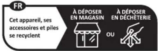
Batteries must be recycled in accordance with Directive 2006/66/EC and may not be disposed of with domestic waste. Each consumer is legally obliged to return all batteries/rechargeable batteries to a collection point in his municipality/district or to the trade. This duty serves to ensure that batteries/rechargeable batteries can be directed to environmentally friendly disposal. Only return batteries/rechargeable batteries which are not charged. Batteries must be removed from the appliance prior to disposal.
Observe the labelling of the packaging materials when separating waste; these are marked with abbreviations (a) and numbers (b) with the following meaning: 1-7: Plastics/20-22: Paper and cardboard/80-98: Composites.
10. Resource efficiency
Your product has been designed to be durable and easy to maintain. To extend the life of your product, certain replacement parts are available after purchase.
10.1 Availability and maximum delivery times for spare parts
Details on spare part availability can be found on our website:
https://rowi-group.com/produktinformationen/
PartsInfo_IAN_487583.pdf
or obtained directly from our service hotline.
Lidl-services@rowi-group.com
Service-Hotline: +800 7694 7694
(free call from a German landline)
NOTE: Please note that replacement parts should only be installed by trained specialists. Repairs carried out by yourself will void the warranty and result in significant safety risks.
11. ROWI Germany GmbH Warranty
Dear Customer,
This appliance has a 3-year warranty valid from the date of purchase. If this product has any faults, you, the buyer, have certain statutory rights. Your statutory rights are not restricted in any way by the warranty described below.
Warranty conditions
The validity period of the warranty starts from the date of purchase. Please keep your original receipt in a safe place. This document will be required as proof of purchase.
If any material or production fault occurs within three years of the date of purchase of the product, we will either repair or replace the product for you or refund the purchase price at our discretion. This warranty service is dependent on you presenting the defective appliance and the proof of purchase (receipt) and a short written description of the fault and its time of occurrence.
If the defect is covered by the warranty, your product will either be repaired or replaced by us. The repair or replacement of a product does not signify the beginning of a new warranty period.
Warranty period and statutory claims for defects
The warranty period is not prolonged by repairs effected under the warranty. This also applies to replaced and repaired components. Any damage and defects present at the time of purchase must be reported immediately after unpacking. Repairs carried out after expiry of the warranty period shall be subject to a fee.
Scope of the warranty
This appliance has been manufactured in accordance with strict quality guidelines and inspected meticulously prior to delivery.
The warranty covers material faults or production faults. The warranty does not extend to product parts subject to normal wear and tear or fragile parts such as switches, batteries or those made of glass.
The warranty does not apply if the product has been damaged, improperly used or improperly maintained. The directions in the operating instructions for the product regarding proper use of the product are to be strictly followed. Uses and actions that are discouraged in the operating instructions or which are warned against must be avoided.
This product is intended solely for private use and not for commercial purposes. The warranty shall be deemed void in cases of misuse or improper handling, use of force and modifications/repairs which have not been carried out by one of our authorised Service centres.
Warranty claim procedure
To ensure quick processing of your case, please observe the following instructions:
Please have the till receipt and the item number (IAN 487583_2501) available as proof of purchase.
- You will find the item number on the type plate on the product, on the front page of the instructions (bottom left), or as a sticker on the rear or bottom of the appliance.
If functional or other defects occur, please contact the service department listed either by telephone or by e-mail.
- You can return a defective product to us free of charge to the service address that will be provided to you. Ensure that you enclose the proof of purchase (till receipt) and information about what the defect is and when it occurred.

At www.lidl-service.com you can download this manual as well as many other manuals, product videos and installation software. This QR code will take you directly to the Lidl service page (www.lidl-service.com) and allow you to open your operating instructions simply by entering the article number (IAN 487583_2501).
12. Service
If any problems occur during use of your ROWI Germany product, please proceed as follows:
Contact us
You can contact the service team of ROWI Germany at:
ROWI Germany GmbH
(free call from a German landline)
IAN 487583_2501
Most problems can be resolved with the skilled technical support of our Service Team.
1. Einleitung 27
natural_image
Simple diagram of a container with two downward arrows indicating flow or movement (no text or symbols)TianQiu Industrial Park, Xinji Industrial Zone, Machong Town, Dongguan, GuangDong, P.R. China
Tel: 0086-769-81210216
Email : gd@gdtiangiu.com
Site web: http://www.tmmq.cn
natural_image
Simple diagram of a container with two downward arrows indicating flow or movement (no text or symbols)WAARSCHUWING! Niet afdekken!
natural_image
Simple diagram of a container with two downward arrows indicating flow or movement (no text or symbols)natural_image
Simple diagram of a container with two downward arrows indicating flow or movement (no text or symbols)TianQiu Industrial Park, Xinji Industrial Zone, Machong Town, Dongguan, GuangDong, P.R. China Tel: 0086-769-81210216
E-mail: gd@gdtiangiu.com
Witryna: http://www.tmmq.cn
natural_image
Simple diagram of a container with two downward arrows indicating flow or movement (no text or symbols)natural_image
Simple diagram of a U-shaped container with two downward arrows indicating flow or movement (no text or symbols)natural_image
Simple diagram of a U-shaped container with two downward arrows indicating flow or movement (no text or symbols)natural_image
Simple diagram of a container with two downward arrows indicating flow or movement (no text or symbols)TianQiu Industrial Park, Xinji Industrial Zone,
Machong Town, Dongguan, GuangDong, P.R. China
Tel: 0086-769-81210216
Email: gd@gdtiangiu.com
Sito web: http://www.tmmq.cn
natural_image
Simple diagram of a container with two downward arrows indicating flow or movement (no text or symbols)natural_image
Simple diagram of a container with two downward arrows indicating flow or movement (no text or symbols)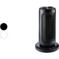
- FAN HEATER TRHV 2000 A1 HEIZVENTILATOR TRHV 2000 A1 VENTILATEUR-CHAUFFAGE TRHV 2000 A1
- FAN HEATER
- VENTILATEUR-CHAUFFAGE
- Introduction 7
- Safety indications 10
- Before you start the device 14
- Starting Up 14
- Control on the device 14
- Control with the remote control ...17.
- Troubleshooting 20
- Maintenance, cleaning and storage 21
- Disposal 21
- Resource efficiency 21
- ROWI Germany GmbH Warranty 22
- Service 23
- FAN HEATER TRHV 2000 A1
- Introduction
- Intended Use
- Scope of Delivery
- Equipment
- Fan
- Remote control
- Technical Data
- Remote control (only for use with Fan heater TRHV 2000 A1)
- Battery manufacturer
- Information requirements for electric local space heaters
- Type of heat output/room temperature control (select one)
- Other control options (multiple selections possible)
- Safety indications
- Read all the safety indications and instructions.
- General safety indications:
- Safety of electrical appliances for home use
- Specific safety indications:
- Special requirements for room heating appliances
- WARNING! Do not cover!
- Warning against hot surfaces!
- Danger to life due to electrical current!
- Information about batteries
- Keep out of reach of children.
- Before you start the device
- Device Installation
- Remote control: How to insert or change the battery
- Starting Up
- Standby mode
- Control on the device
- Switch on the device ⏻
- Switch off the device ⏻
- Select operating mode Ⓜ
- Select ventilation levels
- Timer function
- Oscillation function
- Select heating levels
- Set temperature
- LED atmospheric light function
- Setting the brightness of the LED atmospheric light
- Frost monitor function
- Control with the remote control
- Switch on the device ⏻
- Switch off the device ⏻
- Select operating mode Ⓜ
- Select ventilation levels
- Timer function
- Oscillation function
- Select heating levels
- Set temperature
- LED atmospheric light function
- Setting the brightness of the LED atmospheric light
- Maintenance, cleaning and storage
- Disposal
- Resource efficiency
- Availability and maximum delivery times for spare parts
- ROWI Germany GmbH Warranty
- Warranty conditions
- Warranty period and statutory claims for defects
- Scope of the warranty
- Warranty claim procedure
- Service
- Contact us
- Einleitung 27
- WAARSCHUWING! Niet afdekken!
Brand : TRONIC
Model : TRHV 2000 A1
Category : Electric heating