
GTS 18V-70 Professional - Saw BOSCH - Free user manual and instructions
Find the device manual for free GTS 18V-70 Professional BOSCH in PDF.

| Product Type | Cordless Table Saw |
| Brand / Model | Bosch GTS 18V-70 Professional |
| Dimensions (L × W × H) | 593 × 608 × 329 mm |
| Weight (without battery) | 21.2 kg |
| Power Supply | 18 V lithium-ion battery (compatible with GBA 18V, ProCORE18V, etc.) |
| No-Load Speed | 5500 rpm |
| Max. Cutting Height | 70 mm (cut at 0°), 49 mm (cut at 45°) |
| Blade Diameter | 216 mm |
| Arbor Size | 30 mm or 25.4 mm depending on version |
| Max. Blade Body Thickness | < 1.7 mm (ref. 3 601 M44 1..) / < 2.1 mm (ref. 3 601 M44 1B.) |
| Min. Cutting Width | > 1.9 mm / > 2.3 mm |
| Riving Knife Thickness | 1.8 mm / 2.2 mm |
| Bevel Angle Range | -2° to 47° (vertical), -30° to +30° horizontally (miters) |
| Main Functions | Rip cuts, cross cuts, miter cuts, bevel cuts, grooving (with appropriate guard) |
| Safety | Adjustable riving knife, blade guard, anti-kickback pawls, push stick, emergency stop, overload and restart protection |
| Maintenance and Cleaning | Regular cleaning of ventilation slots, chips and dust; lubrication at indicated points; use sharp blades |
| Spare Parts and Repairability | Spare parts via Bosch service center; maintenance by qualified repairer |
| General Information | Compliant with EN 62841-3-1; sound level 88 dB(A) / 100 dB(A); operating temperature -20 to +50 °C |
Frequently Asked Questions - GTS 18V-70 Professional BOSCH
User questions about GTS 18V-70 Professional BOSCH
0 question about this device. Answer the ones you know or ask your own.
Ask a new question about this device
Download the instructions for your Saw in PDF format for free! Find your manual GTS 18V-70 Professional - BOSCH and take your electronic device back in hand. On this page are published all the documents necessary for the use of your device. GTS 18V-70 Professional by BOSCH.
USER MANUAL GTS 18V-70 Professional BOSCH
natural_image
3D rendering of a mechanical assembly with no visible text or symbolsEnglish ...... Page 36
Français......Page 51
8
1 609 92A A8V | (11.04.2025) Bosch Power Tools
natural_image
Mechanical assembly diagram showing a machine with levers and components mounted on a table (no text or symbols visible)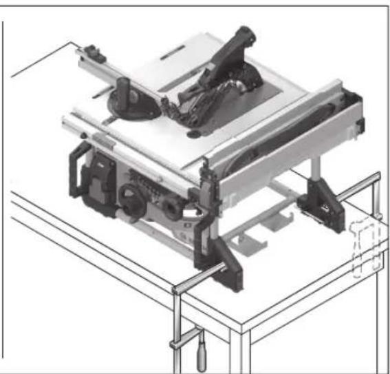
natural_image
Technical line drawing of a mechanical assembly with no visible text or symbols10
g
natural_image
Two technical diagrams of a mechanical device with articulated legs and a flat base, labeled 'GTA 571' (no text or symbols on the devices themselves)h
i
(40)
(3)
(5) (22)
(6)
(50)
(39)
(52)
(51) (22)
(27)
(54)
(53)
(55)
(51)
12
Bosch Power Tools 1 609 92A A8V | (11.04.2025)
14
natural_image
Mechanical assembly diagram showing a component with labeled parts (14), no readable text or symbols beyond label and number G3 marker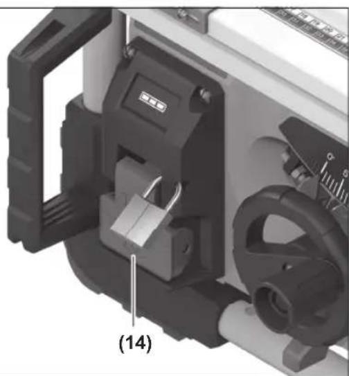
natural_image
Close-up of a mechanical device with internal components and a labeled part (14), no readable text or symbols present.| 15
Bosch Power Tools 1 609 92A A8V | (11.04.2025)
16
Bosch Power Tools 1 609 92A A8V | (11.04.2025)
18
Q

natural_image
Mechanical assembly diagram showing a motor and housing component (no text or symbols visible)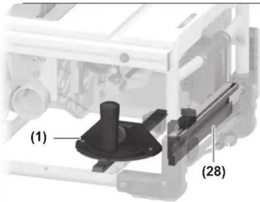
natural_image
Mechanical assembly diagram showing a bracket with mounting feet and a labeled component (22), no readable text or symbols present.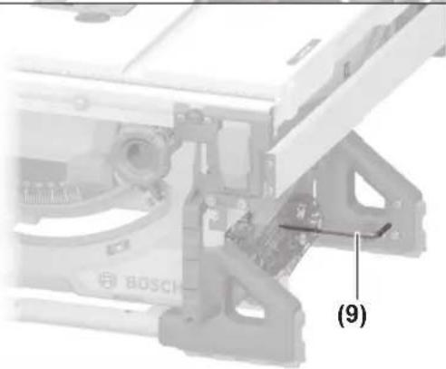
natural_image
Mechanical assembly diagram showing a Bosch component with labeled parts (9), no readable text or symbols beyond the label.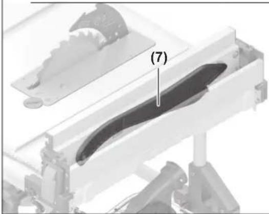
natural_image
Mechanical assembly diagram showing a curved mechanical component with labeled part (7), no readable text or symbols present.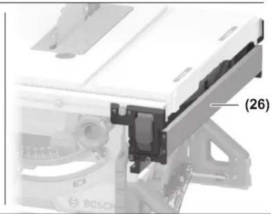
natural_image
Close-up of a mechanical assembly with labeled component (26), no readable text or symbols beyond label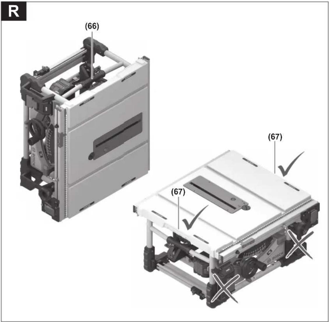
natural_image
Mechanical assembly diagram showing internal components and directional arrows (no text or labels)Bosch Power Tools 1 609 92A A8V | (11.04.2025)
Deutsch
Sicherheitshinweise
General Power Tool Safety Warnings
WARNING
Read all safety warnings, instructions, illustrations and specifica-
tions provided with this power tool. Failure to follow all instructions listed below may result in electric shock, fire and/or serious injury.
Save all warnings and instructions for future reference.
The term "power tool" in the warnings refers to your mains-operated (corded) power tool or battery-operated (cordless) power tool.
Work area safety
▶ Keep work area clean and well lit. Cluttered or dark areas invite accidents.
▶ Do not operate power tools in explosive atmospheres, such as in the presence of flammable liquids, gases or dust. Power tools create sparks which may ignite the dust or fumes.
▶ Keep children and bystanders away while operating a power tool. Distractions can cause you to lose control.
Electrical safety
▶ Power tool plugs must match the outlet. Never modify the plug in any way. Do not use any adapter plugs with earthed (grounded) power tools. Unmodified plugs and matching outlets will reduce risk of electric shock.
▶ Avoid body contact with earthed or grounded surfaces, such as pipes, radiators, ranges and refrigerators. There is an increased risk of electric shock if your body is earthed or grounded.
▶ Do not expose power tools to rain or wet conditions. Water entering a power tool will increase the risk of electric shock.
▶ Do not abuse the cord. Never use the cord for carrying, pulling or unplugging the power tool. Keep cord away from heat, oil, sharp edges or moving parts. Damaged or entangled cords increase the risk of electric shock.
▶ When operating a power tool outdoors, use an extension cord suitable for outdoor use. Use of a cord suitable for outdoor use reduces the risk of electric shock.
▶ If operating a power tool in a damp location is unavoidable, use a residual current device (RCD) protected supply. Use of an RCD reduces the risk of electric shock.
Personal safety
▶ Stay alert, watch what you are doing and use common sense when operating a power tool. Do not use a power tool while you are tired or under the influence of drugs, alcohol or medication. A moment of inattention while operating power tools may result in serious personal injury.
▶ Use personal protective equipment. Always wear eye protection. Protective equipment such as a dust mask, non-skid safety shoes, hard hat or hearing protection used for appropriate conditions will reduce personal injuries.
▶ Prevent unintentional starting. Ensure the switch is in the off-position before connecting to power source and/or battery pack, picking up or carrying the tool.
Carrying power tools with your finger on the switch or energising power tools that have the switch on invites accidents.
Remove any adjusting key or wrench before turning the power tool on. A wrench or a key left attached to a rotating part of the power tool may result in personal injury.
▶ Do not overreach. Keep proper footing and balance at all times. This enables better control of the power tool in unexpected situations.
▶ Dress properly. Do not wear loose clothing or jewellery. Keep your hair and clothing away from moving parts. Loose clothes, jewellery or long hair can be caught in moving parts.
If devices are provided for the connection of dust extraction and collection facilities, ensure these are connected and properly used. Use of dust collection can reduce dust-related hazards.
▶ Do not let familiarity gained from frequent use of tools allow you to become complacent and ignore tool safety principles. A careless action can cause severe injury within a fraction of a second.
Power tool use and care
▶ Do not force the power tool. Use the correct power tool for your application. The correct power tool will do the job better and safer at the rate for which it was designed.
▶ Do not use the power tool if the switch does not turn it on and off. Any power tool that cannot be controlled with the switch is dangerous and must be repaired.
▶ Disconnect the plug from the power source and/or remove the battery pack, if detachable, from the power tool before making any adjustments, changing accessories, or storing power tools. Such preventive safety measures reduce the risk of starting the power tool accidentally.
▶ Store idle power tools out of the reach of children and do not allow persons unfamiliar with the power tool or these instructions to operate the power tool. Power tools are dangerous in the hands of untrained users.
- Maintain power tools and accessories. Check for misalignment or binding of moving parts, breakage of parts and any other condition that may affect the power tool's operation. If damaged, have the power tool repaired before use. Many accidents are caused by poorly maintained power tools.
▶ Keep cutting tools sharp and clean. Properly maintained cutting tools with sharp cutting edges are less likely to bind and are easier to control.
▶ Use the power tool, accessories and tool bits etc. in accordance with these instructions, taking into account the working conditions and the work to be performed. Use of the power tool for operations different from those intended could result in a hazardous situation.
▶ Keep handles and grasping surfaces dry, clean and free from oil and grease. Slippery handles and grasping surfaces do not allow for safe handling and control of the tool in unexpected situations.
Battery tool use and care
▶ Recharge only with the charger specified by the manufacturer. A charger that is suitable for one type of bat-
38 | English
tery pack may create a risk of fire when used with another battery pack.
▶ Use power tools only with specifically designated battery packs. Use of any other battery packs may create a risk of injury and fire.
When battery pack is not in use, keep it away from other metal objects, like paper clips, coins, keys, nails, screws or other small metal objects, that can make a connection from one terminal to another. Shorting the battery terminals together may cause burns or a fire.
▶ Under abusive conditions, liquid may be ejected from the battery; avoid contact. If contact accidentally occurs, flush with water. If liquid contacts eyes, additionally seek medical help. Liquid ejected from the battery may cause irritation or burns.
▶ Do not use a battery pack or tool that is damaged or modified. Damaged or modified batteries may exhibit unpredictable behaviour resulting in fire, explosion or risk of injury.
▶ Do not expose a battery pack or tool to fire or excessive temperature. Exposure to fire or temperature above 130°C may cause explosion.
▶ Follow all charging instructions and do not charge the battery pack or tool outside the temperature range specified in the instructions. Charging improperly or at temperatures outside the specified range may damage the battery and increase the risk of fire.
Service
▶ Have your power tool serviced by a qualified repair person using only identical replacement parts. This will ensure that the safety of the power tool is maintained.
▶ Never service damaged battery packs. Service of battery packs should only be performed by the manufacturer or authorized service providers.
Safety instructions for table saws
Guarding related warnings
▶ Keep guards in place. Guards must be in working order and be properly mounted. A guard that is loose, damaged, or is not functioning correctly must be repaired or replaced.
▶ Always use saw blade guard and riving knife for every through-cutting operation. For through-cutting operations where the saw blade cuts completely through the thickness of the workpiece, the guard and other safety devices help reduce the risk of injury.
▶ After completing a non-through cut such as rabbeting, restore the riving knife to the extended-up position. With the riving knife in the extended-up position, reattach the blade guard. The guard and riving knife help to reduce the risk of injury.
▶ Make sure the saw blade is not contacting the guard, riving knife or the workpiece before the switch is turned on. Inadvertent contact of these items with the saw blade could cause a hazardous condition.
▶ Adjust the riving knife as described in this instruction manual. Incorrect spacing, positioning and alignment can make the riving knife ineffective in reducing the likelihood of kickback.
For the riving knife to work, it must be engaged in the workpiece. The riving knife is ineffective when cutting workpieces that are too short to be engaged with the riving knife. Under these conditions, a kickback cannot be prevented by the riving knife.
▶ Use the appropriate saw blade for the riving knife. For the riving knife to function properly, the saw blade diameter must match the appropriate riving knife and the body of the saw blade must be thinner than the thickness of the riving knife and the cutting width of the saw blade must be wider than the thickness of the riving knife.
Cutting procedures warnings
▶ HANGER: Never place your fingers or hands in the vicinity or in line with the saw blade. A moment of inattention or a slip could direct your hand towards the saw blade and result in serious personal injury.
▶ Feed the workpiece into the saw blade only against the direction of rotation. Feeding the workpiece in the same direction that the saw blade is rotating above the table may result in the workpiece, and your hand, being pulled into the saw blade.
▶ Never use the mitre gauge to feed the workpiece when ripping and do not use the rip fence as a length stop when cross cutting with the mitre gauge. Guiding the workpiece with the rip fence and the mitre gauge at the same time increases the likelihood of saw blade binding and kickback.
When ripping, always keep the workpiece in full contact with the fence and always apply the workpiece feeding force between the fence and the saw blade. Use a push stick when the distance between the fence and the saw blade is less than 150 mm, and use a push block when this distance is less than 50 mm. "Work helping" devices will keep your hand at a safe distance from the saw blade.
▶ Use only the push stick provided by the manufacturer or constructed in accordance with the instructions. This push stick provides sufficient distance of the hand from the saw blade.
▶ Never use a damaged or cut push stick. A damaged or cut push stick may break causing your hand to slip into the saw blade.
Do not perform any operation "freehand". Always use either the rip fence or the mitre gauge to position and guide the workpiece. "Freehand" means using your hands to support or guide the workpiece, in lieu of a rip fence or mitre gauge. Freehand sawing leads to misalignment, binding and kickback.
▶ Never reach around or over a rotating saw blade. Reaching for a workpiece may lead to accidental contact with the moving saw blade.
▶ Provide auxiliary workpiece support to the rear and/or sides of the saw table for long and/or wide workpieces to keep them level. A long and/or wide workpiece has a tendency to pivot on the table's edge, causing loss of control, saw blade binding and kickback.
▶ Feed the workpiece at an even pace. Do not bend, twist or shift the workpiece from side to side. If jamming occurs, turn the tool off immediately, unplug the tool, then clear the jam. Jamming the saw blade by the workpiece can cause kickback or stall the motor.
▶ Do not remove pieces of cut-off material while the saw is running. The material may become trapped between the fence or inside the saw blade guard and the saw blade pulling your fingers into the saw blade. Turn the saw off and wait until the saw blade stops before removing material.
▶ Use an auxiliary fence in contact with the table top when ripping workpieces less than 2 mm thick. A thin workpiece may wedge under the rip fence and create a kickback.
Kickback causes and related warnings
Kickback is a sudden reaction of the workpiece due to a pinched, jammed saw blade or misaligned line of cut in the workpiece with respect to the saw blade or when a part of the workpiece binds between the saw blade and the rip fence or other fixed object.
Most frequently during kickback, the workpiece is lifted from the table by the rear portion of the saw blade and is propelled towards the operator.
Kickback is the result of saw misuse and/or incorrect operating procedures or conditions and can be avoided by taking proper precautions as given below.
▶ Never stand directly in line with the saw blade. Always position your body on the same side of the saw blade as the fence. Kickback may propel the workpiece at high velocity towards anyone standing in front and in line with the saw blade.
▶ Never reach over or in back of the saw blade to pull or to support the workpiece. Accidental contact with the saw blade may occur or kickback may drag your fingers into the saw blade.
▶ Never hold and press the workpiece that is being cut off against the rotating saw blade. Pressing the workpiece being cut off against the saw blade will create a binding condition and kickback.
Align the fence to be parallel with the saw blade. A misaligned fence will pinch the workpiece against the saw blade and create kickback.
▶ Use a featherboard to guide the workpiece against the table and fence when making non-through cuts such as rabbeting. A featherboard helps to control the workpiece in the event of a kickback.
▶ Support large panels to minimise the risk of saw blade pinching and kickback. Large panels tend to sag under their own weight. Support(s) must be placed under all portions of the panel overhanging the table top.
▶ Use extra caution when cutting a workpiece that is twisted, knotted, warped or does not have a straight edge to guide it with a mitre gauge or along the fence. A warped, knotted, or twisted workpiece is unstable and causes misalignment of the kerf with the saw blade, binding and kickback.
▶ Never cut more than one workpiece, stacked vertically or horizontally. The saw blade could pick up one or more pieces and cause kickback.
When restarting the saw with the saw blade in the workpiece, centre the saw blade in the kerf so that the saw teeth are not engaged in the material. If the saw blade binds, it may lift up the workpiece and cause kick-back when the saw is restarted.
▶ Keep saw blades clean, sharp, and with sufficient set. Never use warped saw blades or saw blades with cracked or broken teeth. Sharp and properly set saw blades minimise binding, stalling and kickback.
Table saw operating procedure warnings
▶ Turn off the table saw and disconnect the battery pack when removing the table insert, changing the saw blade or making adjustments to the riving knife or blade guard, and when the machine is left unattended. Precautionary measures will avoid accidents.
▶ Never leave the table saw running unattended. Turn it off and don't leave the tool until it comes to a complete stop. An unattended running saw is an uncontrolled hazard.
▶ Locate the table saw in a well-lit and level area where you can maintain good footing and balance. It should be installed in an area that provides enough room to easily handle the size of your workpiece. Cramped, dark areas, and uneven slippery floors invite accidents.
▶ Frequently clean and remove sawdust from under the saw table and/or the dust collection device. Accumulated sawdust is combustible and may self-ignite.
The table saw must be secured. A table saw that is not properly secured may move or tip over.
▶ Remove tools, wood scraps, etc. from the table before the table saw is turned on. Distraction or a potential jam can be dangerous.
▶ Always use saw blades with correct size and shape (diamond versus round) of arbour holes. Saw blades that do not match the mounting hardware of the saw will run off-centre, causing loss of control.
▶ Never use damaged or incorrect saw blade mounting means such as flanges, saw blade washers, bolts or nuts. These mounting means were specially designed for your saw, for safe operation and optimum performance.
▶ Never stand on the table saw, do not use it as a stepping stool. Serious injury could occur if the tool is tipped or if the cutting tool is accidentally contacted.
▶ Make sure that the saw blade is installed to rotate in the proper direction. Do not use grinding wheels, wire brushes, or abrasive wheels on a table saw. Improper
40 | English
saw blade installation or use of accessories not recommended may cause serious injury.
Additional safety warnings
▶ When mounting the saw blade, wear protective gloves. This poses a risk of injury.
▶ Do not use HSS saw blades. Such saw blades can easily break.
▶ Only use saw blades that match the specifications given in this operating manual and that are tested and marked in accordance with EN 847-1
▶ Never use the tool without the table insert. Replace table insert if defective. Without flawless table inserts, injuries are possible from the saw blade.
▶ Keep your work area clean. Material mixtures are particularly hazardous. Light metal dust may catch fire or explode.
▶ Choose the saw blade suited to the material you want to work on.
▶ Only use saw blades that are recommended by the power tool manufacturer and are suitable for using on the material you want to saw.
▶ Only advance the workpiece towards the saw blade when it is running. Otherwise there is a risk of kickback occurring if the saw blade catches in the workpiece.
In case of damage and improper use of the battery, vapours may be emitted. The battery can set alight or explode. Ensure the area is well ventilated and seek medical attention should you experience any adverse effects. The vapours may irritate the respiratory system.
▶ Do not modify or open the battery. There is a risk of short-circuiting.
The battery can be damaged by pointed objects such as nails or screwdrivers or by force applied externally. An internal short circuit may occur, causing the battery to burn, smoke, explode or overheat.
▶ Only use the battery in the manufacturer's products. This is the only way in which you can protect the battery against dangerous overload.
Protect the battery against heat, e.g. against continuous intense sunlight, fire, dirt, water and moisture. There is a risk of explosion and short-circuiting.
Symbols
The following symbols may be important for the operation of your power tool. Please take note of these symbols and their meaning. Correctly interpreting the symbols will help you to operate the power tool more effectively and safely.
Symbols and their meaning

Keep hands away from the cutting area while the power tool is running. Contact with the saw blade can lead to injuries.

Wear a dust mask.

Wear hearing protection. Exposure to noise can cause hearing loss.

Wear safety goggles.
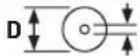
d Take note of the dimensions of the saw blade (saw blade diameter D, hole diameter d). The hole diameter d must match the tool spindle without play. If it is necessary to use reducers, ensure that the dimensions of the reducer are suitable for the base blade thickness and the saw blade hole diameter, as well as the tool spindle diameter. Wherever possible, use the reducers provided with the saw blade.
The saw blade diameter D must match the information specified on the symbol.
See also: "Dimensions of suitable saw blades" in the "Technical Data" section.
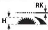
Note the thickness of the riving knife RK and the maximum possible workpiece height H.
See also the "Technical Data" section.
Take note of the information on the riving knife when changing the saw blade. Otherwise, there is a risk that the riving knife will hook into the workpiece.
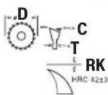
D Diameter of the saw blade
C Minimum cutting width (tooth thickness/offset)
T Maximum base blade thickness

RK Riving knife thickness
ROTATION The cutting direction of the teeth (direction of the arrow on the saw blade) must match the direction of the arrow on the riving knife
Symbols and their meaning
See also the "Technical Data" section.
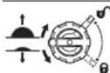
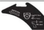
Left-hand side:
Indicates the direction of rotation of the crank for lowering (transport position) and raising (work position) the saw blade.
Right-hand side:
Indicates the position of the locking lever for securing the saw blade and setting the bevel angle (saw blade can be swivelled).

Rotational direction for securing/undoing the table insert
Do not touch the saw blade with the push stick.
CLAMPZONE
Clamps can be attached to the saw table in this area.

The CE mark provides confirmation from the manufacturer that the power tool complies with the applicable EU Directives.
Product Description and Specifications

Read all the safety and general instructions.
Failure to observe the safety and general instructions may result in electric shock, fire and/or serious injury.
Please observe the illustrations at the beginning of this operating manual.
Intended use
The power tool is a stationary machine for cutting in a straight line with and against the grain in hardwood, softwood, chipboard and fibreboard. Mitre angles of -30^ to +30^ as well as bevel angles of -2^ to 47^ are possible. It is also possible to saw aluminium profiles and plastic using the appropriate saw blades.
Product features
The numbering of the product features refers to the diagram of the power tool on the graphics page.
(1) Angle guide
(2) Saw table
(3) Protective cover
(4) Dust extraction adapter on protective cover
(5) Riving knife
(6) Table insert
(7) Push stick
(8) Additional parallel guide (folding)
(9) Hex key (5 mm/2.5 mm)
(10) Bracket for storing the protective cover
(11) Positioning handle for aligning the power tool (no carrying handle)
(12) Assembly holes
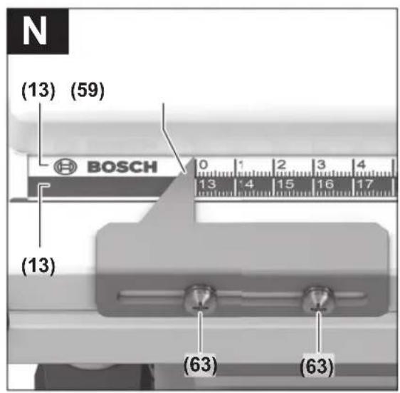
(13) Scale for spacing between saw blade and parallel guide
(14) On/off switch
(15) Battery charge indicator on the power tool
(16) Stop for 0^ bevel angle
(17) Mitre/bevel angle handwheel
(18) Locking lever for setting the bevel angle
(19) Crank for raising and lowering the saw blade
(20) Scale for bevel angle
(21) Stop for 45° bevel angle (vertical)
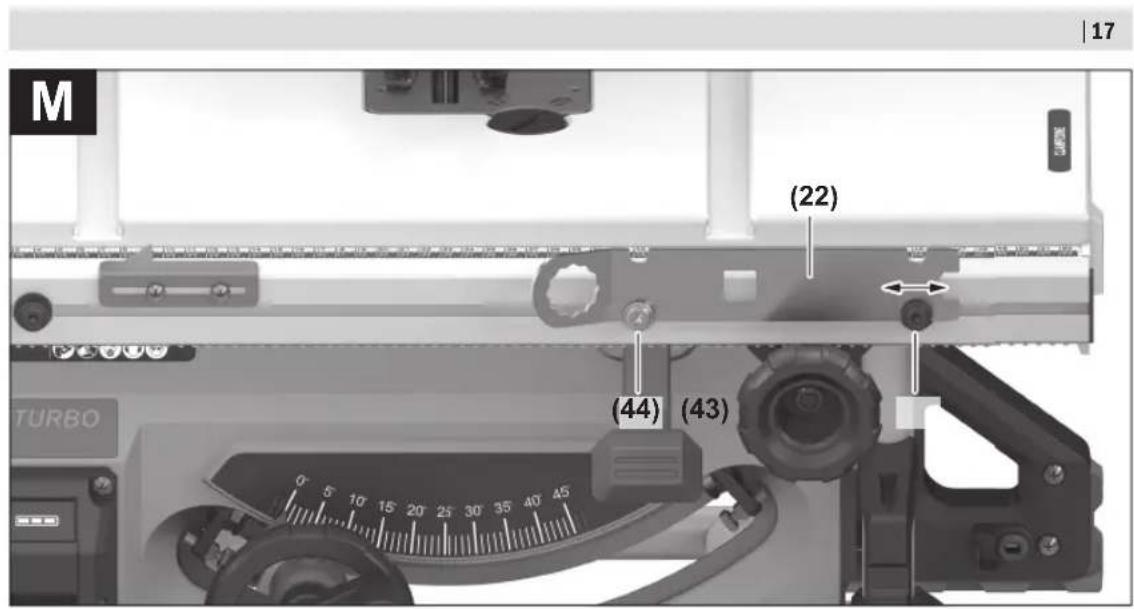
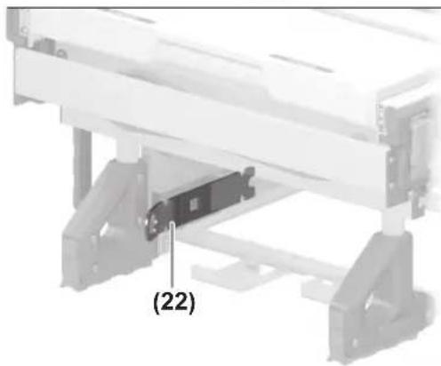
(22) Ring spanner
(23) Rotary knob for parallel guide
(24) Clamping handle for saw table expansion
(25) Guide rail for parallel guide
(26) Parallel guide
(27) Saw blade
(28) Profile rail
(29) Length stop for wing bolt
(30) Length stop
(31) Battery release button ^a)
(32) Rechargeable battery ^a)
(33) Bracket for storing the angle guide
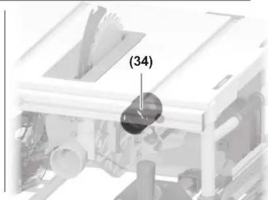
(34) Dust extraction adapter
(35) Chip ejector
(36) Clamping lever for riving knife
(37) Positioning pins for riving knife
(38) Clamping lever/clamping plate markings
(39) Locking screw for table insert
(40) Clamping lever for protective cover
(41) Guide pins for protective cover
(42) Locking levers for parallel guide
(43) Pair of pins (right, black)
(44) Pair of pins (right, silver)
(45) Pair of pins (left, black)
(46) Angle guide for the guide rail
(47) Guide groove for angle guide
(48) Knurled screw for profile rail
(49) Cover cap for chip ejector
42 | English
| (50) | Gripping hole for lifting the table insert | (60) | Screw for bevel angle indicator (vertical) |
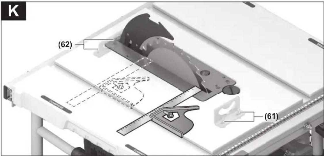
| (51) | Clamping nut | (61) | Hex socket screws (5 mm) on the front for adjusting the parallelism of the saw blade |
| (52) | Spindle locking lever | ||
| (53) | Clamping flange | (62) | Hex socket screws (5 mm) on the rear for adjusting the parallelism of the saw blade |
| (54) | Mounting flange | ||
| (55) | Tool spindle | (63) | Screw for saw table spacing indicator |
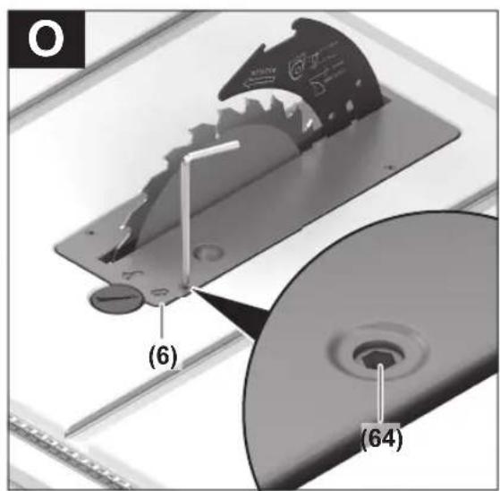
| (56) | Angle indicator (vertical) | (64) | Adjusting screws for insert plate |
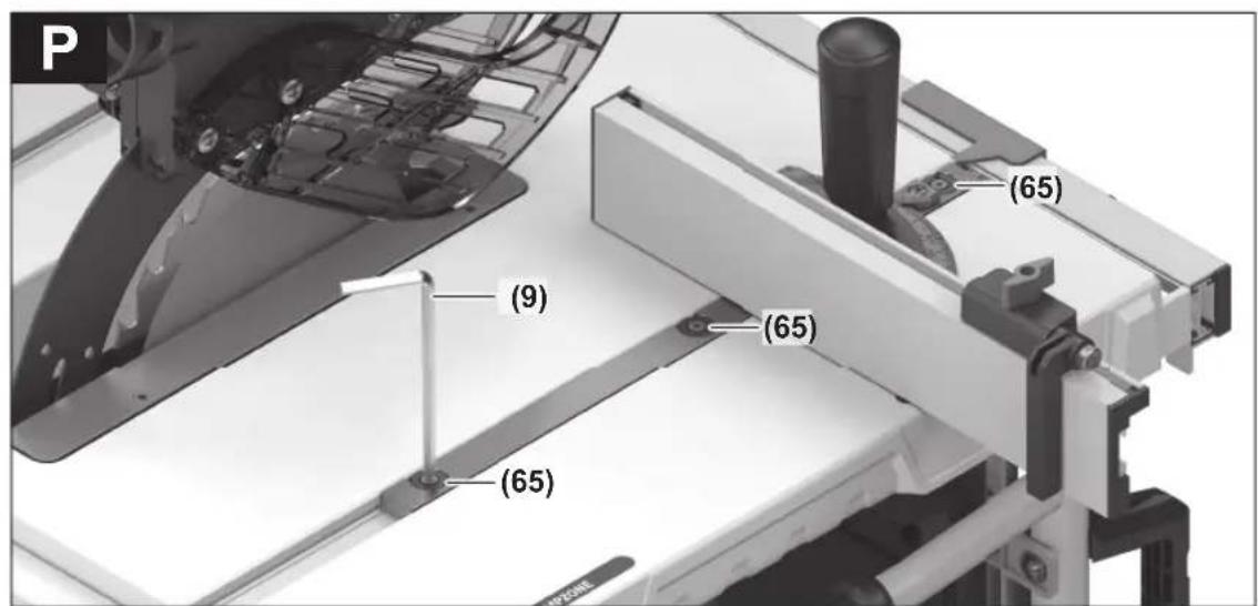
| (57) | Locking knob for all mitre angles (horizontal) | (65) | Setscrews for guide rail angle guide |
| (58) | Mitre angle indicator on the angle guide | (66) | Carrying handle |
| (59) | Spacing indicator | (67) | Recessed handles |
Technical Data
| Cordless table saw GTS 18V-70 GTS 18V-70 | ||
| Article number | 3 601 M44 1.. 3 601 M44 1B. | |
| Rated voltage V= 18 18 | ||
| No-load speed ^A) | min ^-1 | 5500 5500 |
| Starting current limitation ● ● | ||
| Weight ^B) | kg 21.2 21.2 | |
| Recommended ambient temperature during charging | °C 0 to +35 0 to +35 | |
| Permitted ambient temperature during operation ^C) and during storage | °C -20 to +50 -20 to +50 | |
| Compatible rechargeable batteries GBA 18V... | GBA 18V... | |
| ProCORE18V... | ProCORE18V... | |
| EXPERT 18V... | EXPERT 18V... | |
| EXBA18V... | EXBA18V... | |
| CORE18V... | CORE18V... | |
| Recommended rechargeable batteries for maximum performance | ProCORE18V... ≥ 5.5 Ah | ProCORE18V... ≥ 5.5 Ah |
| Recommended battery chargers GAL 18... | GAL 18... | |
| GAL 36... | GAL 36... | |
| GAL 12V/18... | GAL 12V/18... | |
| GAX 18... | GAX 18... | |
| EXAL18V... | EXAL18V... | |
Dimensions
| Power tool (including detachable parts of the tool) | |||
| Width x depth x height mm 593 x 608 x 329 593 x 608 x 329 | |||
| Workpiece | |||
| Max. possible workpiece height H | mm 70 70 | ||
| Riving knife | |||
| RK thickness | mm | 1.8 | 2.2 |
| Dimensions of suitable saw blades | |||
| Saw blade diameter D | mm | 216 | 216 |
| Hole diameter d | mm 30 25.4 | ||
| Max. base blade thickness T | mm | < 1.7 | < 2.1 |
Cordless table saw GTS 18V-70 GTS 18V-70
Min. tooth thickness/offset C
mm > 1.9 > 2.3
A) Measured at 20–25 °C with rechargeable battery ProCORE18V 12.0Ah
B) Weight without rechargeable battery
(Weight of rechargeable battery can be found on http://www.bosch-professional.com)
C) Limited performance at temperatures < 0 °C
Maximum workpiece dimensions: (see "Maximum workpiece dimensions", page 48)
Values can vary depending on the product, scope of application and environmental conditions. To find out more, visit www.bosch-professional.com/wac.
Noise information
Noise emission values determined according to EN 62841-3-1.
Typically, the A-weighted noise level of the power tool is: Sound pressure level 88 dB(A); sound power level 100 dB(A). Uncertainty K = 3 dB.
Wear hearing protection!
The noise emission value given in these instructions has been measured in accordance with a standardised measuring procedure and may be used to compare power tools. It may also be used for a preliminary estimation of noise emissions.
The noise emission value given represents the main applications of the power tool. However, if the power tool is used for other applications, with different application tools or is poorly maintained, the noise emission value may differ. This may significantly increase noise emissions over the total working period.
To estimate noise emissions accurately, the times when the tool is switched off, or when it is running but not actually being used, should also be taken into account. This may significantly reduce noise emissions over the total working period.
Rechargeable battery
Bosch sells some cordless power tools without a rechargeable battery. You can tell whether a rechargeable battery is included with the power tool by looking at the packaging.
Charging the battery
▶ Use only the chargers listed in the technical data. Only these chargers are matched to the lithium-ion battery of your power tool.
Note: Lithium-ion rechargeable batteries are supplied partially charged according to international transport regulations. To ensure full rechargeable battery capacity, fully charge the rechargeable battery before using your tool for the first time.
Inserting the Battery
Push the charged battery into the battery holder until it clicks into place.

Bosch recommends using battery packs with a capacity of at least 3.0 Ah.
Removing the Battery
To remove the rechargeable battery, press the battery release button and pull the battery out. Do not use force to do this.
The rechargeable battery has two locking levels to prevent the battery from falling out if the battery release button is pressed unintentionally. The rechargeable battery is held in place by a spring when fitted in the power tool.
Battery charge indicator
The three green LEDs on the battery charge indicator (15) indicate the state of charge of the rechargeable battery.
LED Capacity
| 3 × continuous green light 60–100 % |
| 2 × continuous green light 30–60 % |
| 1 × continuous green light 5–30 % |
| 1 × flashing green light 0–5 % |
Temperature-dependent overload protection
In normal conditions of use, the power tool cannot be overloaded. If the power tool is overloaded or not kept within the permitted battery temperature range, the speed is reduced or the power tool switches off. At reduced speed, the power tool will run again at full speed once the permitted battery temperature is reached or the load is reduced. If it automatically shuts down, switch the power tool off, allow the battery to cool down, then switch the power tool back on.
Recommendations for Optimal Handling of the Battery
Protect the battery against moisture and water.
Only store the battery within a temperature range of -20 to 50 °C. Do not leave the battery in your car in the summer, for example.
Occasionally clean the ventilation slots on the battery using a soft brush that is clean and dry.
A significantly reduced operating time after charging indicates that the battery has deteriorated and must be replaced. Follow the instructions on correct disposal.
44 | English
Assembly
▶ Before carrying out any work on the power tool (e.g. maintenance, tool change etc.), remove the battery from the power tool. There is risk of injury from unintentionally pressing the on/off switch.
Items included
Check to ensure that all the parts listed below have been supplied before using the power tool for the first time:
- Table saw with fitted saw blade (27) and riving knife (5)
- Angle guide (1)
- Profile rail (28)
- Length stop (30)
- Parallel guide (26) with folding additional parallel guide (8)
- Protective cover (3) with dust extraction adapter (4)
- Hex key (9)
- Ring spanner (22)
- Push stick (7)
- Table insert (6)
– Dust extraction adapter (34)
Note: Check the power tool for possible damage.
Before continuing to use the power tool, carefully check that all protective devices or slightly damaged parts are working perfectly and according to specifications. Check that the moving parts are working perfectly and without jamming; check whether any parts are damaged. All parts must be fitted correctly and all the conditions necessary to ensure smooth operation must be met.
If the protective devices or any parts become damaged, you must have them properly repaired or replaced by an authorised service centre.
Extra tools required (not included in the delivery):
- Cross-headed screwdriver
- Angle gauge
Fitting individual components
- Carefully remove all parts included in the delivery from their packaging.
- Remove all packing material from the power tool and the accessories provided.
- Make sure that you remove the packaging material beneath the motor block.
The following parts of the tool are attached directly to the housing: Push stick (7), ring spanner (22), hex key (9), parallel guide (26) with folding additional parallel guide (8),
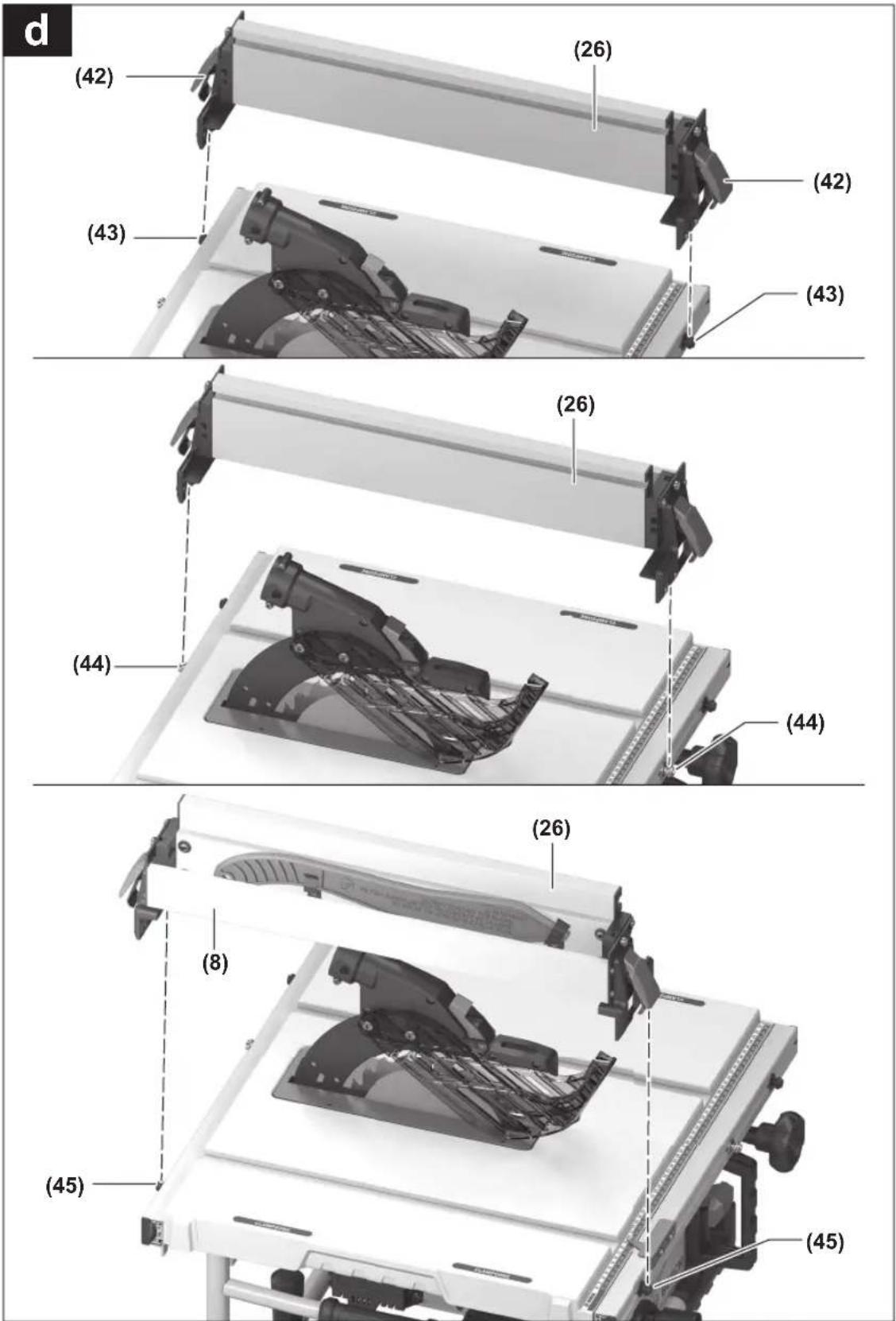
Fitting the Parallel Guide (see figure d)
The parallel guide (26) can be positioned at fixed points on either the left or the right of the saw blade. The three pairs of pins (43), (44), (45) are used for this purpose.
angle guide (1), profile rail (28), length stop (30), protective cover (3), dust extraction adapter (34).
- If you require one of these parts, remove it carefully from its storage location.
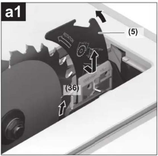
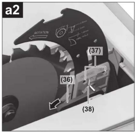
Positioning the Riving Knife (see figures a1-a2)
Note: If necessary, clean all parts to be fitted before you position them.
- Turn the crank (19) clockwise as far as possible so that the saw blade (27) is in the highest possible position above the saw table.
- Release the clamping lever (36) clockwise until it points upwards.
- Slide the riving knife (5) towards the clamping lever (36) until it can be pulled upwards.
– Pull the riving knife all the way up until it is positioned exactly over the centre of the saw blade. - Allow both positioning pins (37) to engage in the lower bore holes in the riving knife and then retighten the clamping lever (36).
The markings (38) on the clamping plate and clamping lever (36) must be aligned as shown.
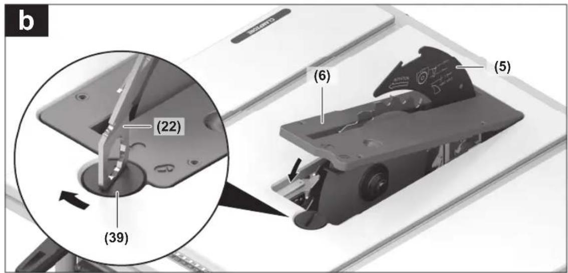
Fitting the Table Insert (see figure b)
- Hook the table insert (6) into the rear recess of the tool chamber and guide it down.
- Press down on the table insert until it engages in the tool chamber.
- Turn the locking screw (39) as far as it will go in the "Lock" direction using the tip of the ring spanner (22).
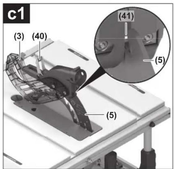
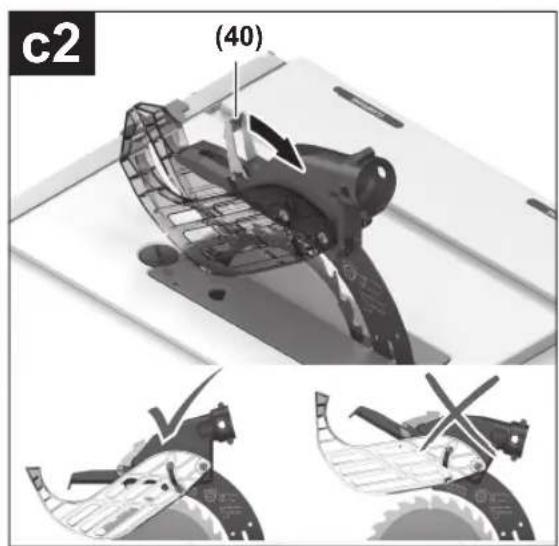
Fitting the protective cover (see figures c1-c2)
Note: Only fit the protective cover when the riving knife is in the top position directly over the centre of the saw blade (see figure a2). Do not fit the protective cover when the riving knife is in the bottom position (position when delivered/position for sawing grooves) (see figure a1).
- Loosen the clamping lever (40) and remove the protective cover (3) from the bracket (10).
- Push the guide pin (41) backwards into the groove on the riving knife (5).
- Move the protective cover (3) down until the saw blade guard (upper plastic rail) is parallel with the surface of the saw table (2).
- Push the clamping lever (40) up. The clamping lever must be felt and heard to engage; the protective cover (3) must be securely and safely fitted.
▶ Always check that the blade guard can move properly before use. Do not use the power tool if the blade guard cannot move freely and does not close immediately.
Pin pair Colour Position of parallel guide (26) Cutting capacity Scale (13)
| (43) | Black Right of saw blade 127–635 mm Bottom, black |
| (44) | Silver Right of saw blade 0–508 mm Top, silver |
| (45) | Black Left of saw blade 0–305 mm Bottom, black |
- Make sure that the clamping handle (24) fixes the saw table expansion in place (clamping handle pressed down).
-
Loosen the locking levers (42) on the parallel guide (26).
-
Position the notches on the parallel guide (26) above one of the three pin pairs (43), (44), (45). The folding additional parallel stop (8) must be facing away from the protective cover (3).
- Fold the locking levers (42) down on both sides to fix the parallel guide in place.
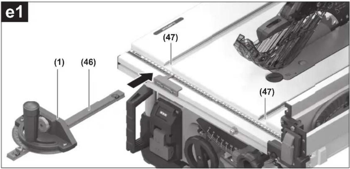
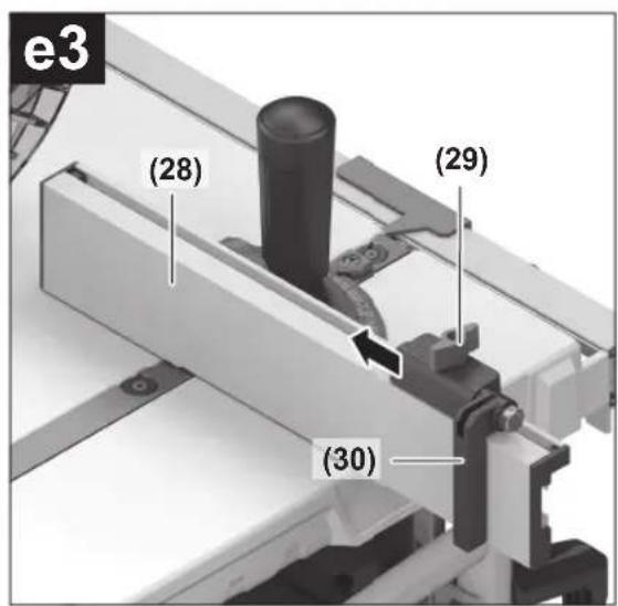
Fitting the Angle Guide, Profile Rail and Length Stop (see figures e1-e3)
- Push the rail (46) of the angle guide (1) into one of the guide grooves (47) provided in the saw table.
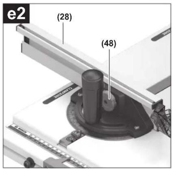
To make it easier to position long workpieces, the angle guide can be extended with the profile rail (28). - If necessary, fit the profile rail (28) on the angle guide using the knurled screw (48).
The length stop (30) can be used for easily sawing workpieces to the same length. - Slide the length stop (30) onto the profile rail (28) and tighten the wing nuts (29) to fix it in place.
Stationary or flexible mounting
▶ To ensure safe handling, the power tool must be mounted on a flat, stable work surface (e.g. work bench) before use.
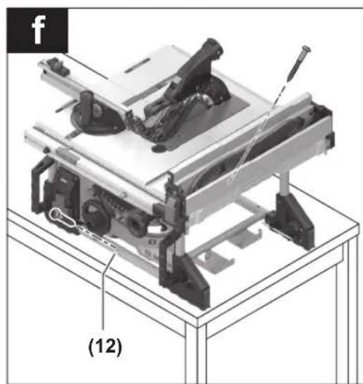
Assembly on a Work Surface (see figure f)
- Use a suitable screwed connection to secure the power tool to the work surface. The holes (12) are used for this purpose.
or - Firmly clamp the base of the power tool to the work surface with commercially available screw clamps.
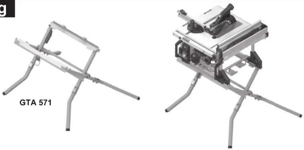
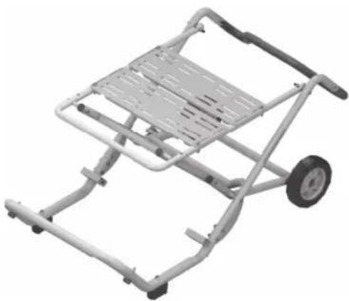
Mounting on a Bosch saw stand (see figure g)
The saw stands by Bosch (e.g. GTA 571) can be easily transported and quickly set up thanks to their foldable design. The power tool can be installed without tools.
Read all the warnings and instructions included with the saw stand. Failure to observe the warnings and follow instructions may result in electric shock, fire and/or serious injury.
▶ Assemble the saw stand properly before mounting the power tool. Correct assembly is important to prevent the risk of collapsing.
- Mount the power tool on the saw stand in the transport position.
Use the positioning handles (11) to align the power tool on the saw stand.
Dust/chip extraction
The dust from materials such as lead paint, some types of wood, minerals and metal can be harmful to human health. Touching or breathing in this dust can trigger allergic reactions and/or cause respiratory illnesses in the user or in people in the near vicinity.
Certain dusts, such as oak or beech dust, are classified as carcinogenic, especially in conjunction with wood treatment additives (chromate, wood preservative). Materials containing asbestos may only be machined by specialists.
- Use a dust extraction system that is suitable for the material wherever possible.
- Provide good ventilation at the workplace.
- It is advisable to wear a P2 filter class breathing mask.
The regulations on the material being machined that apply in the country of use must be observed.
- Avoid dust accumulation at the workplace. Dust can easily ignite.
The dust/chip extraction system can be blocked by dust, chips or fragments of the workpiece.
- Switch the power tool off and remove the battery.
- Wait until the saw blade has come to a complete stop.
– Determine the cause of the blockage and eliminate it.
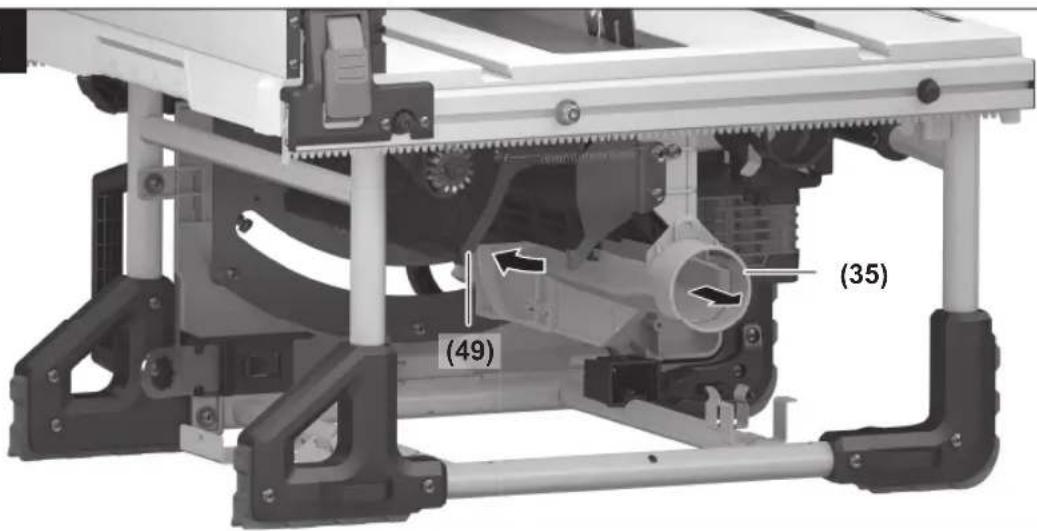
▶ To prevent the risk of fire when sawing aluminium, empty the chip ejector and do not use chip extraction.
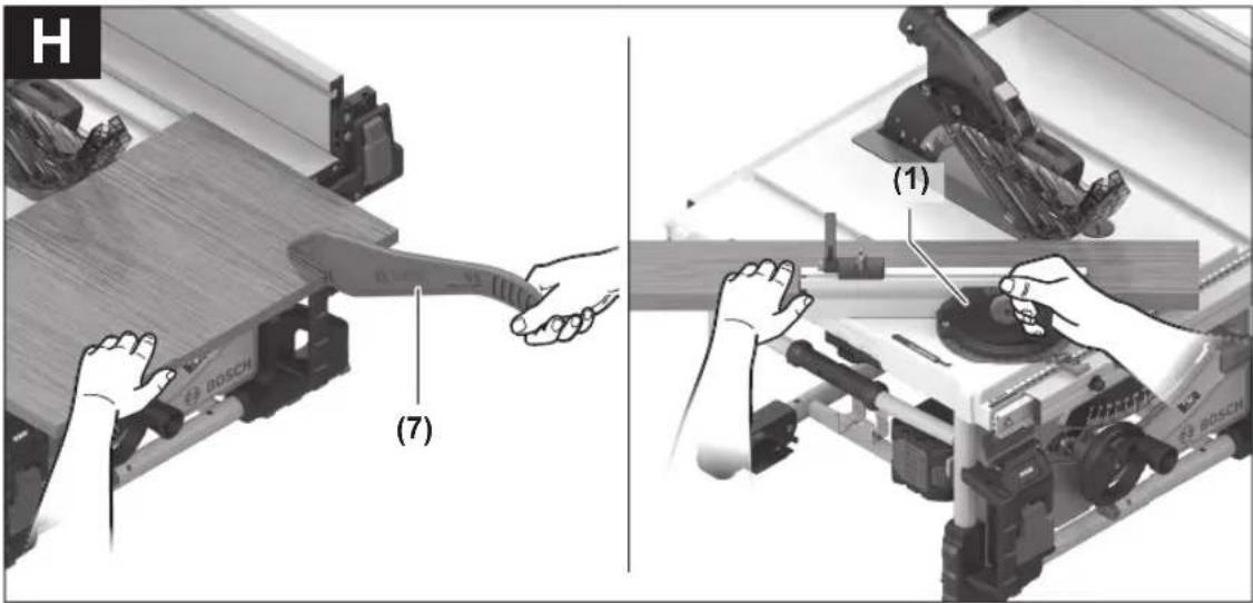
Emptying the Chip Ejector (see figure h)
You can empty the chip ejector (35) to remove workpiece fragments and large chips.
- Switch the power tool off and remove the battery (32).
- Wait until the saw blade has come to a complete stop.
- Swivel the cover cap (49) to the side and pull out the chip ejector (35).
- Shake out the workpiece fragments and chips.
- Swivel the cover cap (49) to the side again and push the chip ejector (35) underneath the saw blade (27) as far as it will go.
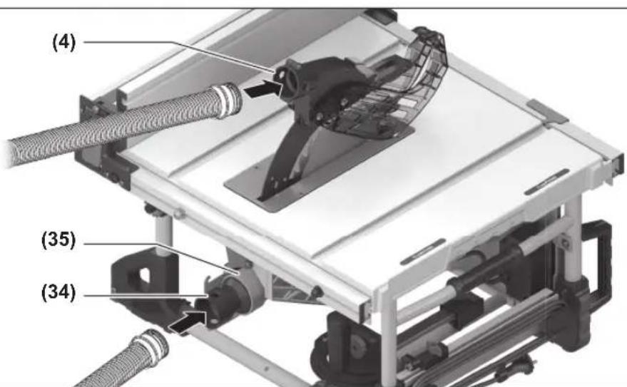
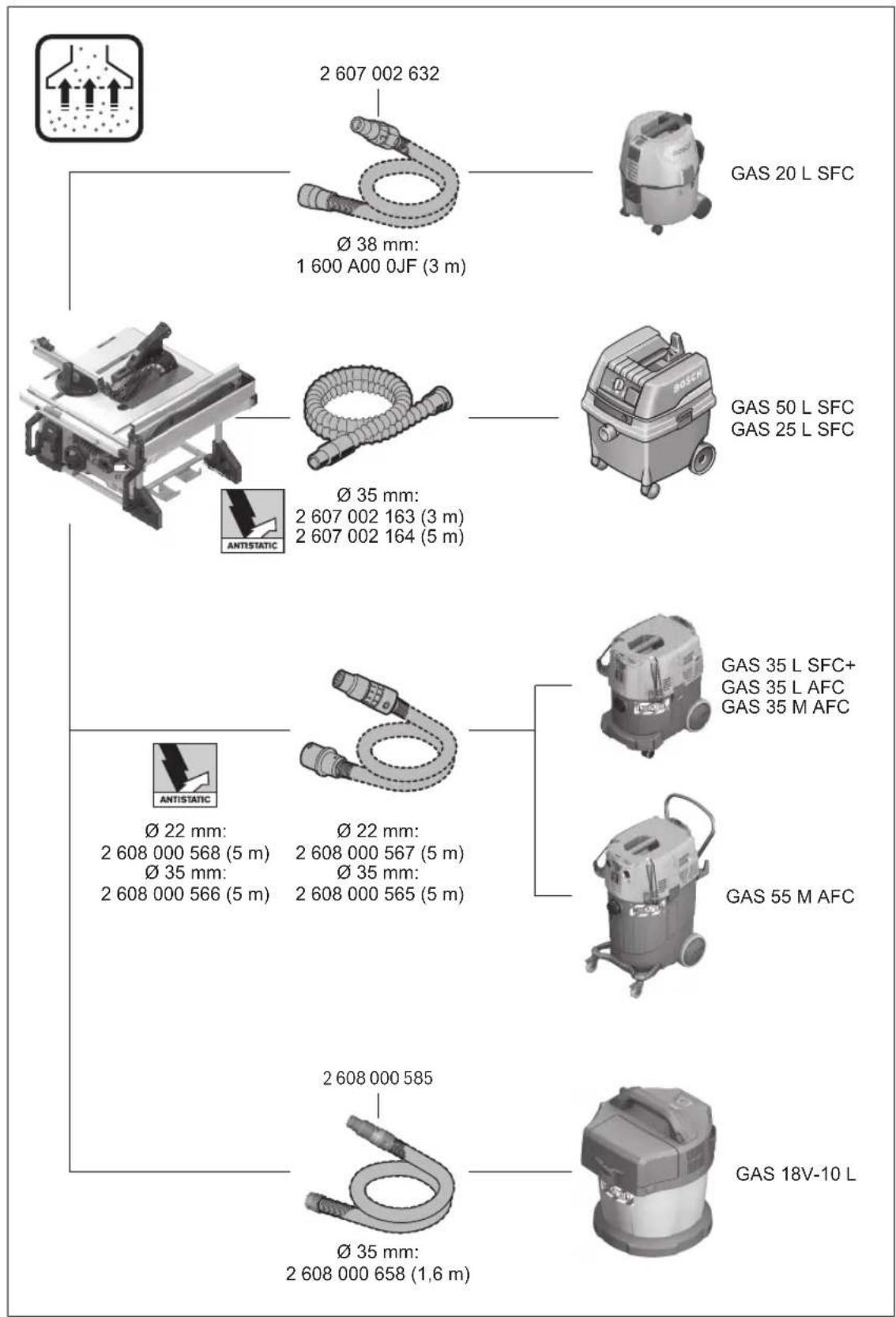
External Dust Extraction (see figure i)
Click & Clean connection: In order to extract dust and chips, you can either connect a dust extraction hose to the dust extraction adapter (4) of the protective cover (3) or connect a dust extraction hose together with the dust extraction adapter (34) to the chip ejector (35).
46 | English
- Connect a dust extraction hose (dia. 33 mm) firmly to the dust extraction adapter (4) of the protective cover (3).
or - Attach the dust extraction adapter (34) firmly to the chip ejector (35).
- Connect a dust extraction hose (dia. 39 mm) firmly to the dust extraction adapter (34).
The dust extractor must be suitable for the material being worked.
When extracting dry dust that is especially detrimental to health or carcinogenic, use a special dust extractor.
Changing the saw blade (see figures j1-j4)
▶ Before carrying out any work on the power tool (e.g. maintenance, tool change etc.), remove the battery from the power tool. There is risk of injury from unintentionally pressing the on/off switch.
▶ When mounting the saw blade, wear protective gloves. This poses a risk of injury.
▶ Only use saw blades the maximum permitted speed of which is higher than the no-load speed of the power tool.
▶ Only use saw blades that match the specifications given in this operating manual and that are tested and marked in accordance with EN 847-1
▶ Only use saw blades that are recommended by the power tool manufacturer and are suitable for use on the material you want to saw. This prevents the saw tooth tips from overheating and the plastic you want to saw from melting.
▶ Do not use HSS saw blades. Such saw blades can easily break.
Removing the saw blade
- Open the clamping lever (40) and pull the protective cover (3) out of the groove on the riving knife (5).
- Turn the locking screw (39) as far as possible in the "Unlock" direction using the tip of the ring spanner (22) and lift the table insert (6) out of the tool chamber. A gripping hole (50) is integrated into the tool for ease of lifting.
- Turn the crank (19) clockwise as far as possible so that the saw blade (27) is in the highest possible position above the saw table.
- Turn the clamping nut (51) using the ring spanner (22) while pulling the spindle locking lever (52) until it engages.
- Keep pulling the spindle locking lever and unscrew the clamping nut anticlockwise.
- Remove the clamping flange (53).
- Remove the saw blade (27).
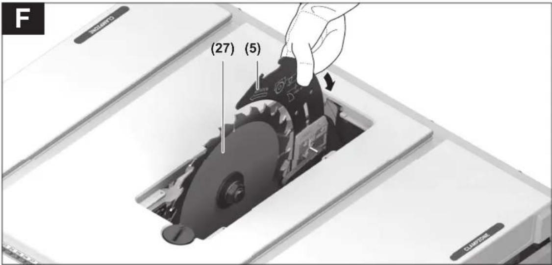
Fitting the saw blade
- If necessary, clean all the parts you want to fit before installing them.
- Place the new saw blade on the mounting flange (54) of the tool spindle (55).
Note: Use sufficiently large saw blades. The radial clearance between the saw blade and the riving knife must not exceed 3–8 mm (max.).
When fitting the saw blade, make sure that the cutting direction of the teeth (direction of the arrow on the saw blade) matches the direction of the arrow on the riving knife.
- Fit the clamping flange (53) and the clamping nut (51).
- Turn the clamping nut (51) using the ring spanner (22) while pulling the spindle locking lever (52) until it engages.
- Tighten the clamping nut by turning it clockwise.
- Place the table insert (6) over the riving knife (5) and into the tool chamber. Turn the locking screw (39) as far as it will go in the "Lock" direction using the tip of the ring spanner (22).
- Refit the protective cover (3).
Operation
▶ Before carrying out any work on the power tool (e.g. maintenance, tool change etc.), remove the battery from the power tool. There is risk of injury from unintentionally pressing the on/off switch.
Transport position and work position of the saw blade
Transport position
- Remove the protective cover (3), remove the table insert (6) and place the riving knife (5) in the bottom position. Reinsert the table insert (6).
- Turn the crank (19) anticlockwise until the teeth of the saw blade (27) lie below the saw table (2).
- Push the saw table expansion (8) in fully. Push the clamping handle (24) down. This fixes the saw table expansion in place.
Work position
- Position the riving knife (5) in the top position directly over the centre of the saw blade, insert the table insert (6) and fit the protective cover (3).
- Turn the crank (19) clockwise until the top teeth of the saw blade (27) are approx. 3–6 mm above the workpiece.
Extending the saw table
The free end of long and heavy workpieces must have something placed underneath it or be supported.
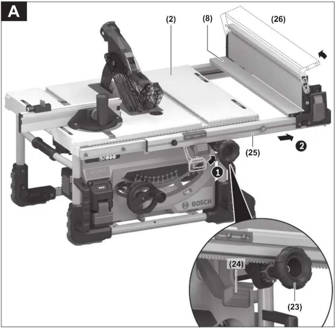
Saw Table Expansion (see figure A)
You can extend the saw table to the left or the right by moving out the guide rail (25).
- Pull the clamping handle (24) for the saw table expansion all the way up.
- Use the rotary knob (23) to move the guide rail (25) out to the left or the right to the required length.
- Push the clamping handle (24) down. This fixes the saw table expansion in place.
Setting mitre and bevel angles
To ensure precise cuts, the basic settings of the power tool must be checked and adjusted as necessary after intensive use.
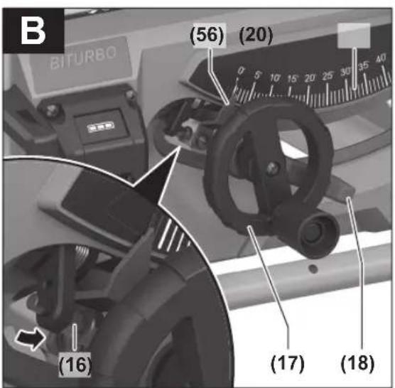
Setting Bevel Angles (Saw Blade) (see figure B)
The bevel angle can be set between -2^ and 47^ .
For quick and precise setting of the standard bevel angles of 0^ and 45^ , there are pre-set stops ((16), (21)).
- Loosen the locking lever (18) by turning it anticlockwise.
Note: When the locking lever is fully loosened, gravity causes the saw blade to tilt into a position that corresponds to approximately 30°.
Bevel angle between 0° and 45°:
- Pull or push the hand wheel (17) along the slotted link until the angle indicator (56) shows the required bevel angle.
- Hold the hand wheel in this position and retighten the locking lever (18).
Bevel angle between -2^ and 0^ :
- Swivel the stop (16) forwards.
- Push the hand wheel (17) along the slotted link until the angle indicator (56) shows the required bevel angle.
- Hold the hand wheel in this position and retighten the locking lever (18).
Bevel angle between 45° and 47°:
- Swivel the stop (21) forwards.
- Pull the hand wheel (17) along the slotted link until the angle indicator (56) shows the required bevel angle.
- Hold the hand wheel in this position and retighten the locking lever (18).
The stops ((16), (21)) automatically swivel back to the standard position as soon as a bevel angle between 0° and 45° is set for the saw blade once again.
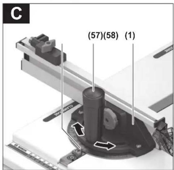
Setting mitre angles (angle guide) (see figure C)
The mitre angle can be set between 30^ (left-hand side) and 30^ (right-hand side).
- Loosen the locking knob (57) if it is tightened.
- Turn the angle guide until the angle indicator (58) shows the required mitre angle.
- Retighten the locking knob (57).
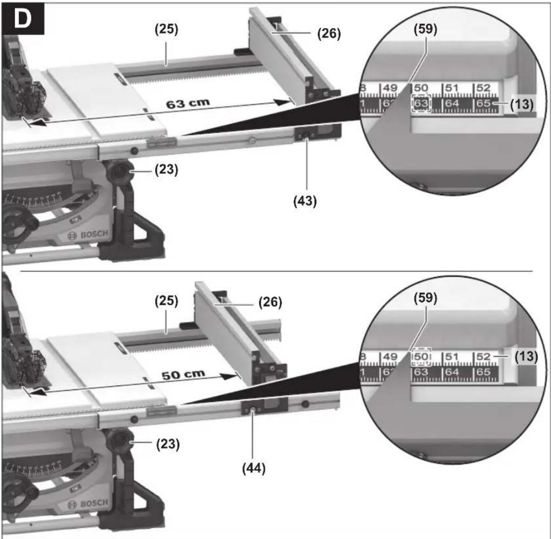
Adjusting the Parallel Guide (see figure D)
The parallel guide (26) can be positioned at fixed points on either the left or the right of the saw blade. The three pairs of pins (43), (44), (45) are used for this purpose.
- Position the parallel guide (26) on the required side of the saw blade (see "Fitting the Parallel Guide (see figure d)", page 44).
- Use the rotary knob (23) to set the required spacing between the parallel guide and the saw blade.
The right-hand edge of the spacing indicator (59) displays the set spacing.
For position (43), (45), the lower black scale (13) applies.
For position (44), the upper, silver scale (13) applies.
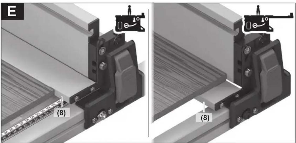
Adjusting the Additional Parallel Guide (see figure E)
- Use the parallel guide (26) to fold the additional parallel guide (8) on the side of the saw blade (27).
Depending on its position, the folding additional parallel guide (8) has two different tasks:
- Stop to saw narrow workpieces and bevel angles if the additional parallel guide is on the saw table (2).
- Workpiece support if the saw table (2) is extended by more than 50.8 mm.
Adjusting the riving knife
The riving knife (5) prevents the saw blade (27) from becoming jammed in the kerf. Otherwise there is a risk of kickback occurring if the saw blade catches in the workpiece. It is therefore important to ensure that the riving knife is set up correctly:
- The radial clearance between the saw blade and the riving knife must not exceed 3–8 mm (max.).
- The thickness of the riving knife must be smaller than the cutting width and larger than the base blade thickness.
- The riving knife must always be aligned with the saw blade.
- For normal cuts, the riving knife must always be in the highest possible position.
Adjusting the Height of the Riving Knife (see figure F)
The height of the riving knife must be adjusted in order to saw grooves.
▶ Only use the power tool for grooving or routing if a suitable protective guard (e.g. tunnel blade guard, featherboard) is in place.
- Open the clamping lever (40) and pull the protective cover (3) out of the groove on the riving knife (5). To prevent damage to the protective guard, store it in the bracket provided (10) on the housing (see figure Q).
- Turn the crank (19) clockwise as far as possible so that the saw blade (27) is in the highest possible position above the saw table.
- Release the clamping lever (36) clockwise until it points upwards.
- Pull the riving knife off the pins (37) (pull the clamping lever (36) outwards slightly) and push the riving knife (5) down as far as possible.
- Allow both pins (37) to engage in the upper bore holes in the riving knife and then retighten the clamping lever (36).
The markings (38) on the clamp and the clamping lever (36) must be aligned (see also figure a2).
48 | English
Start-up
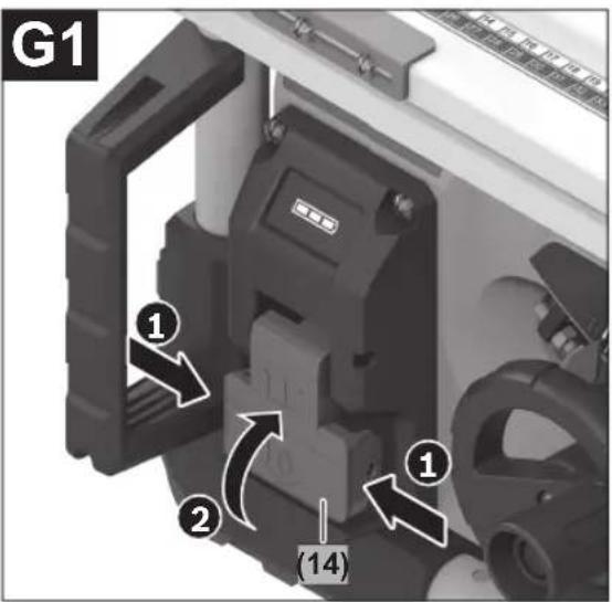
Switching on (see figure G1)
- To start the tool, squeeze both sides of the on/off switch (14) and pull it upwards.
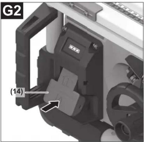
Switching off (see figure G2)
- Press the on/off switch (14) all the way downwards.
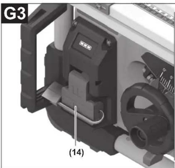
Protection Against Unauthorised Use (see figure G3)
To protect against unauthorised use, you can lock the on/off switch (14) with a padlock.
- Push a padlock with a long shackle through the lower hole in the on/off switch (14) and lock it, or push a normal padlock through the upper hole at the side of the on/off switch housing and lock it.
Practical advice
General sawing instructions
Before making any cuts, first make sure that the saw blade cannot come into contact with the stops or any other parts of the tool at any time.
▶ Only use the power tool for grooving or routing if a suitable protective guard (e.g. tunnel blade guard, featherboard) is in place.
▶ Do not use the power tool for cutting slots (stopped grooves).
Protect the saw blade against impact and shock. Do not subject the saw blade to lateral pressure.
The riving knife must be aligned with the saw blade in order to prevent the workpiece from jamming.
Do not saw workpieces that have become bent or twisted out of shape. The workpiece must always have a straight edge to face against the parallel guide.
Always store the push stick on the power tool.
Position of the operator (see figure H)
▶ Never stand directly in line with the saw blade. Always position your body on the same side of the saw blade as the fence. Kickback may propel the workpiece at high velocity towards anyone standing in front and in line with the saw blade.
- Keep hands, fingers and arms away from the rotating saw blade.
Pay attention to the following instructions:
- Hold the workpiece firmly with both hands and press it securely against the saw table.
- When using narrow workpieces or sawing bevel angles, always use the push stick (7) provided.
Maximum workpiece dimensions
| Bevel angle max. height of the work-piece [mm] | |
| 0° | 70 |
| 45° | 49 |
Sawing
Making straight cuts
- Adjust the parallel guide (26) to the desired cutting width.
- Place the workpiece on the saw table in front of the protective cover (3).
- Use the crank (19) to raise or lower the saw blade as far up or down as needed to position the top teeth of the saw blade (27) approx. 3–6 mm above the workpiece.
- Switch on the power tool.
- Saw through the workpiece applying uniform feed. If you apply too much pressure, the tip of the saw blade could overheat and damage the workpiece.
- Switch off the power tool and wait until the saw blade has come to a complete stop.
Sawing a bevel angle
- Set the required saw blade bevel angle. If the saw blade is tilted to the left, the parallel guide (26) must be to the right of the blade.
- Follow the work steps set out in the (see "Making straight cuts", page 48) section
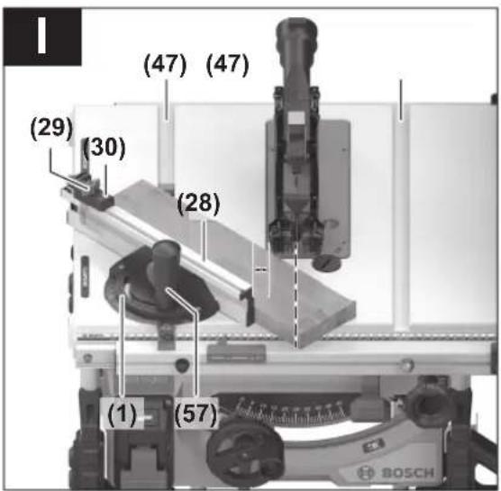
Sawing mitre angles (see figure I)
- Set the required mitre angle on the angle guide (1).
- Place the workpiece on the profile rail (28). The profile rail must not be positioned along the cut line. If it is, loosen the knurled screw (48) and reposition the stop.
- Use the crank (19) to raise or lower the saw blade as far up or down as needed to position the top teeth of the saw blade (27) approx. 3–6 mm above the workpiece.
- Switch on the power tool.
- Hold the workpiece against the profile rail (28) with one hand; place your other hand on the locking knob (57) and slide the angle guide slowly forwards in the guide groove (47).
- Switch off the power tool and wait until the saw blade has come to a complete stop.
The length stop (30) can be used for easily sawing workpieces to the same length.
- Loosen the wing bolt (29) and reposition the length stop (30) to the required workpiece length.
- Retighten the wing bolt (29).
Checking and adjusting the basic settings
To ensure precise cuts, the basic settings of the power tool must be checked and adjusted as necessary after intensive use.
Experience and suitable special tools are required for this.
A Bosch after-sales service point will handle this work quickly and reliably.
Adjusting the stops for a standard bevel angle 0°/45°
- Bring the power tool into the work position.
- Set the saw blade to a bevel angle of 0^ .
- Remove the blade guard (3).
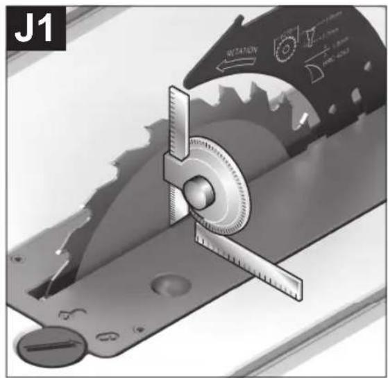
Checking (see figure J1)
- Set an angle gauge to 90^ and place it on the saw table (2).
The leg of the angle gauge must be flush with the saw blade (27) along its entire length.
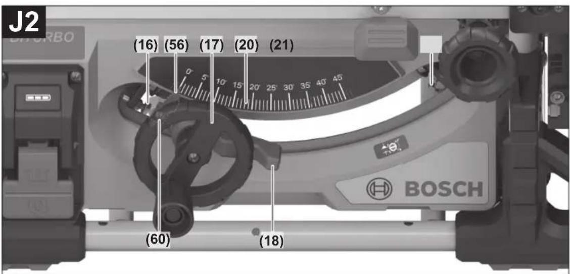
Setting (see figure J2)
- Loosen the lock nut of the stop screw (16) using a commercially available box-ended or open-ended spanner.
- Loosen the locking lever (18).
- Push the handwheel (17) against the stop screw (16) and turn the stop screw as far in or out as needed until the leg of the angle gauge is flush with the saw blade along its entire length.
- Hold the hand wheel in this position and retighten the locking lever (18).
- Retighten the lock nut of the stop screw (16).
If the angle indicator (56) is not aligned with the 0^ mark on the scale (20) following adjustment, loosen the screw (60) using a commercially available cross-headed screwdriver and align the angle indicator along the 0^ mark.
Repeat the above work steps for the bevel angle of 45^ (loosen the lock nut; adjust the stop screw (21)). The angle indicator (56) must not be repositioned when doing this.
Parallelism of the saw blade with the guide grooves of the angle guide (see figure K)
- Bring the power tool into the work position.
- Remove the blade guard (3).
Checking
- Use a pencil to mark the first left-hand saw tooth that is visible at the back above the table insert.
- Set an angle gauge to 90^ and place it on the edge of the guide groove (47).
- Move the leg of the angle gauge until it touches the marked saw tooth and read the distance between the saw blade and the guide groove.
- Turn the saw blade until the marked tooth at the front lies above the table insert.
- Move the angle gauge along the guide groove up to the marked saw tooth.
- Measure the distance between the saw blade and the guide groove again.
The two measured distances must be identical.
Setting
- Loosen the hex socket screws (61) at the front beneath the saw table and the hex socket screws (62) at the rear beneath the saw table using the hex key (9) provided.
- Carefully move the saw blade until it lies parallel with the guide groove (47).
- Retighten all screws (61) and (62).
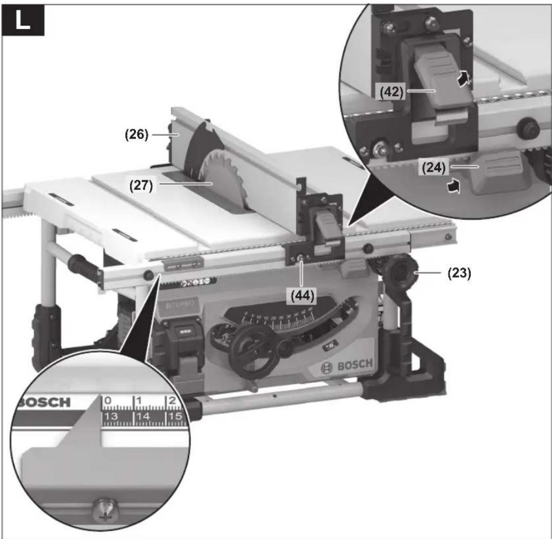
Aligning the Parallel Guide - Pin Pair (44), Silver, Right (see figure L)
Before aligning the parallel guide (26), you must first adjust the stops (16)/(21) for the standard bevel angles and ensure that the saw blade (27) is parallel with the guide grooves (47) of the angle guide.
(see "Adjusting the stops for a standard bevel angle 0^ / 45^ ", page 48)
(see "Parallelism of the saw blade with the guide grooves of the angle guide (see figure K)", page 49)
- Loosen the locking levers (42) on the parallel guide (26) and allow the parallel guide to move freely during the entire aligning process.
- Position the notches on the parallel guide (26) above pin pair (44) (silver). The folding additional parallel stop (8) must be facing away from the protective cover (3).
- Remove the protective cover (3).
- Pull the clamping handle (24) for the saw table expansion all the way up and reposition the parallel guide (26) until it is touching the saw blade (27).
Checking
The parallel guide (26) must touch the saw blade along its entire length.
Adjusting
- Loosen the silver screws of the pin pair (44) with the supplied hex key (9) enough so that the pins can glide freely.
- Use the parallel guide (44) to push the pin pair (26) approx. 3 mm to the right.
- Use the rotary knob (23) on the upper, silver scale (13) to set a spacing of 0mm between the parallel guide and the saw blade.
- Push the clamping handle (24) for the saw table expansion down.
- Use the parallel guide (26) to push the pin pair (44) to the left until the parallel guide is touching the saw blade along its entire length.
- Carefully tighten the silver screws of the pin pair (44) using the supplied hex key (9).
- Fold the locking levers (42) down on both sides to fix the parallel guide in place.
- Make sure that the parallel guide is still touching the saw blade along its entire length after tightening.
Then check black pin pairs (43) and (45).
Aligning the Parallel Guide - Pin Pair (43), Black, Right (see figure M)
Before aligning pin pair (43), you first need to align pin pair (44) (silver, right) correctly.
(see "Aligning the Parallel Guide – Pin Pair (44), Silver, Right (see figure L)", page 49)
- Loosen the locking levers (42) on the parallel guide (26) and lift the parallel guide off the pin pair (44).
- Loosen the black screws of pin pair (43) with the supplied hex key (9) such that the pins can glide freely.
- Hold the recesses of the ring spanner (22) against the front pins (44)/(43).
- Move the black pin (43) until the two pins (silver (44) and black (43)) fit in the relevant recess of the ring spanner.
- Repeat these actions with the rear pins (44)/(43).
50 | English
Aligning the Parallel Guide - Pin Pair (45), Black, Left
Before aligning the parallel guide (26), you must first adjust the stops (16)/(21) for the standard bevel angles and ensure that the saw blade (27) is parallel with the guide grooves (47) of the angle guide.
(see "Adjusting the stops for a standard bevel angle 0^ / 45^ ", page 48)
(see "Parallelism of the saw blade with the guide grooves of the angle guide (see figure K)", page 49)
- Loosen the locking levers (42) on the parallel guide (26) and allow the parallel guide to move freely during the entire aligning process.
- Position the notches on the parallel guide (26) above pin pair (45) (black). The folding additional parallel stop (8) must be facing away from the protective cover (3).
- Remove the protective cover (3).
- Pull the clamping handle (24) for the saw table expansion all the way up and reposition the parallel guide (26) until it is touching the saw blade (27).
Checking
The parallel guide (26) must touch the saw blade along its entire length.
Adjusting
- Loosen the black screws of pin pair (45) with the supplied hex key (9) such that the pins can glide freely.
- Use the parallel guide (26) to push pin pair (45) to the right until the parallel guide is touching the saw blade along its entire length.
- Carefully tighten the black screws of the pin pair (45) using the supplied hex key (9).
- Fold the locking levers (42) down on both sides to fix the parallel guide in place.
- Make sure that the parallel guide is still touching the saw blade along its entire length after tightening.
Adjusting the saw table spacing indicator (see figure N)
- Loosen the locking levers (42) on the parallel guide (26) and allow the parallel guide to move freely during the entire aligning process.
- Position the notches on the parallel guide (26) above pin pair (44) (silver). The folding additional parallel stop (8) must be facing away from the protective cover (3).
- Remove the protective cover (3).
- Pull the clamping handle (24) for the saw table expansion all the way up and reposition the parallel guide (26) until it is touching the saw blade (27).
- Loosen the screws (63) with a cross-headed screwdriver and align the spacing indicator (59) along the 0 mark on the scale (13).
- Retighten the screws (63).
Adjusting the level of the table insert (see figure 0) Checking
The front side of the table insert (6) must lie flush with or a little below the saw table; the rear must lie flush with or a little above the saw table.
Setting
- Use the hex key (9) to set the correct level of the four adjusting screws (64).
Adjusting the Play of the Guide Rail Angle Guide in the Guide Groove (see figure P)
After intensive use, the play of the guide rail (46) of the angle guide in the guide groove (47) may be too large.
- Retighten the adjustment screws (65) of the guide rail (46).
Storage and transport
Storing Tool Elements (see figure Q)
You can attach certain tool elements to the power tool to store them.
- Place all loose tool elements in their brackets on the housing (see the table below).
Tool element Storage
| Protective cover (3) Bracket (10); tighten with clamping lever (40) | |
| Angle guide (1) Holder (33) | |
| Dust extraction adapter (34) | see figure Q |
| Ring spanner (22) see figure Q | |
| Hex key (9) see figure Q | |
| Push stick (7) | Hook into the bracket between the parallel guide (26) and the additional parallel guide (8) |
| Parallel guide (26) | Turn around, position from below into the guide rail (25) using the pin pair (43) and secure the locking levers (42) |
Transporting the Power Tool (see figure R)
Before transporting the power tool, the following steps must be carried out:
- Bring the power tool into the transport position (see "Transport position", page 46).
- Remove all accessories that cannot be securely fitted to the power tool. If possible, transport unused saw blades in an enclosed container.
- Slide the guide rail (25) all the way in and press the clamping handle (24) down to fix it in place.
- Use the carrying handle (66) or the recessed handles (67) to lift or transport the tool. Do not use the positioning handles (11) for this purpose.
▶ Only use the transport devices to transport the power tool and never the protective devices.
Maintenance and Service
Maintenance and Cleaning
Before carrying out any work on the power tool (e.g. maintenance, tool change etc.), remove the battery from the power tool. There is risk of injury from unintentionally pressing the on/off switch.
▶ To ensure safe and efficient operation, always keep the power tool and the ventilation slots clean.
Cleaning
Always remove dust and chips after working by blowing out with compressed air or using a brush.
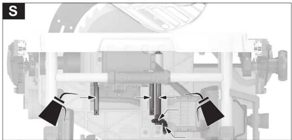
Lubricating the power tool

Oil the power tool as necessary at the points indicated (see figure S).
An authorised Bosch after-sales service centre will handle this work quickly and reliably.
▶ Dispose of lubricants and cleaning products in an environmentally friendly manner, taking legal regulations into account.
Noise reduction measures
Measures implemented by the manufacturer:
- Soft start
– Provided with a saw blade specially developed for noise reduction
Measures implemented by the operator:
– Low-vibration mounting on a stable work surface
- Use of saw blades with noise-reducing functions
- Regular cleaning of the saw blade and power tool
After-Sales Service and Application Service
Great Britain
Tel. Service: (0344) 7360109
Malaysia
Tel.: (03) 79663194

You can find our service addresses and links to the repair service and spare parts ordering at www.bosch-pt.com/serviceaddresses
In all correspondence and spare parts orders, please always include the 10-digit article number given on the nameplate of the product.
Disposal
Power tools, rechargeable batteries, accessories and packaging should be sorted for environmental-friendly recycling.
Do not dispose of power tools and batteries/re-chargeable batteries into household waste!
Only for EU countries and United Kingdom:
Electrical and electronic equipment or used batteries that are no longer suitable for use must be collected separately and disposed of in an environmentally friendly manner. Use the designated collection systems. Incorrect disposal may cause harmful effects on the environment and human health, due to the potential presence of hazardous substances.
Français
www.bosch-pt.com/serviceaddresses
Calle Robert Bosch No. 405
www.bosch-pt.com/serviceaddresses
- Afzuigadapter (34)
Stationaire of flexibele montage
Tlf. Service Center: 44898855

Du kan finde vores serviceadresser og links til reparationsservice og bestilling af reservedele på: www.bosch-pt.com/serviceaddresses
(12) Boringer for montering
www.bosch-pt.com/serviceaddresses
www.bosch-pt.com/serviceaddresses
| Dritë e vazhdueshme 3 × jeshile 60–100 % |
| Dritë e vazhdueshme 2 × jeshile 30–60 % |
| Dritë e vazhdueshme 1 × jeshile 5–30 % |
Dritë pulsuese 1 × jeshile 0–5 %
Mbrojtje nga mbingarkesa e varur nga temperatura
www.bosch-pt.com/serviceaddresses
Molimo da kod svih pitanja i naručivanja rezervnih delova neizostavno navedete broj artikla sa 10 brojčanih mesta prema tipskoj pločici proizvoda.
Uklanjanje dubreta
Električne alate, akumulacione baterije, pribor i pakovanja treba predati na reciklažu koja je u skladu sa zaštitom životne sredine.
Ne bacajte električne alate i akumulatore/baterije u kućno djubre!
Samo za EU-zemlje:
Električni i elektronski uređaji ili istrošeni akumulatori i baterije koji više ne mogu da se koriste moraju da se skupljaju zasebno i odlože u otpad u skladu sa ekološkim propisima. Koristite naznačene sisteme za sakupljanje. Zbog mogućih opasnih materija koji se nalaze u uređaju, nepravilno odlaganje u otpad može da bude opasno za okolinu i zdravlje.
Slovenščina
Varnostna opozorila
Shranjevanje in transport
must saelehest paremal 127–635 mm all, must
www.bosch-pt.com/serviceaddresses
www.bosch-pt.com/serviceaddresses
ل Effect. Departices Marketing for the Practure of the Practure of the Practure of the Practure of the Practure of the Practure of the Practure of the Practure of the Practure of the Practure of the Practure of the Practure of the Practure of the Practure of the Practure of the Practure of the Practure of the Practure of the Practure of the Practure of the Practure.
natural_image
Simple line drawing of a paperclip inside a circle with two abstract shapes above (no text or symbols)Affordable Manufacturers.
natural_image
Metal folding table frame with adjustable legs and support brackets (no text or symbols visible)GTA 571
0 601 B22 800
natural_image
3D rendering of a metal folding chair with wheels and structural brackets (no text or symbols)GTA 50 W
0 601 B57 000
Legal Information and Licenses
1- Open Source Components
1.1 ARM (BSD 3-clause)
CMSIS-core 4 Copyright © 2009-2020 ARM LIMITED
All rights reserved.
- Redistribution and use in source and binary forms, with or without modification, are permitted provided that the following conditions are met.
- Redistributions of source code must retain the above copyright notice, this list of conditions and the following disclaimer.
– Redistributions in binary form must reproduce the above copyright notice, this list of conditions and the following disclaimer in the documentation and/or other materials provided with the distribution. - Neither the name of ARM nor the names of its contributors may be used to endorse or promote products derived from this software without specific prior written permission.
THIS SOFTWARE IS PROVIDED BY THE COPYRIGHT HOLDERS AND CONTRIBUTORS "AS IS" AND ANY EXPRESS OR IMPLIED WARRANTIES, INCLUDING, BUT NOT LIMITED TO, THE IMPLIED WARRANTIES OF MERCHANTABILITY AND FITNESS FOR A PARTICULAR PURPOSE ARE DISCLAIMED. IN NO EVENT SHALL THE COPYRIGHT OWNER OR CONTRIBUTORS BE LIABLE FOR ANY DIRECT, INDIRECT, INCIDENTAL, SPECIAL, EXEMPLARY, OR CONSEQUENTIAL DAMAGES (INCLUDING, BUT NOT LIMITED TO, PROCUREMENT OF SUBSTITUTE GOODS OR SERVICES; LOSS OF USE, DATA, OR PROFITS; OR BUSINESS INTERRUPTION) HOWEVER CAUSED AND ON ANY THEORY OF LIABILITY, WHETHER IN CONTRACT, STRICT LIABILITY, OR TORT (INCLUDING NEGLIGENCE OR OTHERWISE) ARISING IN ANY WAY OUT OF THE USE OF THIS SOFTWARE, EVEN IF ADVISED OF THE POSSIBILITY OF SUCH DAMAGE.
1.2 Aimonen (zlib) - Nanopb Copyright © 2011 Petteri Aimonen
This software is provided "as-is", without any express or implied warranty. In no event will the authors be held liable for any damages arising from the use of this software. Permission is granted to anyone to use this software for any purpose, including commercial applications, and to alter it and redistribute it freely, subject to the following restrictions:
- The origin of this software must not be misrepresented; you must not claim that you wrote the original software. If you use this software in a product, an acknowledgement in the product documentation would be appreciated but is not required.
- Altered source versions must be plainly marked as such, and must not be misrepresented as being the original software.
- This notice may not be removed or altered from any source distribution.
2- Warranty Disclaimer
This product contains Open Source Software components which underly Open Source Software Licenses. Please note that Open Source Licenses contain disclaimer clauses. The text of the Open Source Licenses that apply are included in this manual under "Legal Information and Licenses".
Legal Information and Licenses
CE
|
| de | EU-Konformitätserklärung | Wir erklären in alleiniger Verantwortung, dass die genannten Produkte allen einschlägigen Bestimmungen der nachfolgend aufgeführten Richtlinien und Verordnungen entsprechen und mit folgenden Normen übereinstimmen. | |
| Akku-Tischkreissäge | Sachnummer | ||
| en | EU Declaration of Conformity | We declare under our sole responsibility that the stated products comply with all applicable provisions of the directives and regulations listed below and are in conformity with the following standards. | |
| Cordless table saw | Article number | ||
| fr | Déclaration de conformité UE | Nous déclarons sous notre propre responsabilité que les produits décrits sont en conformité avec les directives, règlements normatifs et normes énumérés ci-dessous. | |
| Scie sur table sans-fil | N° d'article | ||
| es | Declaración de conformidad UE | Declaramos bajo nuestra exclusiva responsabilidad, que los productos nombrados cumplen con todas las disposiciones correspondientes de las Directivas y los Reglamentos mencionados a continuación y están en conformidad con las siguientes normas. | |
| Sierra circular de mesa a batería | N° de artículo | ||
| pt | Declaração de Conformidade UE | Declaramos sob nossa exclusiva responsabilidade que os produtos mencionados cumprem todas as disposições e os regulamentos indicados e estão em conformidade com as seguintes normas. | |
| Serra de mesa sem fio | N.° do produto | ||
| it | Dichiarazione di conformità UE | Dichiariamo sotto la nostra piena responsabilità che i prodotti indicati sono conformi a tutte le disposizioni pertinenti delle Direttive e dei Regolamenti elencati di seguito, nonché alle seguenti Normative. | |
| Banco sega a batteria | Codice prodotto | ||
| nl | EU-conformiteitsverklaring | Wij verklaren op eigen verantwoordelijkheid dat de genoemde producten voldoen aan alle desbetreffende bepalingen van de hierna genoemde richtlijnen en verordeningen en overeenstemmen met de volgende normen. | |
| Accutafelcirkelza ag-machine | Productnummer | ||
| da | EU-overensstemmelseserklæring | Vi erklærer som eneansvarlige, at det beskrevne produkt er i overensstemmelse med alle gældende bestemmelser i fölgende direktiver og forordninger og opfylder fölgende standarder. | |
| Akku-bordrundsav | Typenummer | ||
| sv | EU-konformitetsförklaring | Vi förklarar under eget ansvar att de nämnda produkterna uppfyller kraven i alla gällande bestämmelser i de nedan angivna direktiven och förordningarnas och att de stämmer överens med följande normer. | |
| Sladdlös bordscirkelsåg | Produktnummer | ||
| no | EU-samsvarserklæring | Vi erklærer under eneansvar at de nevnte produktene er i overensstemmelse med alle relevante bestemmelser i direktivene og forordningene nedenfor og med fölgende standarder. | |
| Batteridrevet bordsirkelsag | Produktnummer | ||
| fi | EU-vaatimustenmukaisuusvakuutus | Vakuutamme täten, että mainitut tuotteet vastaavat kaikkia seuraavien direktiivien ja asetusten asiaankuuluvia vaatimuksia ja ovat seuraavien standardien vaatimusten mukaisia. | |
| Akkupöytäsaha | Tuotenumero | ||
| el | Δήλωση πιστότητας EE | Δηλώνουμε με αποκλειστική μας ευθύνη, ότι τα αναφερόμενα προϊόντα αντιστοιχούν σε όλες τις σχετικές διατάξεις των πιο κάτω αναφερόμενων οδηγιών και κανονισμών και ταυτίζονται με τα ακόλουθα πρότυπα. | |
| Σταθερό δισκοπριονο μπαταρίας | Αριθμός ευρετηρίου | ||
| tr | AB Uygunluk beyani | Tek sorumlu olarak, tanimlanan ürünün aşağıdaki yönetmelik ve direktiflerin geçerli bütün hükümlerine ve aşağıdaki standartlara uygun olduğunu beyan ederiz. | |
| Akülü tezgah tipi daire testere | Ürün kodu | ||
| pl | Deklaracja zgodności UE | Oświadczamy z pełną odpowiedzialnością, że niniejsze produkty odpowiadają wszystkim wymaganiom poniżej wyszczególnionych dyrektyw i rozporządzeń, oraz że są zgodne z następującymi normami. | |
| Akumulatorowa pilarka stołowa | Numer katalogowy | ||
| cs | EU prohlášení o shodě | Prohlašujeme na výhradní zodpovědnost, že uvedený výrobek splňuje všechna příslušná ustanovení niže uvedených směrnic anařizení aje vsouladu snásledujícími normami: | |
| Akumulátorová stolní okružní pila | Objednací číslo | ||
||
CE
| sk | EÚ vyhlásenie o zhode | Vyhlasujeme na výhradnú zodpovednosť, že uvedený výrobok spíňa všetky príslušné ustanovenia nižšie uvedených smerníc anariadení aje vsúlade snasledujúcimi normami: | |
| Akumulátorová stolová okružná píla | Vecné číslo | ||
| hu | EU konformitási nyilatkozat | Egyedüli felelőséggel kijelentjük, hogy a megnevezett termékek megfelelnek az alábbiakban felsorolásra kerülő irányelvek és rendeletek valamennyi idevágó előírásainak és megfelelnek a következő szabványoknak. | |
| Akkus asztali körfűrész | Cikkszám | ||
| ru | Заявление о соответствии EC | Мы заявляем под нашу единоличную ответственность, что названные продукты соответствуют всем действующим предписаниям нижеуказанных директив и распоряжений, а также нижеуказанных норм. | |
| Аккумуляторная настольная дисковая пила | Товарный No | ||
| uk | Заява про відповідність ЄС | Мизаявляємо під нашу одноособову відповідальність, що названі вироби відповідають усім чинним положенням нищеозначених директив і розпоряджень, а також нижчеозначеним нормам. | |
| Акумуляторна настільна дискова пила | Товарний номер | ||
| kk | EO сәйкестік мағлумдамасы | Өз жауапкершілікпен біз аталған өнімдер төменде жзылған директикалар мен жарлықтардың тиісті қағидаларына сәйкестігін және теменdegі нормаларға сай екенін білдіреміз. | |
| Аккумулятормен жұмыс істейтін дискілі үстел арасы | Өнім нөмірі | ||
| ro | Declaratie de conformitate UE | Declarăm pe proprie răspundere că produsele mentionate corespund tuturor dispozițiilor relevante ale directivelor și reglementărilor enumerate în cele ce urmează și sunt în conformitate cu următoarele standarde. | |
| Ferăstrău circular | Număr de identificare | ||
| bg | EC декларация за съответствие | С пълна отговорност ние декларираме, че посочените продукти отговарят на всички валидни изисквания на директивите и разпоредбите по-долу и съответства на следните стандарти. | |
| Акумулаторен настолен циркуляр | Каталожен номер | ||
| mk | EU-Изјава за сообразност | Со целосна одговорност изјавуваме, дека опишаните производи се во согласност со сите релевантни одредби на следните регулативи и прописи и се во согласност со следните норми. | |
| Батериска столна тркалезна пила | Број на дел/артик | ||
| sq | Deklarata EU e konformitetit | Ne deklarojmë nën përgjegjësinë tonë të vetme se produktet e deklaruara përmbushin të gjitha dispozitat e zbatueshme të direktivave dhe rregulloreve të renditura më poshtë dhe janë në përputhje me standardet e mëposhtme. | |
| Sharrë tavoline me bateri | Kodi i artikullit | ||
| sr | EU-izjava o usaglašenosti | Na sopstvenu odgovornost izjavljujemo, da navedeni proizvodi odgovaraju svim dotičnim odredbama naknadno navedenih smernica u uredaba i da su u skladu sa sledećim standardima. | |
| Akumulatorska stona kružna testera | Broj predmeta | ||
| sl | Izjava o skladnosti EU | Izjavljamo pod izključno odgovornostjo, da je omenjen izdelek v skladu z vsemi relevantnimi določili direktiv in uredb ter ustreza naslednjim standardom. | |
| Akumulatorska namizna krožna žaga | Številka artikla | ||
| hr | EU izjava o sukladnosti | Pod punom odgovornošću izjavljujemo da navedeni proizvodi odgovaraju svim relevantnim odredbama direktiva i propisima navedenima u nastavku i da su sukladni sa sljedećim normama. | |
| Akumulatorska stolna kružna pila | Kataloški br. | ||
| et | EL-vastavusdeklaratsioon | Kinnitame ainuvastutajatena, et nimetatud tooted vastavad järgnevalt loetletud direktiivide ja määruste kõikidele asjaomastele nõuetele ja on kooskõlas järgmiste normidega. | |
| Akuga lauaketassaag | Tootenumber | ||
CE
III
Head of Product Certification
i.v. h=mc
Robert Bosch Power Tools GmbH, 70538 Stuttgart, GERMANY
Stuttgart, 24.02.2025
VI
CE
Declaration of Conformity
Cordless table saw
Article number
GTS 18V-70
3 601 M44 100
We declare under our sole responsibility that the stated products comply with all applicable provisions of the regulations listed below and are in conformity with the following standards.
Technical file at: Robert Bosch Ltd. (PT/SOP-GB), Broadwater Park, North Orbital Road, Uxbridge UB9 5HJ, United Kingdom
2006/42/EC - Machinery Directive (EU)
The Electromagnetic Compatibility Regulations 2016
The Restriction of the Use of Certain Hazardous Substances in Electrical and Electronic Equipment Regulations 2012
EN 62841-1:2015+A11:2022
EN 62841-3-1:2014+A11:2017+A1:2021+A12:2021
EN IEC 55014-1:2021
EN IEC 55014-2:2021
EN IEC 63000:2018
EC Type examination no. 4811001.25002 by notified body no. 0158.
DEKRA Testing and Certification GmbH, Handwerkstraße 15, 70565 Stuttgart, GERMANY

BOSCH
Robert Bosch Power Tools GmbH, 70538 Stuttgart, Germany represented (in terms of the above regulations) by
Robert Bosch Limited, Broadwater Park, North Orbital Road, Uxbridge UB9 5HJ, United Kingdom
Steve Neumann
Regional Business Director UK & Ireland

Martin Sibley
Business Operations and Aftersales Director

Robert Bosch Ltd. Broadwater Park, North Orbital Road, Uxbridge UB9 5HJ, United Kingdom, as authorised representative acting on behalf of Robert Bosch Power Tools GmbH, 70538 Stuttgart, Germany
Place of issue: Uxbridge Date of issue: 24/02/2025