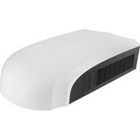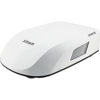
RTA-2600i - Air Conditioning Mestic - Free user manual and instructions
Find the device manual for free RTA-2600i Mestic in PDF.


User questions about RTA-2600i Mestic
0 question about this device. Answer the ones you know or ask your own.
Ask a new question about this device
Download the instructions for your Air Conditioning in PDF format for free! Find your manual RTA-2600i - Mestic and take your electronic device back in hand. On this page are published all the documents necessary for the use of your device. RTA-2600i by Mestic.
USER MANUAL RTA-2600i Mestic
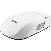
ROOFTOP AIR CONDITIONER RTA-2600I
Voltage: 220-240 AC
Frequency: 50 Hz
Cooling mode
Power: 2650 W
Power input: 950 W
Heating mode
Power: 2500 W
Power input: 780 W
Net weight 29.5 KG
Rated input: 1300 W
Refrigerant: R32
Refr. Charge: 0.37 KG
GWP: 675
CO2 equivalent: 0.25 Tonnes
Waterproof grade: IPX4
Production batch: YYYYY.MM
S/N: INK-
Contains fluorinated greenhouse gas
Imported by:
ROOFTOP AIR CONDITIONER RTA-2600I
Voltage: 220-240 AC
Frequency: 50 Hz
Cooling mode
Power: 2650W
Power input: 950 W
Heating mode
Power: 2500W
Power input: 780 W
Net weight: 2.7 KG
S/N: INK-
Production batch: YYYYY.MM
Imported by:
GIDS VOOR PROBLEEMOPISSING 23
FOUTCODE 24
NORMALE ONDERHOUDSPROCEDURES 24
HANDLEIDING VOOR SPECIALISTEN 24
Roof Top Air Conditioner
INPAKLIJST
| owner's manual | Mounting plate | remote controller | battery (AAA 1.5V) |
| Double-sided gummed paper | Remote controller holder | Sunk screw (remote controller holder) | foam(under) |
| Foam (accessory) | Sponge (foam accessory) | Mounting plate sub-assy | Bolt sub-assy M8X135 |
| Sponge (sealing strip) | Sponge | Insulating sheath | Bundle |
| Bolt sub-assy M6X25 | Tapping screw |
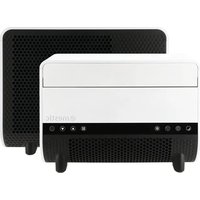
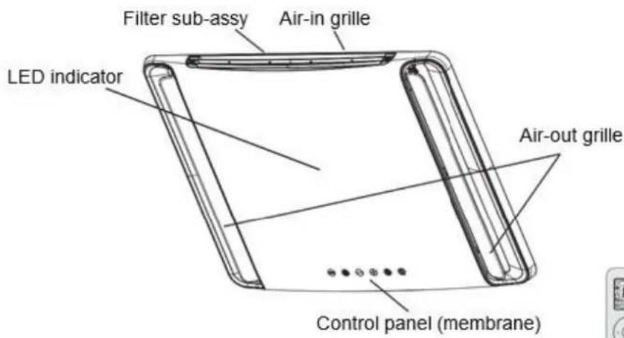
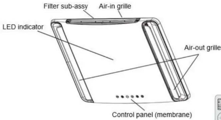
Indoor Unit
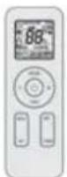
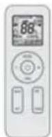
remote controller
(Display content or position may be different from above graphics, please refer to actual products)
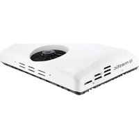
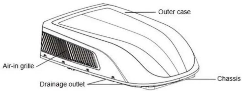
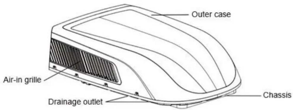
Outdoor Unit
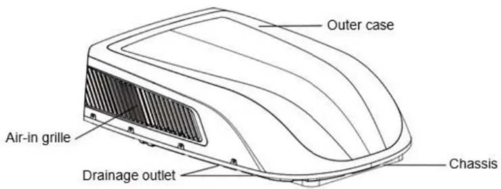
NOTICE:
Actual product may be different from above graphics, please refer to actual products.
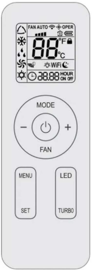
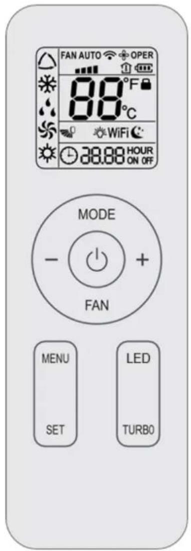
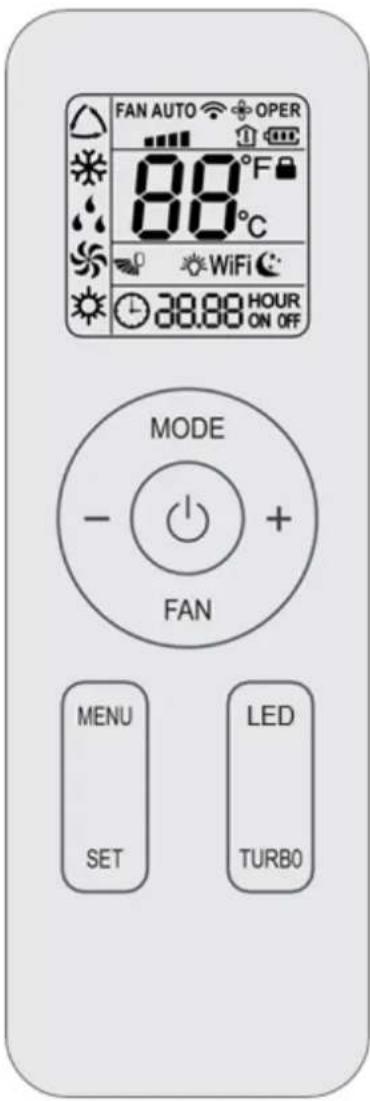
Buttons on remote controller
Introduction for icons on display screen
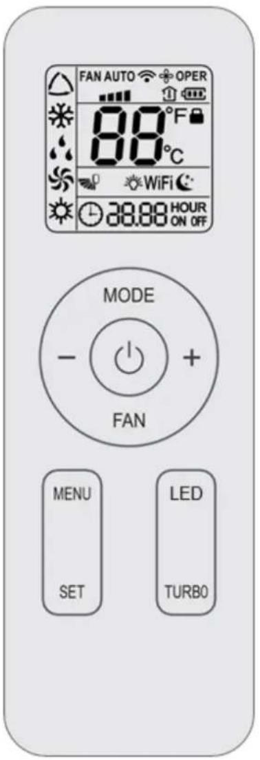
| FA A O | Set fan speed | |
| Send signal | ||
| Operation mode | △ | Auto mode |
| * | Cool mode | |
| Dry mode | ||
| Fan mode | ||
| Heat mode | ||
| Sleep mode | ||
| Light | ||
| X-FAN function | ||
| Indoor ambient temp. | ||
| Clock | ||
| 88° | Set temperature | |
| WiFi | WiFi function | |
| 88:88 | Set time | |
| ONOFF | TIMER ON / TIMER OFF | |
| Up & down swing | ||
| Child lock | ||
INSTALLATIEMETHODE VOOR MONTAGEPLAAT
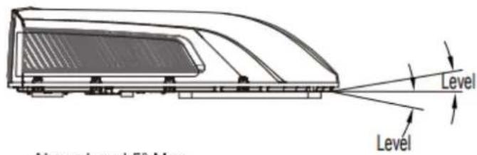
Note: Try you best to put the unit on the horizontal surface for operation. The unit can only operate for a short time at the maximum sloping angle of 5^ for preventing water leakage.
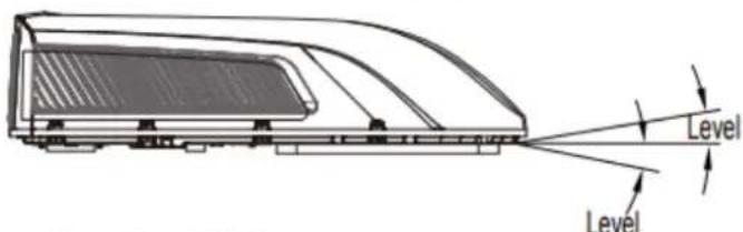
Above Level 5^ Max Below Level 0^ Max
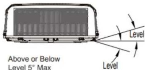
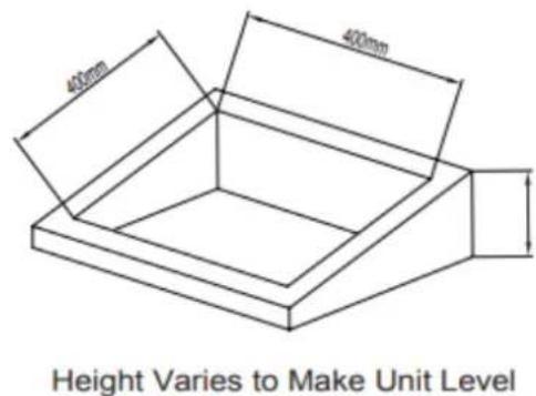
Figure 3
Opmerking: Afmetingen airconditioner (dak van unit)
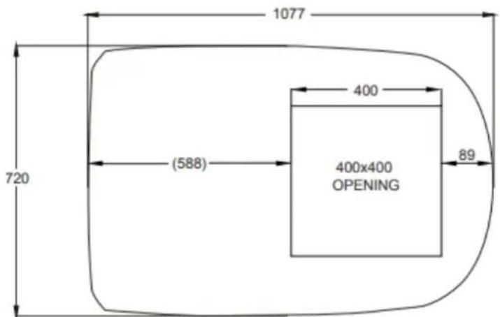
Figure 4
STAP 3 - BUITENUNIT MONTEREN
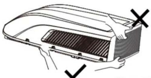
Figure 4-1
GIDS VOOR PROBLEEMOPLossing
A FEW WORDS ABOUT YOUR NEW AIR CONDITIONING UNIT 31
ELECTRICAL DATA 32
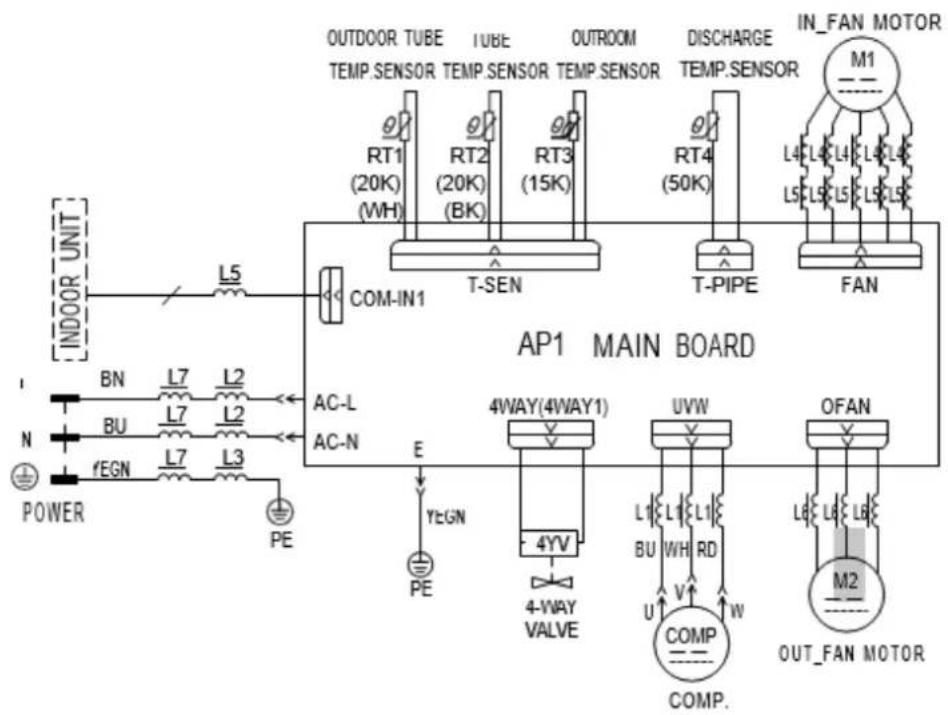
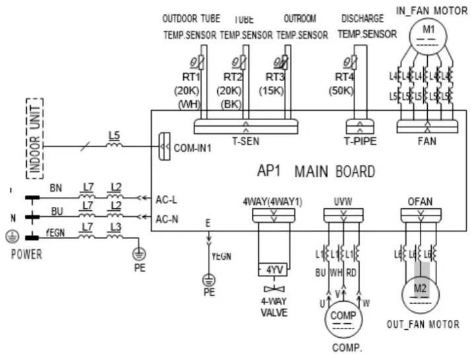
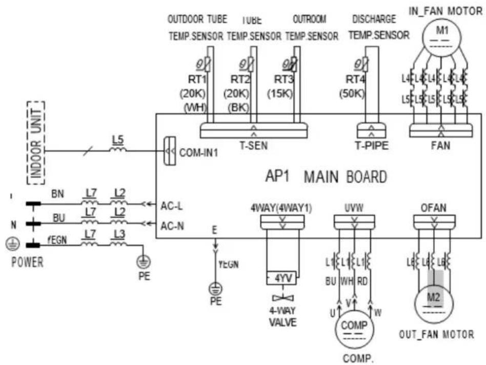
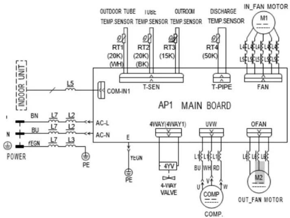
ELECTRIC DIAGRAM 33
PACKING LIST 34
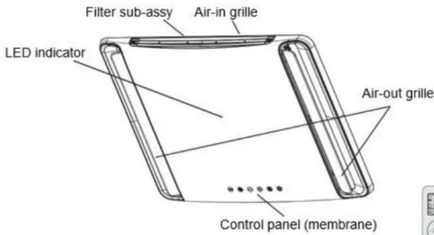
PARTS NAME 35
TROUBLESHOOTING GUIDE 48
ERROR CODE 49
NORMAL MAINTENANCE PROCEDURES 49
- This appliance is not intended for use by persons (including children) with reduced physical, sensory or mental capabilities, or lack of experience and knowledge, unless they have been given supervision or instruction concerning use of the appliance by a person responsible for their safety. Children should be supervised to ensure that they do not play with the appliance.
- This appliance can be used by children aged from 8 years and above and persons with reduced physical, sensory or mental capabilities or lack of experience and knowledge if they have been given supervision or instruction concerning use of the appliance in a safe way and understand the hazards involved.
Children shall not play with the appliance. - Cleaning and user maintenance shall not be made by children without supervision.
- When refrigerant leaks or requires discharge during installation, maintenance, or disassembly, it should be handled by certified professionals or otherwise in compliance with local laws and regulations.
Appliance filled with flammable gas R32.
Before install and use the appliance, read the owner's manual first.
Before install the appliance, read the installation manual first.

Before repair the appliance, read the service manual first.
THE REFRIGERANT
To realize the function of the unit, a special refrigerant circulates in the system. The used refrigerant is the fluoride R32, which is specially cleaned. The refrigerant is flammable and inodorous. Furthermore, it can lead to explosion under certain conditions. But the flammability of the refrigerant is very low. It can be ignited only by fire.
- Compared to common refrigerants, R32 is a nonpolluting refrigerant with no harm to the ozonosphere. The influence upon the greenhouse effect is also lower. R32 has got very good thermodynamic features which lead to a really high energy efficiency. The units therefore need a less filling.
WARNING:
- Appliance filled with flammable gas R32.
- Appliance shall be installed, operated and stored in a room with a floor area larger than 4m2
- The appliance shall be stored in a room without continuously operating ignition sources (for example: open flames, an operating gas appliance or an operating electric heater.)
- The appliance shall be stored in a well-ventilated area where the room size corresponds to the room area as specified for operation.
The appliance shall be stored so as to prevent mechanical damage from occurring. - Ducts connected to an appliance shall not contain an ignition source.
- Keep any required ventilation openings clear of obstruction.
- Do not pierce or burn.
- Be aware that refrigerants may not contain an odour.
- Do not use means to accelerate the defrosting process or to clean, other than those recommended by the manufacturer.
Servicing shall be performed only as recommended by the manufacturer. - Should repair be necessary, contact your nearest authorized Service Centre. Any repairs carried out by unqualified personnel may be dangerous.
- Compliance with national gas regulations shall be observed.
- Read specialist's manual.
INSTALLATION PRECAUTION
WARNING
- Observe all governing codes and ordinances.
- Do not use damaged or non-standard power cord.
- Be caution during installation and maintenance. Prohibit incorrect operation to prevent electric shock, casualty and other accidents.
Before turning on the unit, please open the horizontal louver of indoor unit by hand. Otherwise, the cool air can't be blown out and there will be condensate water on the horizontal louver.
Working temperature range
Suggested working temperature range: -5 46^ . (heating: -5 24^ / cooling: +18 46^ ). Outdoor unit may stop operation, due to various kinds of protection within working temperature range.
Selection of Installation Location
Basic requirement
Installing the unit in the following places may cause malfunction. If it is unavoidable, please consult the local dealer:
- The place with strong heat sources, vapors, flammable or explosive gas, or volatile objects spread in the air.
- The place with high-frequency devices (such as welding machine, medical equipment).
- The place near coast area.
- The place with oil or fumes in the air.
- The place with sulfureted gas.
- Other places with special circumstances.
- This air conditioner unit is only used for the vehicle without concave and convex surface on the top of it.
- Prohibit operating this air conditioner unit when starting up the vehicle or when the vehicle is driving.
- Prohibit supplying the power for the air conditioner unit with the vehicle power supply.
Requirement of air conditioner
- Air inlet should be far away from obstacles and do not put any objects near air outlet. Otherwise, it will affect the radiation of heat-removal pipe.
- Select a location where the noise and outflow air emitted by the outdoor unit will not affect neighborhood.
- Please try your best to keep far away from fluorescent lamp.
- The appliance shall not be installed in the laundry.
Requirements For electric Connection
Safety precaution
- Must follow the electric safety regulations when installing the unit.
- According to the local safety regulations, use qualified power supply circuit.
- For appliances with type Y attachment, the instructions shall contain the substance of the following. If the supply cord is damaged, it must be replaced by the manufacturer, its service agent or similarly qualified persons in order to avoid a hazard.
- Properly connect the live wire, neutral wire and grounding wire of power socket.
- Be sure to cut off the power supply before proceeding any work related to electricity and safety.
- Do not put through the power before finishing installation.
- The air conditioner is first class electric appliance. It must be properly grounding with specialized grounding device by a professional. Please make sure it is always grounded effectively, otherwise it may cause electric shock.
- The yellow-green wire or green wire in air conditioner is grounding wire, which can't be used for other purposes.
- The grounding resistance should comply with national electric safety regulations.
- The appliance shall be installed in accordance with national wiring regulations
- Specification of fuse on the main board:T15AH 250V; the maximum current passes through the fuse can't be more than 15A.
A FEW WORDS ABOUT YOUR NEW AIR CONDITIONING UNIT
Thank you for choosing the Recreational Vehicle Air Conditioner.
This manual will supply you with all the information for installation, operation and maintenance. Take a few minutes to discover how to get the most in cooling comfort and economic operation from your new air conditioner.
Please keep this manual well for future reference.
An all-pole disconnection switch having a contact separation of at least 3mm in all poles should be connected in fixed wiring.
Including an air switch with suitable capacity, Air switch capacity:10A.
Air switch should be included magnet buckle and heating buckle function, it can protect the circuit-short and overload.
ELECTRICAL DATA
- All wiring must be complied with local and national electrical codes. All wiring must be installed by qualified electricians. If you have any questions about the following instructions, contact a qualified electrician.
- Check the available power supply and resolve any wiring problems BEFORE installing and operating this unit.
- This air conditioner is designed to operate from a 220-240V AC, 50Hz, 1 Phase power supply.
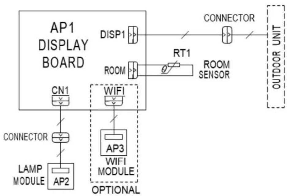
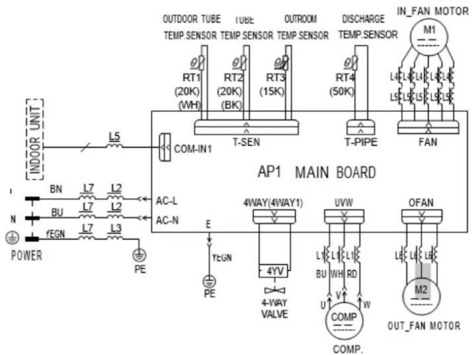
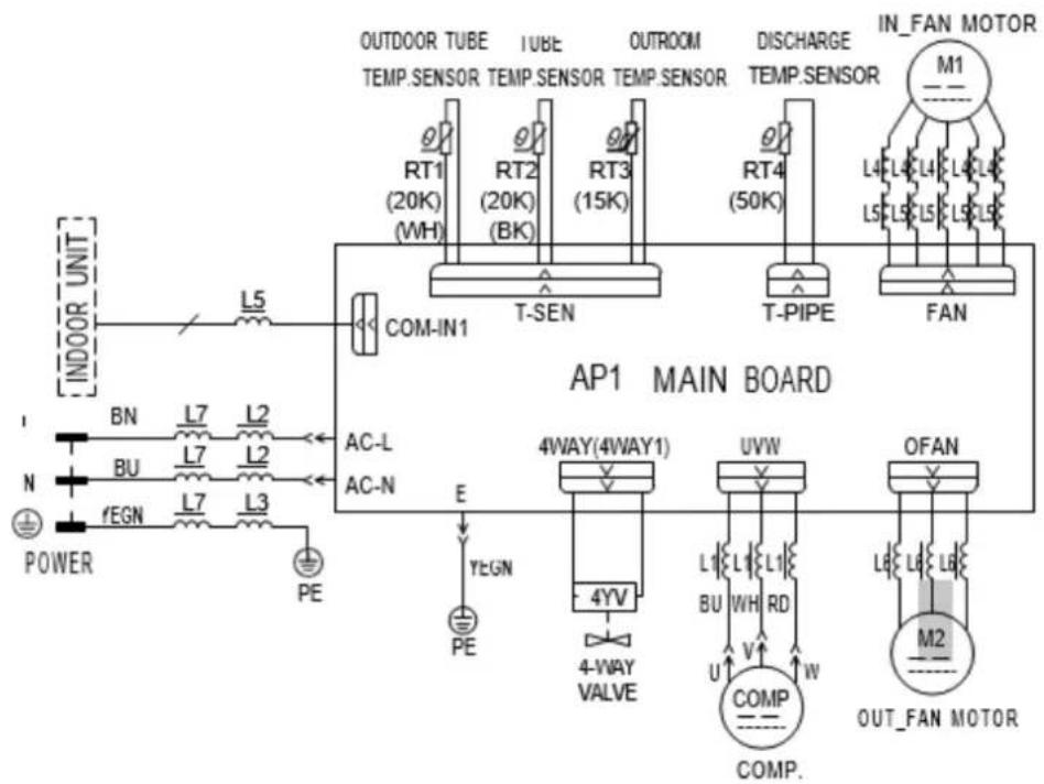
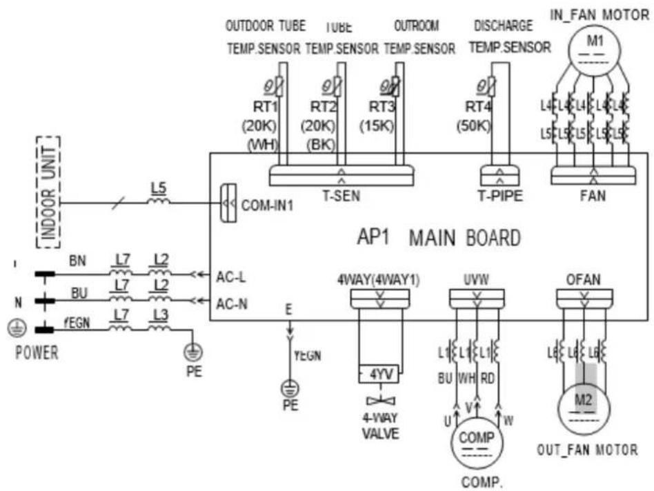
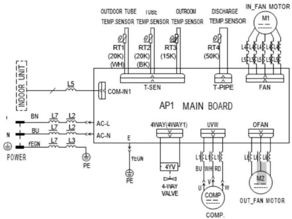
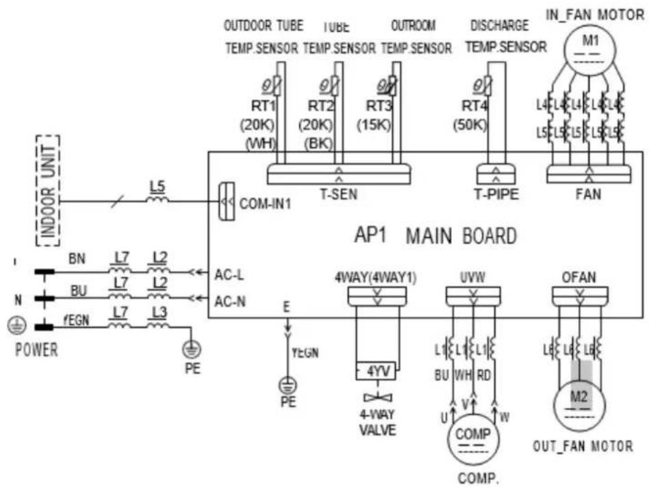
- The wiring diagrams are located on the cover of the control box. The assembly unit wire diagrams are located on the ceiling panel.
- If the supply cord is damaged, it must be replaced by the manufacturer, its service agent or similarly qualified persons in order to avoid a hazard.
- The Electric schematic diagram are subject to change without notice. Please refer to which one on the unit.
Ceiling Assembly
Roof Top Air Conditioner
PACKING LIST
| owner's manual | Mounting plate | remote controller | battery (AAA 1.5V) |
| Double-sided gummed paper | Remote controller holder | Sunk screw (remote controller holder) | foam(under) |
| Foam (accessory) | Sponge (foam accessory) | Mounting plate sub-assy | Bolt sub-assy M8X135 |
| Sponge (sealing strip) | Sponge | Insulating sheath | Bundle |
| Bolt sub-assy M6X25 | Tapping screw |
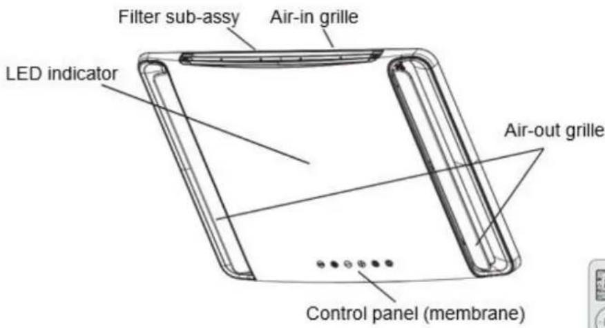
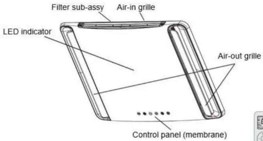
Indoor Unit
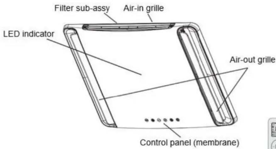
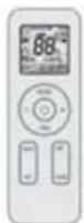
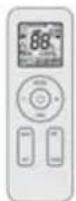
remote controller
(Display content or position may be different from above graphics, please refer to actual products)
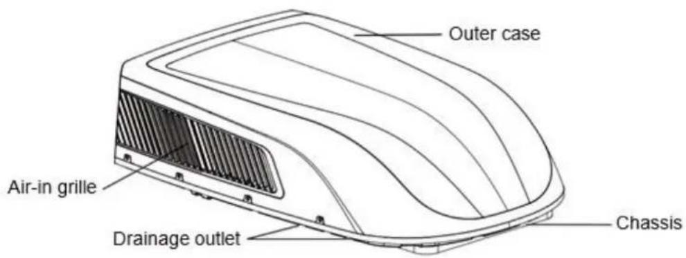
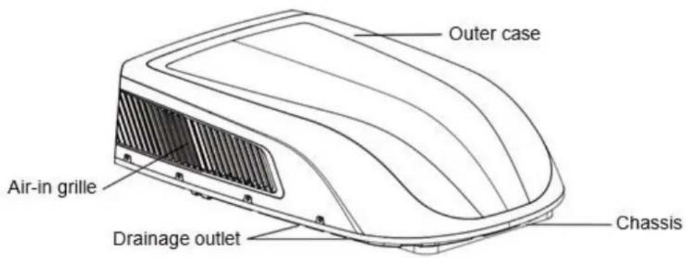
Outdoor Unit
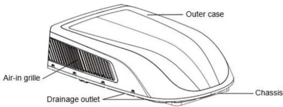
NOTICE:
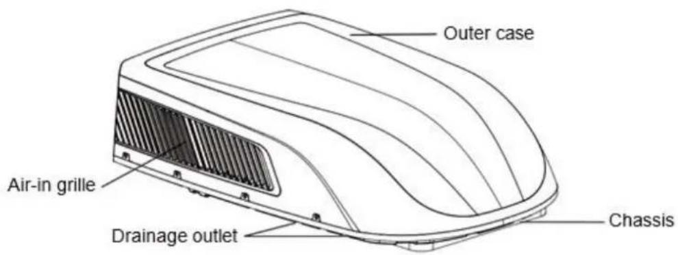
Actual product may be different from above graphics, please refer to actual products.
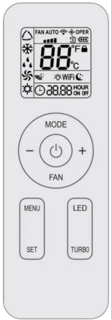
Buttons on remote controller
Introduction for icons on display screen
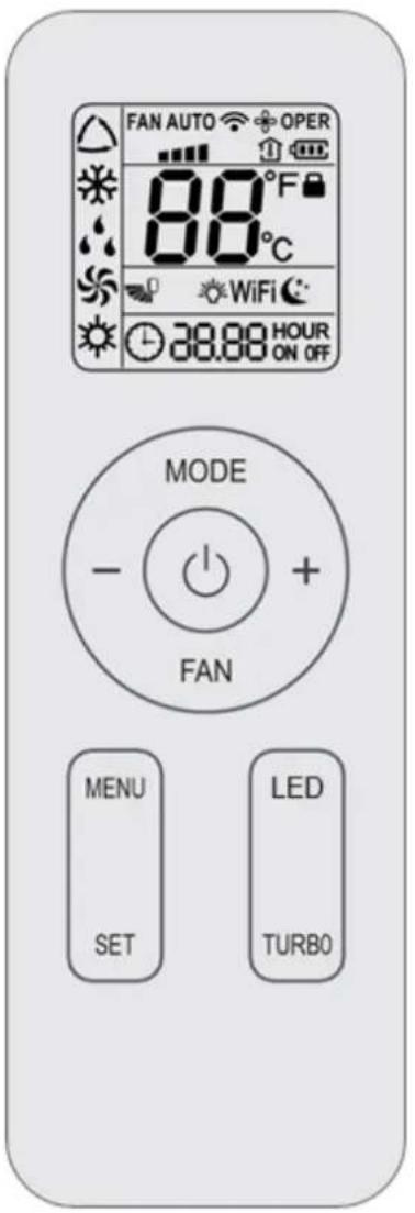
| FA A O | Set fan speed | |
| Send signal | ||
| Operation mode | △ | Auto mode |
| ※ | Cool mode | |
| ◇ | Dry mode | |
| ◇ | Fan mode | |
| Heat mode | ||
| Sleep mode | ||
| Light | ||
| X-FAN function | ||
| Indoor ambient temp. | ||
| Clock | ||
| 88° | Set temperature | |
| WiFi | WiFi function | |
| 88:88 | Set time | |
| ONOFF | TIMER ON / TIMER OFF | |
| Up & down swing | ||
| Child lock | ||
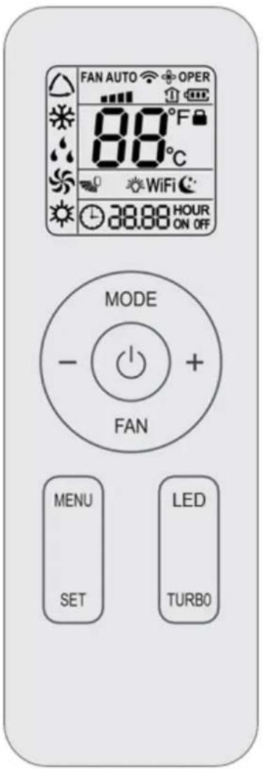
Introduction for buttons on remote controller
Note:
- This is a universal remote controller, it can be used for multifunctional air conditioners. If an air conditioner model does not have a specific function, and the corresponding button is pressed, the unit will continue running in its original status.
- After turning on the power, the air conditioner will give out a sound and the operation indicator " " is on. Now, you can operate the air conditioner through the remote controller.
- When the power is on, every time a button is pressed on the remote controller, the signal icon "..." on the remote controller will flash once. The air conditioner will give out a sound, which indicates the signal has been sent to the air conditioner.
On/off button
Press this button to turn the air conditioner on. Press this button again to turn the air conditioner off.
Mode button
- Press this button to select your required operation mode.

- In "AUTO" mode, the air conditioner will automatically operate according to the ambient temperature. The set temperature cannot be changed and will not be displayed. By pressing the "FAN" button, the fan speed can be adjusted.
- In "COOL" mode, press the "+" or "-" button to change the set temperature. To adjust the fan speed, press the "FAN" button.
- In "DRY" mode, the air conditioner operates at low speed. The fan speed cannot be adjusted.
- In "FAN" mode, only the fan is turned on, without any cooling or heating. Press the "FAN" button, to adjust the fan speed.
- In "HEAT" mode, press the "+" or "-" button to change the set temperature. To adjust the fan speed, press the "FAN" button.
Note:
After the "HEAT" mode is selected, the air conditioner will delay air blowing 1-5 minutes, to prevent blowing cold air. (The actual delay time depends on the indoor ambient temperature.)
The temperature can be set between 16 - 30^ (61 - 86^)
- This mode indicator is not available for some models.
Cooling only unit won't receive heat mode signal. If setting heat mode with remote controller, press " button can't start up the unit.
Fan button
This button is used for setting the fan speed in the following sequence:
AUTO, , , , , , then back to Auto.
Note:
Fan speed "■■" is unavailable for some models,
Fan speed "the same with fan speed" for some models.
- In "AUTO" speed mode, the air conditioner will automatically select the proper fan speed according to the default setting.
- AUTO speed is only available for some models.
- In "DRY" mode, the fan speed is low.
- "X-FAN" function: when the "FAN" button is pressed for 2 seconds in "COOL" or "DRY" mode, the icon " 品 " is displayed and the indoor fan will continue operation for a few minutes in order to dry the indoor unit, even when the unit is turned off. If the "FAN" button is now pressed for 2 seconds, the fan will stop
immediately. "X-FAN" is not available in auto, fan or heat mode. This function indicates that moisture on evaporator of indoor unit will be blown after the unit is stopped to avoid mould.
- Having set X-FAN function on: After turning off the unit by pressing " " button, indoor fan will continue running for a few minutes at low speed. In this period, hold fan speed button for 2s to stop indoor fan directly. Having set X-FAN function off: After turning off the unit by pressing " " button, the complete unit will be off directly.
- X-FAN function is only available for some models.
-/+button
- Press the "+" or "-" button once to increase or decrease the set temperature by 1^(^ F) . Hold the "+" or "-" button down for at least 2 seconds, and the set temperature will change quickly. Once the "+" or "-" button is released after setting the temperature, the temperature indicator on the air conditioner will change accordingly. The temperature cannot be adjusted in "AUTO" mode.
- When setting the "TIMER ON" or the "TIMER OFF" or the "CLOCK", press the "+" or "-" button to adjust the time. Look for more information under 'Timer on function', 'Timer off function', or 'Clock function'.
Menu button
- Press this button to select the desired submenu and press the "SET" button to set the function status of the submenu. The submenu can be selected circularly as follows:
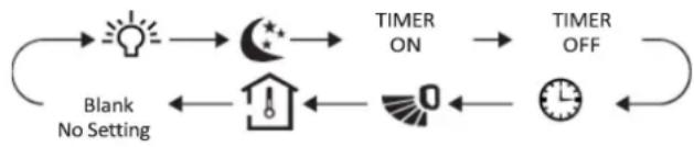
NOTE
Some menu's function may be unavailable under different models.

Light function
When selecting light function, light icon " 品 " flashes for 5s; press "SET" button within 5s to turn off display light on indoor unit and " 品 " icon on remote controller disappears. Press "SET" button again within 5s to turn on display light and " 品 " icon is displayed.

Sleep function
When selecting sleep function, sleep icon "C" flashes for 5s; press "SET" button within 5s to turn on sleep function and "C" icon is displayed on remote controller. Press "SET" button again within 5s to turn off sleep function and "C" icon disappears.

up & down swing function
Not available for this unit.

Ambient temperature display function
When selecting ambient temperature display function, icon " " flashes for 5s; press "SET" button within 5s to select ambient temperature display on or off. After setting " " function on, the " " icon will be displayed on remote controller and you can see indoor ambient temperature on indoor unit's displayer for a few seconds.
TIMER ON function
TIMER ON function can set the time for timer on. Under TIMER ON function status," icon disappears and the word "ON" on remote controller blinks. Press "+" or "-" button to adjust TIMER ON setting. After each
pressing "+" or "-" button TIMER ON setting will increase or decrease 1min. Hold "+" or "-" button, 2s later, the time will change quickly until reaching your required time. Press "SET" button to confirm it within 5S. The word "ON" will stop blinking. Cancel TIMER ON: Press "MENU" button to TIMER ON function and the characters "ON" flashes on the remote controller; press "SET" button until the characters "ON" disappears.
TIMER OFF function
TIMER OFF function can set the time for timer off. Under TIMER OFF function status," " icon disappears and the word "OFF" on remote controller blinks. Press "+" or "-" button to adjust TIMER OFF setting. After each pressing "+" or "-" button TIMER OFF setting will increase or decrease 1min. Hold "+" or "-" button, 2s later, the time will change quickly until reaching your required time, press "SET" button to confirm it within 5S. The word "OFF" will stop blinking.
Cancel TIMER OFF: Press "MENU" button to TIMER OFF function and the characters "OFF" flashes on the remote controller; press "SET" button until the characters "OFF" disappears
CLOCK function
CLOCK function can set clock time. Under CLOCK function status, " 心 " icon on remote con- troller will blink. Press "+" or "-" button within 5s to set clock time. Each pressing of "+" or "-" button, clock time will increase or decrease 1 min. If hold "+" or "-" button, 2s later, time will change quickly. Release this button when reaching your required time, press "SET" button to confirm it within 5S. The " 心 " icon will stop blinking.
LED button
Press this button can turn on or turn off the LED light on the panel.
TURBO button
Under COOL or HEAT mode, press this button to turn to quick COOL or quick HEAT mode." n is displayed on remote controller. If start this function, the unit will run at super-high fan speed to cool or heat quickly so that the ambient temperature approaches the preset temperature as soon as possible.
Note
Fan Speed " is unavailable for some models.
- Fan Speed "■■" is the same with Fan Speed "■■" for some models
Function introduction for combination buttons
Child lock function
Press "+" and "-" simultaneously to turn on or turn off child lock function. When child lock function is on, " " icon is displayed on remote controller. If you operate the remote controller, the " " icon will blink three times without sending signal to the unit.
Temperature display switchover function
Under OFF status, press " - " and "MODE" buttons simultaneously to switch temperature display between ^ C and ^ F .
WiFi function
Press "MODE" and "TURBO" button simultaneously to turn on or turn off WiFi function. When WiFi function is turned on, the "WiFi" icon will be displayed on remote controller; Long press "MODE" and "TURBO" buttons simultaneously for 10s, remote controller will send WiFi reset code and then the WiFi function will be turned on. WiFi function is defaulted ON after energization of the remote controller.
Note
- This function is only available for some models
Replacement of batteries in remote controller
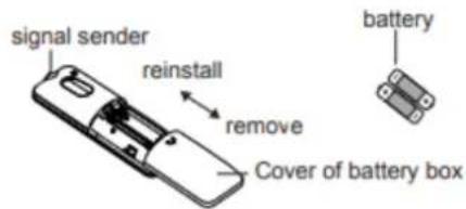
- Press the back side of remote controller marked with " 念 as shown in the fig, and then push out the cover of battery box along the arrow direction.
- Replace two 7# (AAA 1.5V) dry batteries, and make sure the position of "+" polar and "-" polar are correct.
- Reinstall the cover of battery box
Notice
During operation, point the remote control signal sender at the receiving window on indoor unit.
The distance between signal sender and receiving window should be no more than 8m and there should be no obstacles between them.
- Signal may be interfered easily in the room where there is fluorescent lamp or wireless telephone; remote controller should be close to indoor unit during operation.
- Replace new batteries of the same model when replacement is required.
- When you don't use remote controller for a long time, please take out the batteries.
If the display on remote controller is fuzzy or there's no display, please replace batteries.
CONTROL PANEL
Note: If the remote controller is missing, operate on the control panel.
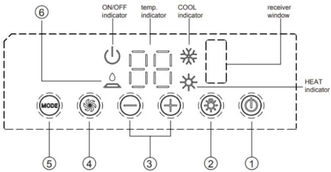
- ON/OFF button
Operation starts when pressing this button, and stops when pressing this button again
- LIGHT button
Press this button to turn on or turn off display light on indoor unit
- (+ / -) button
Press the + button to increase the set (operating) temperature of the unit, and press the - button to decrease the set (operating) temperature of the unit. The temperature setting range is from 16 30^ (61 86F)
- FAN SPEED button
Select the fan speed LOW, MED, HIGH and TURBO (This function is applicable to partial of models) in sequence.
- MODE button
Select the operation mode, COOL, FAN, HEAT
- FILTER CHECK indicator
This feature is a reminder of cleaning the air filter (normal maintenance) for more efficient operation. The light will turn on automatically after the fan works more than 250 hours. If the light is on, turn off and power off the unit, take the air filter out and clean it, then re-install the air filter, power on and turn on the unit, the light will still be on, press + button for 5s, the light will turn off
INSTALLATION INSTRUCTIONS
BEFORE INSTALLATION
Test run the unit with proper power supply. Refer to the operation instruction section in the Owner's Manual Operation & Installation. Make sure all the controls operate correctly then disconnect the power supply of the unit.
WARNING
- Moving parts may cause personal injury. Be careful when test the unit. Do not operate the unit with exterior cover removed.
- Outdoor unit can't be installed at the low recess of the roof of vehicle. It must be mounted at the flat surface on the roof of vehicle to make sure the rain, car-washing water, condensate water, etc. can be drained smoothly. No water is allowed to be accumulated around the outdoor unit; otherwise, it will cause malfunction or safety hazards as the water will pour into the air conditioner.
- Please use the equipped mounting Plate for installation; otherwise, it may cause malfunction or damage.
STEP 1 - STICK SponGE (SEALING STRIP) AND SponGE ON THE OUTDOOR UNIT
- Before sticking, clean up the sundries at the sticking position (as shown in Figure 1) of the chassis of the outdoor unit to ensure that the sticking position is clean;
- Take out one piece of sponge (sealing strip) and five pieces of sponge from the accessories, and tear off the paper on the glue surface and align at the edge of the position as shown in Figure 1 to stick the sponge. If the sponge (sealing strip) is damaged or not stuck on the proper position, you must replace it with a new one and stick it properly:
- Check whether the sponge (sealing strip) and the sponge are tightly adhered, and ensure that they will not fall off.
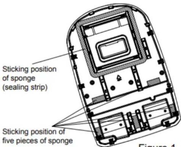
Figure 1
STEP 2 - SELECTING AN INSTALLATION LOCATION & INSTALLING THE ROOF TOP AIR CONDITIONER
Your air conditioner has been designed for use in recreational vehicles.
Check the roof of the vehicle to determine if it can support both the roof top unit and the ceiling assembly without additional support. Make sure the interior ceiling mounting area will not interfere with existing structures.
Once the location for your air conditioner has been determined. A reinforced and framed roof. Hole must be cut (if there is no hole, please refer to CASE B) or you may use existing vent holes (See CASE A)
CASE A.
If a roof vent is already present in the desired mounting location for the air conditioner the following steps must be performed:
- Remove all screws which secure the roof vent to the vehicle. Remove the vent and any additional trim. Carefully remove all chalking from around the opening so the surface is clear.
- It may be necessary to seal some of the old roof vent mounting screw holes which may fall outside of the air conditioner basepan gasket.
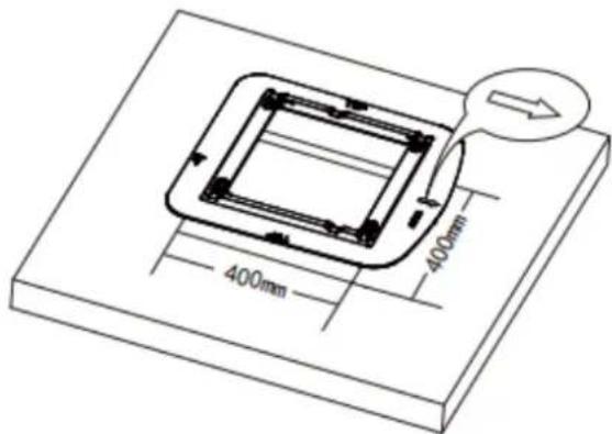
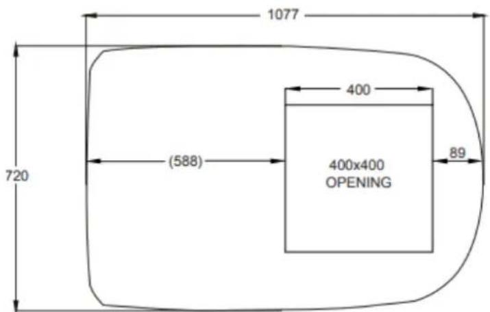
- Examine the roof opening size, if the opening is small than 400 × 400 ~mm , the opening must be enlarged
CASE B.
If a roof vent opening is not used, a new opening (see figure 1-1) will be cut into the vehicle roof. A matching opening will also have to be cut into the interior vehicle ceiling, be careful when cutting the ceiling opening because if the ceiling opening is carpeted, snagging could occur. After the opening in the roof and interior ceiling are the correct size, a framed support structure must be placed between the exterior roof top and interior ceiling. The reinforced framed structure must follow the following guidelines:
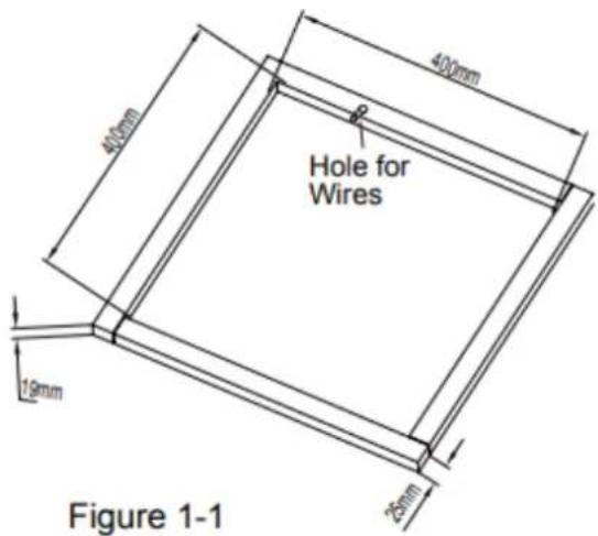
- It must be capable of supporting both the weight of the roof top air conditioner and the interior ceiling assembly
- It must be capable of holding the roof outer surface and interior ceiling apart and supporting them, so that when the roof top air conditioner and ceiling assembly are bolted together, no collapsing occurs. A typical support frame is shown in Figure 1-1
- There must be an opening through the frame for the power supply wiring. Route the supply wiring through the frame at the same time the support frame is being installed.
INSTALLATION METHOD FOR MOUNTING PLATE
If the roof already has a 400 × 400 ~mm opening. Select the installation position for the recreational vehicle air conditioner This mounting plate of switchover opening is applicable for Gree recreational vehicle air conditioner. The opening size of installation port on the top of the vehicle must be 400 × 400 ~mm .
Operation method:
-
Eliminate the sundries around the installation port on the top of the vehicle and keep the installation surface flat;
-
Check whether there are holes or grooves on surface of installation position. If yes, conduct the sealing treatment to prevent water leakage;
- Fill the groove on the surface where the mounting plate is contacting the top part of the vehicle with the unhardened sealant (the maximum thickness is 1cm); When the mounting plate is installed on the top of vehicle, fill the sealant in the gap between the mounting plate and the vehicle roof. The mounting plate should be tightly sealed with the roof of the vehicle to prevent water leakage.
- Install it into the opening on the top of the vehicle according to the indicate direction by the arrow (the direction of arrow should be the same with the head of the vehicle).
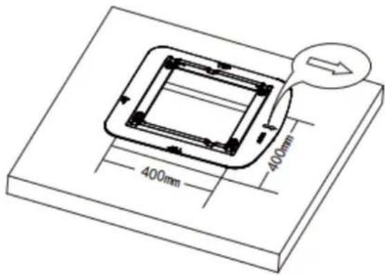
Figure 1-2
CAUTION
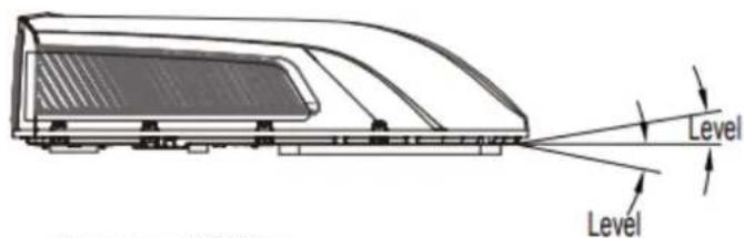
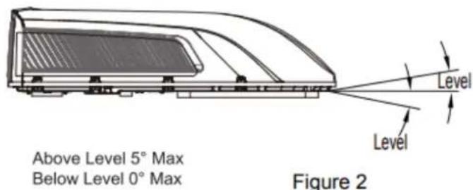
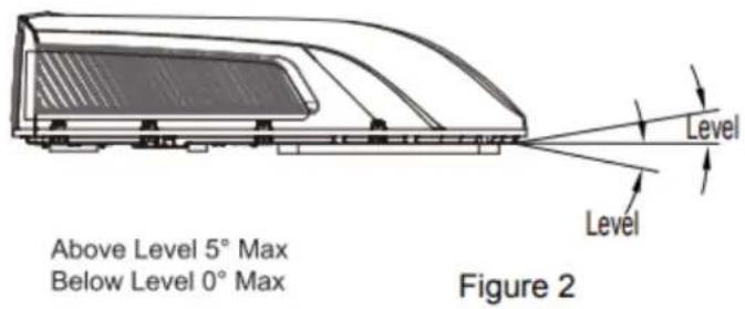
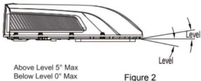
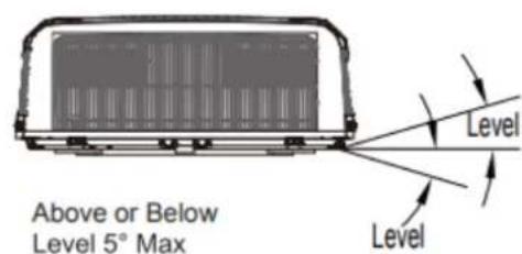
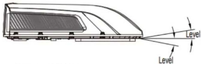
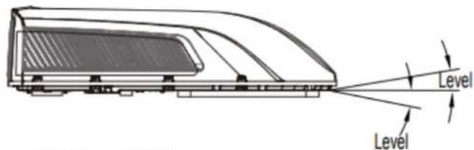
- The roof top air conditioner must be mounted on a level plane from front to rear and side to side when the vehicle is parked on a level plane. Figure 2 shows maximum allowable degrees that the unit can be mounted above or below level.
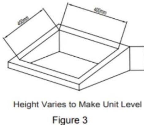
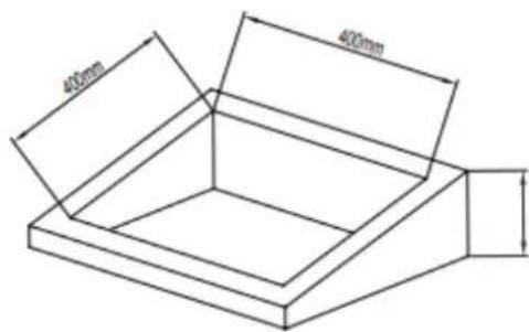
- If the roof of the vehicle is sloped (not level) such that the roof top air conditioner cannot be mounted within the maximum allowable degree specifications, an exterior leveling shim will need to be added to make the unit level. A typical leveling shim is shown in Figure 3.
- Once the roof top air conditioner has been leveled, some additional shimming may be required above the interior ceiling assembly. The roof top air conditioner and the interior ceiling assembly must be square with each other before they are secured together.
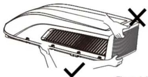
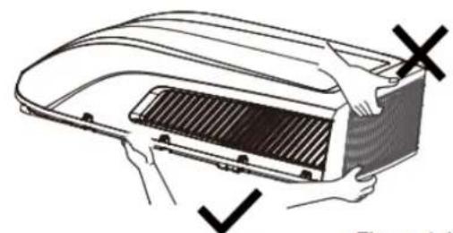
- After the mounting hole area is properly prepared, remove the carton and shipping pads from around the roof top air conditioner. Carefully lift the unit on top of the vehicle. Do not use the outer plastic shroud for lifting. Place the roof top air conditioner over the prepared mounting hole.
- The front section of outdoor unit of air conditioner must be in the same direction as the vehicle, which is useful for reducing wind resistance.
Note: Try you best to put the unit on the horizontal surface for operation. The unit can only operate for a short time at the maximum sloping angle of 5^ for preventing water leakage.
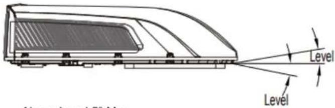
Above Level 5^ Max Below Level 0^ Max
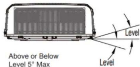
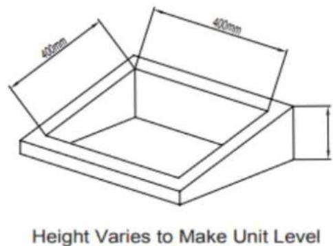
Figure 3
Note: Air conditioner dimensions (roof of unit)
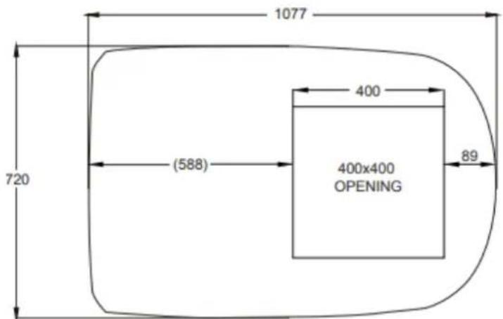
Figure 4
STEP3-MOUNTINGOUTDOORUNIT
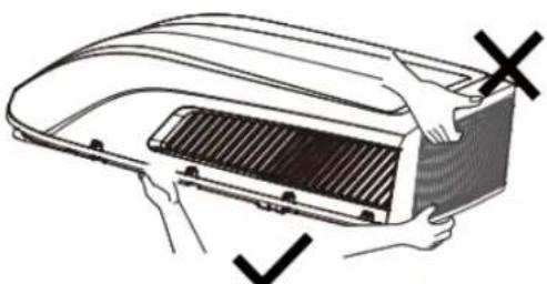
Figure 4-1
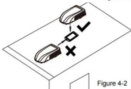
- Open the package and take out the outdoor unit a) When taking out the outdoor unit after unpacking, do not lift the air outlet grille at the back of outer case (see Figure 4-1).
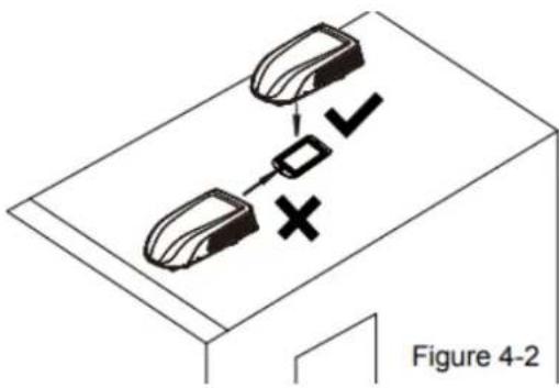
- Put the outdoor unit at the mounting plate of switchover opening.
a) Lift the outdoor unit. During the movement, it is strictly forbidden to hoist the plastic outer casing of outer unit of the air conditioner.
b) Put it on the mounting plate of the prepared switchover opening to make the sealing strip of outdoor unit match with the groove on the surface of the mounting plate. Do not drag the outdoor unit. Otherwise, the seal may fall off.
STEP4-INSTALLING THE CEILING ASSEMBLY
Make sure that you have properly matched the roof top air conditioner and interior ceiling assembly. Caution before tightening bolts:
- The applicable thickness of vehicle roof ranges from 30mm 80mm
- Before tightening bolts, screw in the four bolts manually and prohibit screwing forcibly.
- When screwing bolts, you can use automatic tool. Do not tighten one bolt completely and then tighten other bolts, in order to prevent sticking of screw thread.
- The max torque for tightening ranges from 2.3Nm 2.5Nm
The following step by step instructions must be performed in the following sequence to ensure proper
- Carefully take the ceiling assembly out of the carton.
- Remove the ceiling grille from the ceiling assembly.
- Then carry the outdoor unit to the vehicle's top and align with the openings on the vehicle's top. Use 2 sets of mounting plate assembly and 4 screw bolts to mount the outdoor unit. As for installing the mounting plate sub-assy, these 4 long bolts' holes should be align with the 4 holes on the adaptor respectively at first and then the upper planes on the bottom edge of two mounting plates must be overlapped with the bottom surface of vehicle roof. (See Figure 5).
- You must start (thread) the mounting bolts by hand to avoid cross-threading. DO NOT START THE MOUNTING BOLTS WITH AN AIR GUN. The mounting bolts should be tightened, process is completed when the basepan gasket has been evenly compressed.
- Before installing the air duct assembly of the indoor unit of recreational vehicle air conditioner, assemble the foam assembly according to the thickness of the vehicle's top. After simulated installation, use an appropriate amount of sponge and foam assembly. Stick the sponge and foam assembly with double faced adhesive tape (prepared by user) (See Figure 5-1, Figure 5-2)
- Install the foam assembly on the air duct assembly. Use 4 screw bolts to fix the air duct assembly onto the mounting plate. After connecting the outdoor unit with indoor unit, check whether the foam assembly has come loose (See Figure 5).

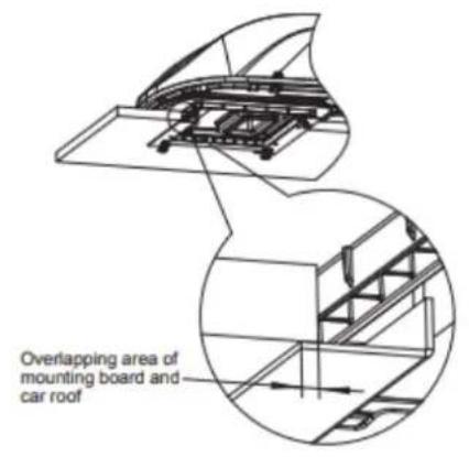
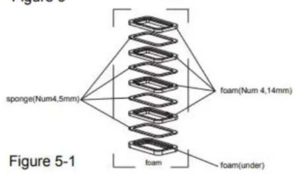

Figure 5-2
STEP5-ELECTRICAL WIRING
ROUTING 220-240V AC WIRING
WARNING
Make sure that all power supply to the unit is disconnected before performing any work on the unit to avoid the possibility of shock or injury and/or damage to the equipment. When the interior ceiling assembly frame is properly secured to the roof top air conditioner, the following electrical connections must be performed.
- As shown in Figure 6, the outdoor unit has two sets of outgoing wires, which are power cord (high current) and the control signal wires respectively. The former one should be directly connected to the power supply terminal while the latter one should be connected to the control signal wire of the indoor unit.
- As shown in Figure 7, the indoor unit has one set of control signal wires, with 1 wiring terminals in total.
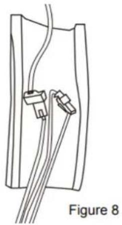
- Connect the docking terminals of indoor unit and outdoor unit, see Figure 8.
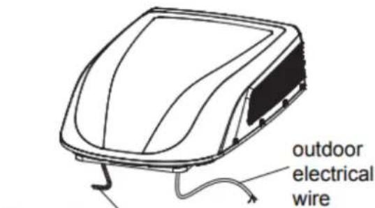
Figure 6 outdoor connect wire
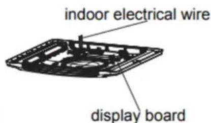
Figure 7
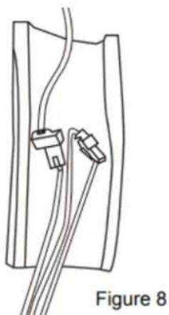
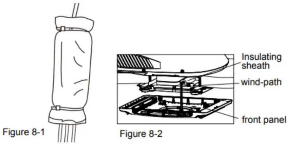
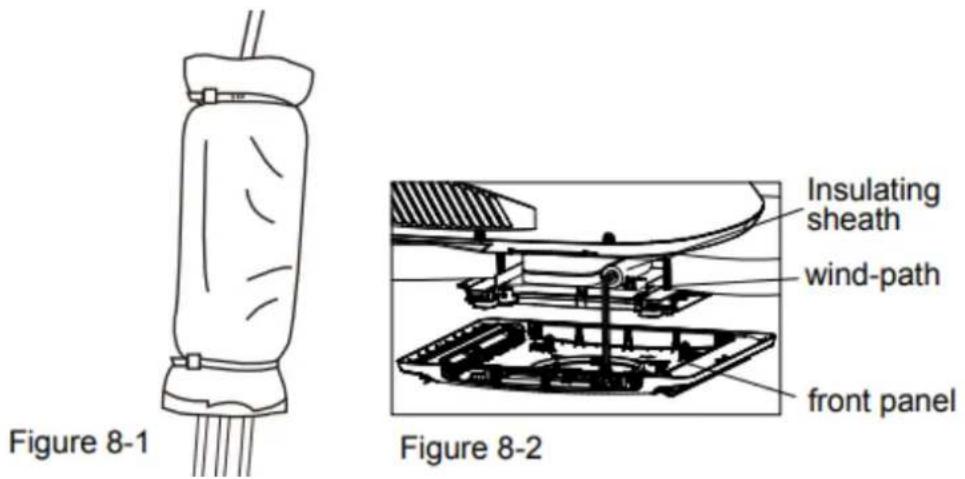
- Use protective sleeve to wrap the wiring terminal, stick the protective sleeve and then use cable tie to bundle them tightly
Note:
- The fixing position of cable must be at both ends of wiring terminal.
- Before installing the front panel of indoor unit, put the thermal insulating jacket on top of the air duct.
STEP 6 - COMPLETING THE INSTALLATION
To complete the installation and system checkout requirements, the following steps must be performed
- Check the thermostat position. Make sure the thermostat is routed through the holding guide and is not touching any metal surface.
- Secure the ceiling grille to the ceiling assembly wind-path with 4 screws. (see Figure 9).
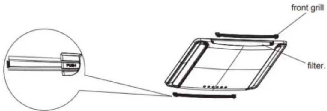
- Install the healthy filter and air intake grill. Press "PUSH" and lock with clasps.
- Switch on the power supply and check the unit work or not.
- Once the indoor unit is assembled, if the gap between the panel and the top of vehicle is not even, please ask the manufacturer to adjust it according to the assembly status

TROUBLESHOOTING GUIDE
If you have problems with your recreational vehicle air conditioner, check this guide before contacting your service representative.
| Trouble | Possible cause | Solution |
| The unit can not start | The unit may not be connected to the power supply correctly | Check the power supply of the vehicle and make sure it is provided correctly |
| The unit can not cool the room | The roof top air conditioner is not level.The temperature setting is too high.The air filter is dirty.The room was already very hot before the unit was turned on. | Mount the roof top air conditioner as level as possible from front to rear and side to side when the vehicle is parked.Make sure that the mounting of the air conditioner is correct and levelReset the remote control to a lower temperature setting.Remove and clean the filterAllow a sufficient amount of time for unit to cool the room. |
| The unit is making noise | The unit is click and gurgle. | These noise are normal during the operation of the unit. |
| The unit has water dripping inside | The basepan gasket has not been evenly compressed. | Mounting bolts should be tightened evenly by compressing the basepan gasket. |
| The unit has ice or frost on the coils | The temperature is low inside.The filter is dirty. | Select FAN mode at HIGH fan speed.Remove and clean the filter |
ERROR CODE
When the air conditioner is abnormal, error codes (they can't disappear even after re-energization) will be displayed on the air conditioner: C^, E^, F^, H^, L^, P^, U^, J^, e^ ("" represents numbers or letters) except the functional display code introduced in the owners' manual. Please turn off the unit and contact Gree appointed maintenance center
NORMAL MAINTENANCE PROCEDURES
| Activity | Frequency |
| Remove the cover and wash the condenser coil | Twice a year. |
| Clean the filter (More frequent cleaning may be necessary depending on the air quality) | When the air conditioner FILTER CHECK light on |
HOW TO REMOVE THE AIR FILTER
Push both sides of the air intake grill on the positions marked with "PUSH". Open the air intake grill and then take out the healthy filter.
HOW TO CLEAN THE AIR FILTER
Wash away dust from the air filters with clean water or vacuum the filter with an electric household vacuum cleaner.
WARNING
FAILURE TO FOLLOWING INSTRUCTIONS COULD RESULT IN SERIOUS PERSONAL INJURY
- Don't touch the capacitor terminals without the electric discharge, the capacitor still may have the high voltage even though the power supply is turned off
- Be careful when you maintain the refrigeration system, which has the high internal pressure.
- Do not block the filter and the indoor air inlet badly to prevent water leakage.
SPECIALIST'S MANUAL
Aptitude requirement for maintenance man (repairs should be done only be specialists).
- Any person who is involved with working on or breaking into a refrigerant circuit should hold a current valid certificate from an industry-accredited assessment authority, which authorises their competence to handle refrigerants safely in accordance with an industry recognised assessment specification.
- Servicing shall only be performed as recommended by the equipment manufacturer. Maintenance and repair requiring the assistance of other skilled personnel shall be carried out under the supervision of the person competent in the use of flammable refrigerants.
Safety preparation work
The maximum refrigerant charge amount is shown on the following table
(Note: Please refer to the nameplate for the charging quantity of R32).
| Room area (m2) | / | 4 | 7 | 10 | 15 |
| Maximum charge (kg) | <1.224 | 2.50 | 3.31 | 3.96 | 4.85 |
Prior to beginning work on systems containing flammable refrigerants, safety checks are necessary to ensure that the risk of ignition is minimised. For repair to the refrigerating system, the following precautions shall be complied with prior to conducting work on the system.
- Work procedure
Work shall be undertaken under a controlled procedure so as to minimise the risk of a flammable gas or vapour being present while the work is being performed.
- General work area
All maintenance staff and others working in the local area shall be instructed on the nature of work being carried out. Work in confined spaces shall be avoided. The area around the workspace shall be sectioned off. Ensure that the conditions within the area have been made safe by control of flammable material
- Checking for presence of refrigerant
The area shall be checked with an appropriate refrigerant detector prior to and during work, to ensure the technician is aware of potentially toxic or flammable atmospheres. Ensure that the leak detection equipment being used is suitable for use with all applicable refrigerants, i.e. non-sparking, adequately sealed or intrinsically safe.
Presence of fire extinguisher
If any hot work is to be conducted on the refrigeration equipment or any associated parts, appropriate fire extinguishing equipment shall be available to hand. Have a dry powder or CO2 fire extinguisher adjacent to the charging area.
- No ignition sources
No person carrying out work in relation to a refrigeration system which involves exposing any pipe work shall use any sources of ignition in such a manner that it may lead to the risk of fire or explosion. All possible ignition sources, including cigarette smoking, should be kept sufficiently far away from the site of installation, repairing, removing and disposal, during which refrigerant can possibly be released to the surrounding space. Prior to work taking place, the area around the equipment is to be surveyed to make sure that there are no flammable hazards or ignition risks. "NO Smoking" signs shall be displayed
- Ventilated area
Ensure that the area is in the open or that it is adequately ventilated before breaking into the system or conducting any hot work. A degree of ventilation shall continue during the period that the work is carried out. The ventilation should safely disperse any released refrigerant and preferably expel it externally into the atmosphere.
- Checks to the refrigeration equipment
Where electrical components are being changed, they shall be fit for the purpose and to the correct specification. At all times the manufacturer's maintenance and service guidelines shall be followed. If in doubt, consult the manufacturer's technical department for assistance
The following checks shall be applied to installations using flammable refrigerants:
- The actual refrigerant charge is in accordance with the room size within which the refrigerant containing parts are installed;
- The ventilation machinery and outlets are operating adequately and are not obstructed;
If an indirect refrigerating circuit is being used, the secondary circuit shall be checked for the presence of refrigerant; - Marking to the equipment continues to be visible and legible. Markings and signs that are illegible shall be corrected;
- Refrigeration pipe or components are installed in a position where they are unlikely to be exposed to any substance which may corrode refrigerant containing components, unless the components are constructed of materials which are inherently resistant to being corroded or are suitably protected against being so corroded.
- Checks to electrical devices
Repair and maintenance to electrical components shall include initial safety checks and component inspection procedures. If a fault exists that could compromise safety, then no electrical supply shall be connected to the circuit until it is satisfactorily dealt with. If the fault cannot be corrected immediately but it is necessary to continue operation, an adequate temporary solution shall be used. This shall be reported to the owner of the equipment so all parties are advised.
Initial safety checks shall include:
- That capacitors are discharged: this shall be done in a safe manner to avoid possibility of sparking;
- That no live electrical components and wiring are exposed while charging, recovering or purging the system;
- That there is continuity of earth bonding.
Repairs to sealed components
During repairs to sealed components, all electrical supplies shall be disconnected from the equipment being worked upon prior to any removal of sealed covers, etc. If it is absolutely necessary to have an electrical supply to equipment during servicing, then a permanently operating form of leak detection shall be located at the most critical point to warn of a potentially hazardous situation.
Particular attention shall be paid to the following to ensure that by working on electrical components, the casing is not altered in such a way that the level of protection is affected. This shall include damage to cables, excessive number of connections, terminals not made to original specification, damage to seals, incorrect fitting of glands, etc
- Ensure that the apparatus is mounted securely.
- Ensure that seals or sealing materials have not degraded to the point that they no longer serve the purpose of preventing the ingress of flammable atmospheres. Replacement parts shall be in accordance with the manufacturer's specifications.
NOTE : The use of silicon sealant can inhibit the effectiveness of some types of leak detection equipment. Intrinsically safe components do not have to be isolated prior to working on them.
Repair to intrinsically safe components
Do not apply any permanent inductive or capacitance loads to the circuit without ensuring that this will not exceed the permissible voltage and current permitted for the equipment in use.
Intrinsically safe components are the only types that can be worked on while live in the presence of a flammable atmosphere. The test apparatus shall be at the correct rating.
Replace components only with parts specified by the manufacturer. Other parts may result in the ignition of refrigerant in the atmosphere from a leak.
Cabling
Check that cabling will not be subject to wear, corrosion, excessive pressure, vibration, sharp edges or any other adverse environmental effects. The check shall also take into account the effects of aging or continual vibration from sources such as compressors or fans.
Detection of flammable refrigerants
Under no circumstances shall potential sources of ignition be used in the searching for or detection of refrigerant leaks. A halide torch (or any other detector using a naked flame) shall not be used.
Leak detection methods
The following leak detection methods are deemed acceptable for all refrigerant systems.
Electronic leak detectors may be used to detect refrigerant leaks but, in the case of flammable refrigerants, the sensitivity may not be adequate, or may need re-calibration. (Detection equipment shall be calibrated in a refrigerant-free area.) Ensure that the detector is not a potential source of ignition and is suitable for the refrigerant used. Leak detection equipment shall be set at a percentage of the LFL of the refrigerant and shall be calibrated to the refrigerant employed, and the appropriate percentage of gas (25% maximum) is confirmed. Leak detection fluids are suitable for use with most refrigerants but the use of detergents containing chlorine shall be avoided as the chlorine may react with the refrigerant and corrode the copper pipe-work.
If a leak is suspected, all naked flames shall be removed/extinguished.
If a leakage of refrigerant is found which requires brazing, all of the refrigerant shall be recovered from the system, or isolated (by means of shut off valves) in a part of the system remote from the leak. For appliances containing flammable refrigerants, oxygen free nitrogen (OFN) shall then be purged through the system both before and during the brazing process
Removal and evacuation
When breaking into the refrigerant circuit to make repairs - or for any other purpose - conventional procedures shall be used. However, for flammable refrigerants it is important that best practice is followed since flammability is a consideration. The following procedure shall be adhered to:
- remove refrigerant;
purge the circuit with inert gas; evacuate;
purge again with inert gas;
- open the circuit by cutting or brazing.
The refrigerant charge shall be recovered into the correct recovery cylinders. For appliances containing flammable refrigerants, the system shall be "flushed" with OFN to render the unit safe. This process may need to be repeated several times. Compressed air or oxygen shall not be used for purging refrigerant systems. For appliances containing flammable refrigerants, flushing shall be achieved by breaking the vacuum in the system with OFN and continuing to fill until the working pressure is achieved, then venting to atmosphere, and finally pulling down to a vacuum. This process shall be repeated until no refrigerant is within the system. When the final OFN charge is used, the system shall be vented down to atmospheric pressure to enable work to take place. This operation is absolutely vital if brazing operations on the pipe-work are to take place. Ensure that the outlet for the vacuum pump is not close to any ignition sources and that ventilation is available.
Charging procedures
In addition to conventional charging procedures, the following requirements shall be followed
- Ensure that contamination of different refrigerants does not occur when using charging equipment. Hoses or lines shall be as short as possible to minimise the amount of refrigerant contained in them.
- Cylinders shall be kept upright.
- Ensure that the refrigeration system is earthed prior to charging the system with refrigerant.
- Label the system when charging is complete (if not already).
- Extreme care shall be taken not to overfill the refrigeration system.
Prior to recharging the system, it shall be pressure-tested with the appropriate purging gas. The system shall be leak-tested on completion of charging but prior to commissioning. A follow up leak test shall be carried out prior to leaving the site.
Decommissioning
Before carrying out this procedure, it is essential that the technician is completely familiar with the equipment and all its detail. It is recommended good practice that all refrigerants are recovered safely. Prior to the task being carried out, an oil and refrigerant sample shall be taken in case analysis is required prior to re-use of reclaimed refrigerant. It is essential that electrical power is available before the task is commenced.
a. Become familiar with the equipment and its operation.
b. Isolate system electrically.
c. Before attempting the procedure, ensure that:
a. mechanical handling equipment is available, if required, for handling refrigerant cylinders;
b. all personal protective equipment is available and being used correctly;
c. the recovery process is supervised at all times by a competent person;
d. recovery equipment and cylinders conform to the appropriate standards.
d. Pump down refrigerant system, if possible.
e. If a vacuum is not possible, make a manifold so that refrigerant can be removed from various parts of the system.
f. Make sure that cylinder is situated on the scales before recovery takes place.
g. Start the recovery machine and operate in accordance with manufacturer's instructions.
h. Do not overfill cylinders. (No more than 80% volume liquid charge).
i. Do not exceed the maximum working pressure of the cylinder, even temporarily
j. When the cylinders have been filled correctly and the process completed, make sure that the cylinders and the equipment are removed from site promptly and all isolation valves on the equipment are closed off.
k. Recovered refrigerant shall not be charged into another refrigeration system unless it has been cleaned and checked.
Labelling
Equipment shall be labelled stating that it has been de-commissioned and emptied of refrigerant. The label shall be dated and signed. For appliances containing flammable refrigerants, ensure that there are labels on the equipment stating the equipment contains flammable refrigerant.
Recovery
When removing refrigerant from a system, either for servicing or decommissioning, it is recommended good practice that all refrigerants are removed safely.
When transferring refrigerant into cylinders, ensure that only appropriate refrigerant recovery cylinders are employed. Ensure that the correct number of cylinders for holding the total system charge are available. All cylinders to be used are designated for the recovered refrigerant and labelled for that refrigerant (i.e. special cylinders for the recovery of refrigerant). Cylinders shall be complete with pressure-relief valve and associated shutoff valves in good working order. Empty recovery cylinders are evacuated and, if possible, cooled before recovery occurs.
The recovery equipment shall be in good working order with a set of instructions concerning the equipment that is at hand and shall be suitable for the recovery of all appropriate refrigerants including, when applicable, flammable refrigerants. In addition, a set of calibrated weighing scales shall be available and in good working order. Hoses shall be complete with leak-free disconnect couplings and in good condition. Before using the recovery machine, check that it is in satisfactory working order, has been properly maintained and that any associated electrical components are sealed to prevent ignition in the event of a refrigerant release. Consult manufacturer if in doubt.
The recovered refrigerant shall be returned to the refrigerant supplier in the correct recovery cylinder, and the relevant waste transfer note arranged. Do not mix refrigerants in recovery units and especially not in cylinders. If compressors or compressor oils are to be removed, ensure that they have been evacuated to an acceptable level to make certain that flammable refrigerant does not remain within the lubricant. The evacuation process shall be carried out prior to returning the compressor to the suppliers. Only electric heating to the compressor body shall be employed to accelerate this process. When oil is drained from a system, it shall be carried out safely
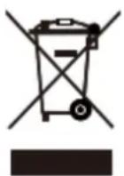
This marking indicates that this product should not be disposed with other household wastes throughout the EU. To prevent possible harm to the environment or human health from uncontrolled waste disposal, recycle it responsibly to promote the sustainable reuse of material resources. To return your used device, please use the return and collection systems or contact the retailer where the product was purchased. They can take this product for environmental safe recycling.
R32: 675
DEUTSCH
Inhalt
EIN PAAR WORTE ZU IHRER NEUEN KLIMAANLAGE 56
Roof Top Air Conditioner
VERPACKUNGSLISTE
| owner's manual | Mounting plate | remote controller | battery (AAA 1.5V) |
| Double-sided gummed paper | Remote controller holder | Sunk screw (remote controller holder) | foam(under) |
| Foam (accessory) | Sponge (foam accessory) | Mounting plate sub-assy | Bolt sub-assy M8X135 |
| Sponge (sealing strip) | Sponge | Insulating sheath | Bundle |
| Bolt sub-assy M6X25 | Tapping screw |
Indoor Unit
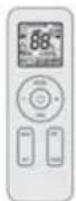
remote controller
(Display content or position may be different from above graphics, please refer to actual products)
Outdoor Unit
NOTICE:
Actual product may be different from above graphics, please refer to actual products.
Buttons on remote controller
Introduction for icons on display screen
| FA 0 | Set fan speed | |
| Send signal | ||
| Operation mode | △ | Auto mode |
| ※ | Cool mode | |
| ◇ | Dry mode | |
| ◇ | Fan mode | |
| Heat mode | ||
| Sleep mode | ||
| Light | ||
| X-FAN function | ||
| Indoor ambient temp. | ||
| Clock | ||
| 88° | Set temperature | |
| WiFi | WiFi function | |
| 88:88 | Set time | |
| ONOFF | TIMER ON / TIMER OFF | |
| Up & down swing | ||
| Child lock | ||
Note: Try you best to put the unit on the horizontal surface for operation. The unit can only operate for a short time at the maximum sloping angle of 5^ for preventing water leakage.
Above Level 5^ Max Below Level 0^ Max
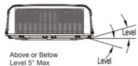
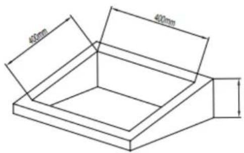
Figure 2
Height Varies to Make Unit Level
Figure 3
Roof Top Air Conditioner
LISTED D'EMBALLAGE
| owner's manual | Mounting plate | remote controller | battery (AAA 1.5V) |
| Double-sided gummed paper | Remote controller holder | Sunk screw (remote controller holder) | foam(under) |
| Foam (accessory) | Sponge (foam accessory) | Mounting plate sub-assy | Bolt sub-assy M8X135 |
| Sponge (sealing strip) | Sponge | Insulating sheath | Bundle |
| Bolt sub-assy M6X25 | Tapping screw |
Indoor Unit
remote controller
(Display content or position may be different from above graphics, please refer to actual products)
Outdoor Unit
NOTICE:
Actual product may be different from above graphics, please refer to actual products.
Buttons on remote controller
Introduction for icons on display screen
| FA 0 | Set fan speed | |
| Send signal | ||
| Operation mode | △ | Auto mode |
| ※ | Cool mode | |
| ◇ | Dry mode | |
| ◇ | Fan mode | |
| Heat mode | ||
| Sleep mode | ||
| Light | ||
| X-FAN function | ||
| Indoor ambient temp. | ||
| Clock | ||
| 88° | Set temperature | |
| WiFi | WiFi function | |
| 88:88 | Set time | |
| ONOFF | TIMER ON / TIMER OFF | |
| Up & down swing | ||
| Child lock | ||
Note: Try you best to put the unit on the horizontal surface for operation. The unit can only operate for a short time at the maximum sloping angle of 5^ for preventing water leakage.
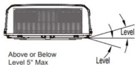

Figure 3
Roof Top Air Conditioner
LISTA DE EMBALAJES
| owner's manual | Mounting plate | remote controller | battery (AAA 1.5V) |
| Double-sided gummed paper | Remote controller holder | Sunk screw (remote controller holder) | foam(under) |
| Foam (accessory) | Sponge (foam accessory) | Mounting plate sub-assy | Bolt sub-assy M8X135 |
| Sponge (sealing strip) | Sponge | Insulating sheath | Bundle |
| Bolt sub-assy M6X25 | Tapping screw |
Indoor Unit
remote controller
(Display content or position may be different from above graphics, please refer to actual products)
Outdoor Unit
NOTICE:
Actual product may be different from above graphics, please refer to actual products.
Buttons on remote controller
Introduction for icons on display screen
| FA 0 | Set fan speed | |
| Send signal | ||
| Operation mode | △ | Auto mode |
| ※ | Cool mode | |
| ◇ | Dry mode | |
| ◇ | Fan mode | |
| Heat mode | ||
| Sleep mode | ||
| Light | ||
| X-FAN function | ||
| Indoor ambient temp. | ||
| Clock | ||
| 88° | Set temperature | |
| WiFi | WiFi function | |
| 88:88 | Set time | |
| ONOFF | TIMER ON / TIMER OFF | |
| Up & down swing | ||
| Child lock | ||
Note: Try you best to put the unit on the horizontal surface for operation. The unit can only operate for a short time at the maximum sloping angle of 5^ for preventing water leakage.
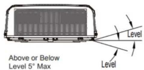
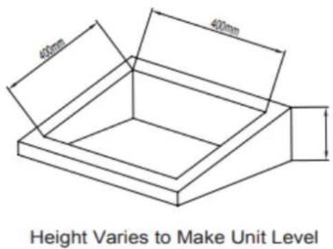
Figure 3
Roof Top Air Conditioner
ELENCO IMBALLAGGI
| owner's manual | Mounting plate | remote controller | battery (AAA 1.5V) |
| Double-sided gummed paper | Remote controller holder | Sunk screw (remote controller holder) | foam(under) |
| Foam (accessory) | Sponge (foam accessory) | Mounting plate sub-assy | Bolt sub-assy M8X135 |
| Sponge (sealing strip) | Sponge | Insulating sheath | Bundle |
| Bolt sub-assy M6X25 | Tapping screw |
Indoor Unit
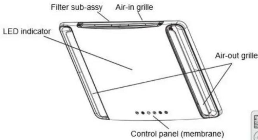
remote controller
(Display content or position may be different from above graphics, please refer to actual products)
Outdoor Unit
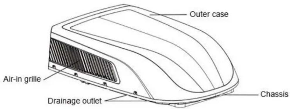
NOTICE:
Actual product may be different from above graphics, please refer to actual products.
Buttons on remote controller
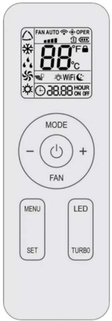
Introduction for icons on display screen
| FA 0 | Set fan speed | |
| Send signal | ||
| Operation mode | △ | Auto mode |
| ※ | Cool mode | |
| ◇ | Dry mode | |
| ◇ | Fan mode | |
| Heat mode | ||
| Sleep mode | ||
| Light | ||
| X-FAN function | ||
| Indoor ambient temp. | ||
| Clock | ||
| 88° | Set temperature | |
| WiFi | WiFi function | |
| 88:88 | Set time | |
| ONOFF | TIMER ON / TIMER OFF | |
| Up & down swing | ||
| Child lock | ||
Note: Try you best to put the unit on the horizontal surface for operation. The unit can only operate for a short time at the maximum sloping angle of 5^ for preventing water leakage.
FASE 5-CABLAGGIO ELETTRICO
INSTRADAMENTO DEL CABLAGGIO 220-240V AC
ATTENZIONE
ET PAR ORD OM DIT NYE KLIMAANLæG
Tak, fordu valgte Recreational Vehicle Air Conditioner.
Roof Top Air Conditioner
PAKKELISTE
| owner's manual | Mounting plate | remote controller | battery (AAA 1.5V) |
| Double-sided gummed paper | Remote controller holder | Sunk screw (remote controller holder) | foam(under) |
| Foam (accessory) | Sponge (foam accessory) | Mounting plate sub-assy | Bolt sub-assy M8X135 |
| Sponge (sealing strip) | Sponge | Insulating sheath | Bundle |
| Bolt sub-assy M6X25 | Tapping screw |
Indoor Unit
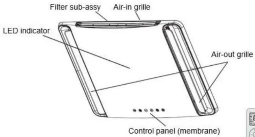
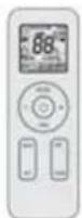
remote controller
(Display content or position may be different from above graphics, please refer to actual products)
Outdoor Unit
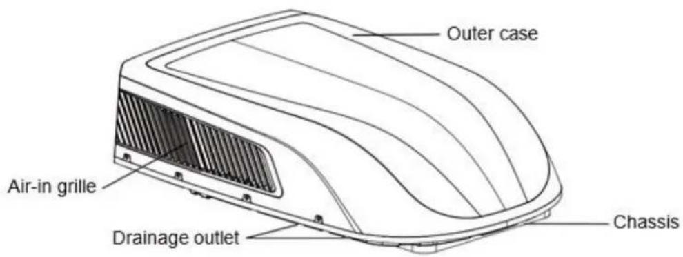
NOTICE:
Actual product may be different from above graphics, please refer to actual products.
Buttons on remote controller
Introduction for icons on display screen
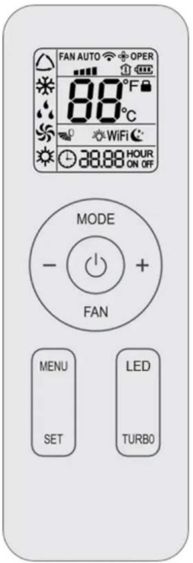
| FA 0 | Set fan speed | |
| Send signal | ||
| Operation mode | △ | Auto mode |
| ※ | Cool mode | |
| ◇ | Dry mode | |
| ◇ | Fan mode | |
| Heat mode | ||
| Sleep mode | ||
| Light | ||
| X-FAN function | ||
| Indoor ambient temp. | ||
| Clock | ||
| 88° | Set temperature | |
| WiFi | WiFi function | |
| 88:88 | Set time | |
| ONOFF | TIMER ON / TIMER OFF | |
| Up & down swing | ||
| Child lock | ||
Figure 1-2
Note: Try you best to put the unit on the horizontal surface for operation. The unit can only operate for a short time at the maximum sloping angle of 5^ for preventing water leakage.
FORSIGTIG
Above Level 5^ Max Below Level 0^ Max
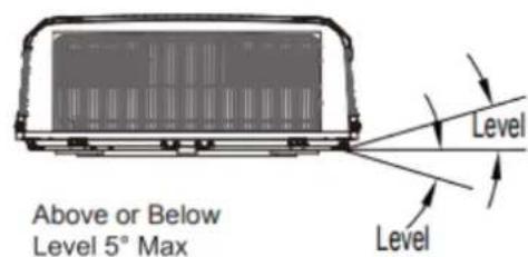
Figure 2
Figure 3
Height Varies to Make Unit Level
Bemerk: Klimaanlaeggets dimensioner (enhedens tag)
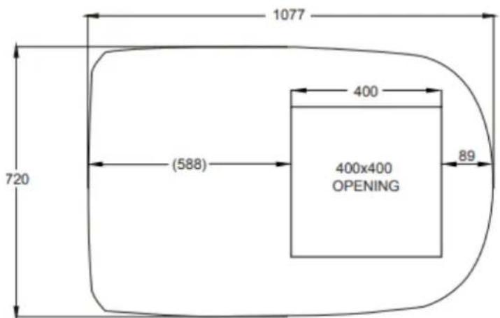
Figure 4
TRIN 3 - MONTERING AF UENDORSENHED
Figure 4-1
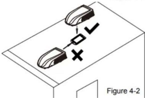
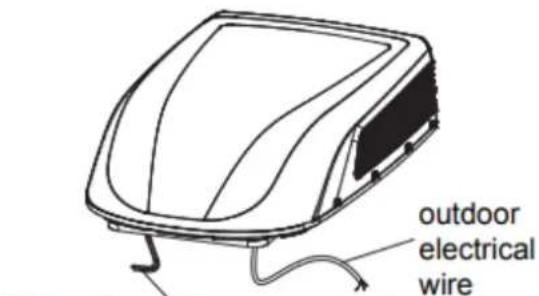
Figure 6 outdoor connect wire
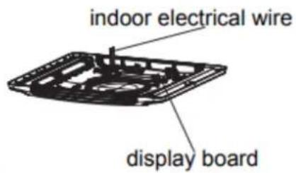
Figure 7
Roof Top Air Conditioner
FÖRPACKINGLISTA
| owner's manual | Mounting plate | remote controller | battery (AAA 1.5V) |
| Double-sided gummed paper | Remote controller holder | Sunk screw (remote controller holder) | foam(under) |
| Foam (accessory) | Sponge (foam accessory) | Mounting plate sub-assy | Bolt sub-assy M8X135 |
| Sponge (sealing strip) | Sponge | Insulating sheath | Bundle |
| Bolt sub-assy M6X25 | Tapping screw |
Indoor Unit
remote controller
(Display content or position may be different from above graphics, please refer to actual products)
Outdoor Unit
NOTICE:
Actual product may be different from above graphics, please refer to actual products.
Buttons on remote controller
Introduction for icons on display screen
| FA 0 | Set fan speed | |
| Send signal | ||
| Operation mode | △ | Auto mode |
| ※ | Cool mode | |
| ◇ | Dry mode | |
| ◇ | Fan mode | |
| Heat mode | ||
| Sleep mode | ||
| Light | ||
| X-FAN function | ||
| Indoor ambient temp. | ||
| Clock | ||
| 88° | Set temperature | |
| WiFi | WiFi function | |
| 88:88 | Set time | |
| ONOFF | TIMER ON / TIMER OFF | |
| Up & down swing | ||
| Child lock | ||
Valj driftlage, COOL, FAN, HEAT
- FILTER CHECK indicator
Note: Try you best to put the unit on the horizontal surface for operation. The unit can only operate for a short time at the maximum sloping angle of 5^ for preventing water leakage.
Above Level 5^ Max Below Level 0^ Max
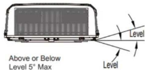
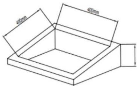
Figure 2
Height Varies to Make Unit Level
Figure 3
Obs: Luftkonditioneringens matt (aggregatets tak)
Figure 4
STEG 3 - MONTERING AV UTOMHUSENHET
Figure 4-1
NOEN ORD OM DET NYE KLIMAANLEGGET DITT 207
ELEKTRISKE DATA 208
ELEKTRISK DIAGRAM 209
PAKKELISTE 210
PARTS NAME 211
BETJENING AV TRÄDLØS FJERNKONTROLL 212
KONTROLLPANEL 216
INSTALLASJONSINSTRUKSJONER 217
TRNN 1 - FEST SVAMPEN (TETNINGSLISTEN) OG SVAMPEN PÅ UTENDØRSENHETEN......217
TRINN 2 - VALG AV INSTALLASJONSSTED OG MONTERING AV KLIMAANLEGGET PÅ TAKET 217
TRINN 3-MONTERING AV UTENDØRSENHET 220
TRINN 4-MONTERING AV TAKMONTERINGEN 220
TRINN 5 - ELEKTRISK KABLING 221
TRINN6-FULLFOREINSTALLASJONEN 222
FEILSKINGSVEILEDNING 223
FEILKODE 224
NORMALEVEDLIKEHOLDSPROSEDYRER 224
SPESIALISTHANDBOK 224
NOEN ORD OM DET NYE KLIMAANLEGGET DITT
Takk for at du valgte klimaanlegget for fritidskjorety.
Roof Top Air Conditioner
PAKKELISTE
| owner's manual | Mounting plate | remote controller | battery (AAA 1.5V) |
| Double-sided gummed paper | Remote controller holder | Sunk screw (remote controller holder) | foam(under) |
| Foam (accessory) | Sponge (foam accessory) | Mounting plate sub-assy | Bolt sub-assy M8X135 |
| Sponge (sealing strip) | Sponge | Insulating sheath | Bundle |
| Bolt sub-assy M6X25 | Tapping screw |
Indoor Unit

remote controller
(Display content or position may be different from above graphics, please refer to actual products)
Outdoor Unit
NOTICE:
Actual product may be different from above graphics, please refer to actual products.
Buttons on remote controller
Introduction for icons on display screen
| FA 0 | Set fan speed | |
| Send signal | ||
| Operation mode | △ | Auto mode |
| ※ | Cool mode | |
| ◇ | Dry mode | |
| ◇ | Fan mode | |
| Heat mode | ||
| Sleep mode | ||
| Light | ||
| X-FAN function | ||
| Indoor ambient temp. | ||
| Clock | ||
| 88° | Set temperature | |
| WiFi | WiFi function | |
| 88:88 | Set time | |
| ONOFF | TIMER ON / TIMER OFF | |
| Up & down swing | ||
| Child lock | ||
Note: Try you best to put the unit on the horizontal surface for operation. The unit can only operate for a short time at the maximum sloping angle of 5^ for preventing water leakage.
Above Level 5^ Max Below Level 0^ Max
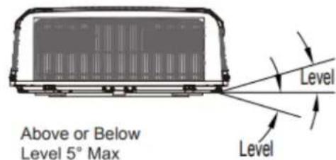
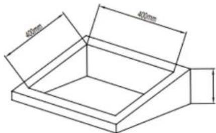
Figure 2
Height Varies to Make Unit Level
Figure 3
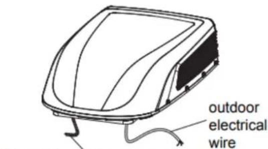
Figure 6 outdoor connect wire
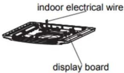
Figure 7
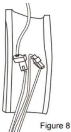
Figure 8
-
Bruk beskyttelseshylse til a pakke inn ledningsterminalen, fest beskyttelseshylsen og bruk deretter kabelbinder for a pakke dem tettSAM men Merk:
-
Kabelen mä festes i begge ender av ledningsterminalen.
- Fd du monterer frontpanelet pa innendorsenheten, ma du legge den varmeisolerende kappen pa toppen av luftkanalen.
TRINN 6-FULLFØRE INSTALLASIONEN
NORMALE VEDLIKEHOLDSPROSEDYRER