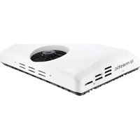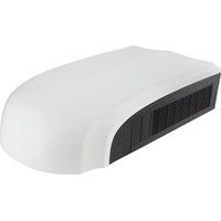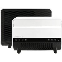
SPA-3100 - Air Conditioning Mestic - Free user manual and instructions
Find the device manual for free SPA-3100 Mestic in PDF.


User questions about SPA-3100 Mestic
0 question about this device. Answer the ones you know or ask your own.
Ask a new question about this device
Download the instructions for your Air Conditioning in PDF format for free! Find your manual SPA-3100 - Mestic and take your electronic device back in hand. On this page are published all the documents necessary for the use of your device. SPA-3100 by Mestic.
USER MANUAL SPA-3100 Mestic
text_image
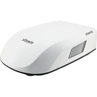
Vehicles up to 5 m 3200 BTU (938 W) 53 dB Mode 3 speeds KG 19 kg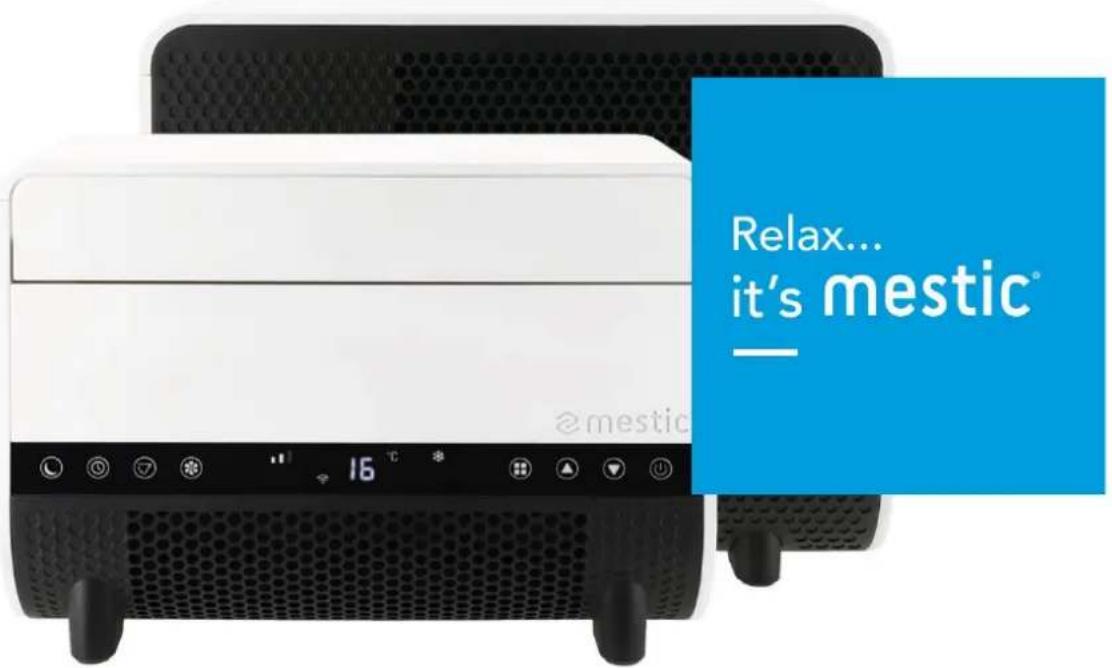
text_image
Relax... it's mestic® @mesticSPLIT UNIT AIR CONDITIONER SPA-3100
text_image
Stepping Motor MOTO MAIN BOARD ACN FAN ACL COMP. CN2 WATER2 PT RT Coil sensor Room sensor LED DISPLAY DSP Water Level Sensor Blue Red White Water pump ~220V-240V50Hz Brown Blue GN/YW L N E White Yellow Black Red Blue Fan Motor Terminal Board L C N Blue Red Brown White Fan Motor GN/YW Blue Red C Black S COMP. C R Blue GN/YW4. Paklijst
text_image
Exploded view diagram of a smart air conditioner unit with numbered parts for identification5. Onderdelen
Totaal
text_image
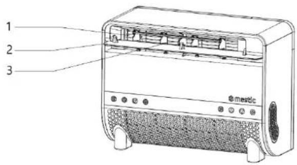
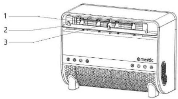
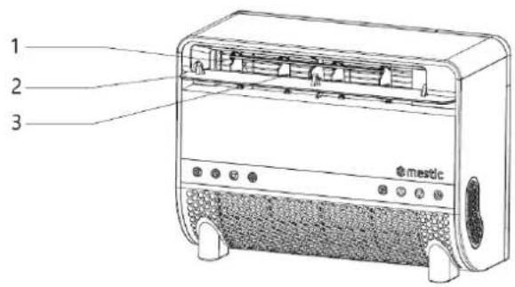
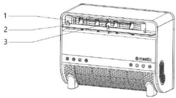
1 2 3 mastic- Luchtuitlaat
- Klep
natural_image
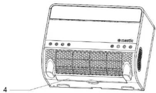
Line drawing of a portable air purifier with labeled components and panel slots (no text or symbols beyond labels)- Netafdekking
- Filter
Machine
text_image
5 6 7 8 9 10 11- @matictext_image
Technical diagram of a device with numbered parts labeled 12 to 21, showing internal components and connections.text_image
Technical diagram of a mechanical device with labeled parts 5 and 6, showing components like a vertical support and mounting bracket.natural_image
Technical line drawing of a mechanical bracket assembly before and after modification (no text or symbols)natural_image
Technical line drawing of a mechanical device with an inset view showing its internal components (no text or symbols)natural_image
Simple line drawing of an oval shape with a rectangular panel and four small circular objects inside (no text or symbols)7. Bedieningshandleiding
- Inschakelen
text_image
Diagram showing three stages of an electric heater with labeled components and airflow direction arrowsnatural_image
Line drawing of two electric blower units connected by a screwdriver, showing front and side views (no text or symbols)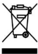
1. Safety Instructions
Warning
When using this air conditioner, it is important to always adhere to the safety instructions. This helps to prevent personal injury, electric shock, and product damage. Be sure to read all instructions beforehand.
- Read the manual before use.
- The manufacturer is not liable for damage or injury resulting from use if the operating conditions are not met.
- Keep the manual, warranty certificate, and receipt.
- Supervise children to ensure they do not play with the device.
- This appliance is not intended for use by children under 8 years old or persons with physical, sensory, or mental impairments, or insufficient experience and knowledge, unless they are supervised or instructed by a responsible person.
- Never use the appliance if it is visibly damaged or if there are breaks in the cord.
- Do not attempt repairs on a damaged appliance, cord, or plug yourself. Always have this done by the manufacturer or a qualified technician.
- The appliance is not suitable for commercial use.
• Always use and store the appliance in a dry place.
- Never use accessories that are not recommended by the manufacturer.
• This appliance is only intended for household use and its designated purpose.
- Modifying this product (or parts of it) is prohibited.
- Never connect multiple electrical devices to one outlet to avoid poor connection and excessive heat load.
- It is forbidden to place the portable air conditioner (both indoor and outdoor units) in rain or water.
Warnings
- Keep a minimum distance of 2 meters from burning objects to comply with fire prevention measures.
- Minimum storage and usage space (recommended >4m^2 ).
- Users are strictly prohibited from refilling refrigerant themselves.
- Do not pull or damage the hose with sharp objects. If the hose appears damaged, stop using the device and contact the distributor for repairs.
Air Conditioner Installation Location
The air conditioner must be placed on a sturdy, flat surface (note: the air conditioner must not be tilted or uneven) during use. This portable air conditioner must not be installed in the following locations:
- Near strong heat sources, fumes, flammable, or explosive gases.
- In an environment containing chemicals (evaporative substances, organic solvents, etc.).
- In wet conditions. If it rains, the air conditioner must be removed from the window.
- For outdoor use, keep the air conditioner away from rain and/or water.
Additional Provisions
- The product must always and under all circumstances remain upright. It is forbidden to hold the appliance sideways or upside down.
- When moving or carrying the air conditioner, keep it upright. Ensure it is not shaken or dropped.
• Make sure the air intake is not blocked and remains well-ventilated. - Do not insert objects into the air inlet or outlet openings, as they may come into contact with electrical components or the fan, posing a danger.
- Do not place heavy objects on the product.
- Unplug the device before moving, maintaining, cleaning, or storing it for a long period.
- Do not pull the plug to move the machine.
- Clean the dust screen of the air intake at least once a month.
- If the machine will not be used for an extended period, store it in a cool, dry place. Clean and dry the air conditioner beforehand.
Maintenance Safety Instructions
Follow these warnings when maintaining a device with R290 refrigerant:
-
Environment Check: Before working on systems with flammable refrigerants, safety checks must be performed to minimize the risk of ignition. Inspect the working environment for potential hazards.
-
Work Procedure: Perform tasks under controlled conditions to minimize the presence of flammable gases or vapors.
-
General Workspace: Inform all maintenance personnel and others nearby about the nature of the work. Avoid working in enclosed spaces and isolate the work area. Remove flammable materials from the environment to ensure safety.
-
Refrigerant Detection: Use a suitable refrigerant detector to check the environment before and during work to detect possible flammable atmospheres. Ensure the detection equipment is spark-free, well-sealed, or intrinsically safe.
-
Fire Extinguisher: If hot work is required on the cooling system or parts of it, appropriate firefighting equipment must be available. This includes a dry powder or CO2 extinguisher suitable for flammable refrigerants and within immediate reach for emergencies.
-
No Ignition Sources: Workers handling a cooling system containing flammable refrigerants should not use ignition sources. Keep all potential ignition sources, including smoking, away from installation, repair, disposal, and waste processes. Display "No Smoking" signs.
-
Ventilated Area: Ensure the workspace is outdoors or well-ventilated before opening the system or performing hot work. Ventilation must continue during work to safely disperse released refrigerant.
-
System Inspection: Replaced electrical components must be suitable and meet the correct specifications. Always follow the manufacturer's maintenance and service instructions. Consult the manufacturer's technical department if in doubt.
o Verify that the refrigerant charge matches the room size where the parts are installed.
- Ensure ventilation machines and outlets are functioning properly and not blocked.
- Check the secondary circuit for refrigerant presence if an indirect cooling system is used.
o Ensure markings on the equipment remain visible and legible. Replace unreadable markings.
○ Check that cooling pipes or components are not exposed to substances causing corrosion unless they are corrosion-resistant or well-protected.
- Electrical Device Inspection: Repair and maintenance of electrical components must start with safety checks and inspection procedures. If a malfunction compromises safety, do not connect electrical power to the circuit until the issue is resolved.
○ Discharge capacitors safely to prevent sparks.
- Ensure there are no exposed electrical components or wiring during system charging, recovery, or flushing.
o Verify the grounding connection is intact.
2. Technical specifications
| Voltage | 220~240V AC 50 Hz | Airflow Capacity | 180-250 m3/h |
| Cooling Capacity | 3200 BTU (938W) | Dehumidification Capacity | 0,2 kg/h |
| Power | 387W | Insulation Class | IPX4 |
| Refrigerant | R290 (112g) | Compressor Type | Rotor type |
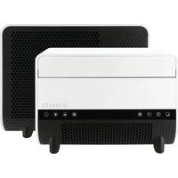
| Indoor Unit Dimensions | 43.2 X 32 X 19.8cm | Noise Level | 53 dB |
| Outdoor Unit Dimensions | 45.5 X 37.4 X 20.9cm | Weight | 19 kg |
- Electrical Diagram
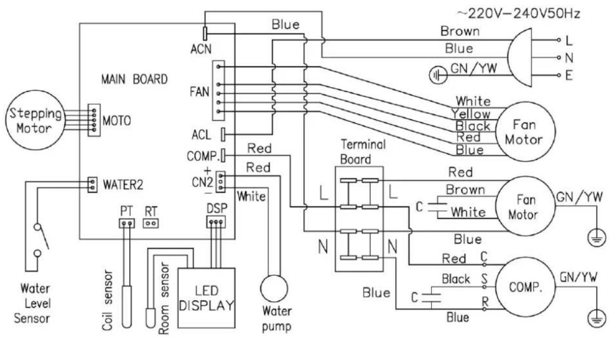
flowchart
graph TD
    A["Stepping Motor"] --> B["MOTO"]
    B --> C["MAIN BOARD"]
    C --> D["ACN"]
    C --> E["FAN"]
    C --> F["ACL"]
    C --> G["COMP."]
    C --> H["CN2"]
    C --> I["Water2"]
    I --> J["PT"]
    I --> K["RT"]
    I --> L["Coil sensor"]
    I --> M["Room sensor"]
    M --> N["LED DISPLAY"]
    N --> O["SP"]
    O --> P["White"]
    P --> Q["Terminal Board"]
    Q --> R["L"]
    Q --> S["N"]
    Q --> T["Blue"]
    Q --> U["Red"]
    Q --> V["Brown"]
    Q --> W["Black"]
    Q --> X["Blue"]
    Q --> Y["Red"]
    Q --> Z["Brown"]
    Q --> AA["White"]
    Q --> AB["Blue"]
    Q --> AC["Red"]
    Q --> AD["Black"]
    Q --> AE["S"]
    Q --> AF["COMP."]
    AF --> AG["GN/YW"]
    AH["~220V-240V50Hz"] --> AI["Brown"]
    AH --> AJ["Blue"]
    AH --> AK["GN/YW"]
    AH --> AL["L"]
    AH --> AM["N"]
    AH --> AN["E"]
4. Packing list
| Nr. | Name | Amount |
| 1 | Indoor Unit | 1 |
| 2 | Outdoor Unit | 1 |
| 3 | Upper Bracket | 2 |
| 4 | Lower Bracket Mount | 2 |
| 5 | Storage bracket | 2 |
| 6 | User Manual | 1 |
| 7 | Shockproof Rubber Support Pad | 2 |
| 8 | Hand Screws (M6x10) with Twist Knob | 14 |
| 9 | Support Block | 2 |
| 10 | Drain hose | 1 |
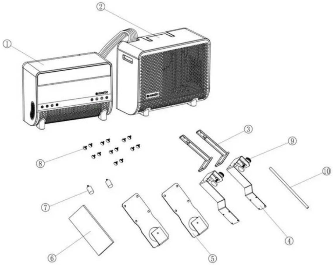
text_image
Exploded view diagram of an air conditioner unit with numbered parts for identification5. Parts
Total
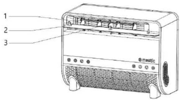
text_image
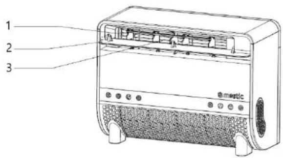
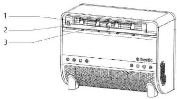
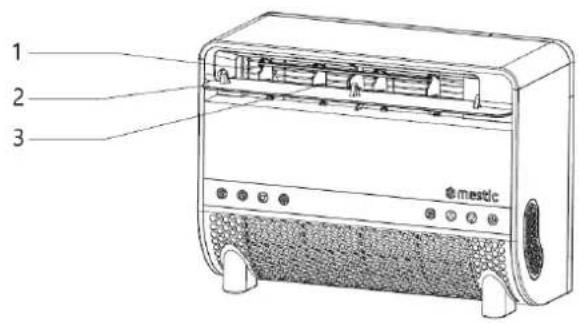
1 2 3 mestic- Air outlet
- Baffle
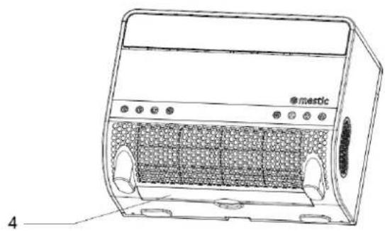
natural_image
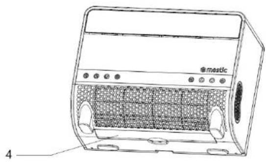
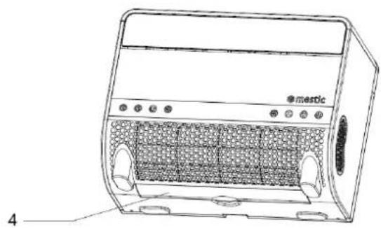
Line drawing of a portable electric heater with labeled ports and panel (no text or symbols beyond branding)- Net cover
- Filter
Machine
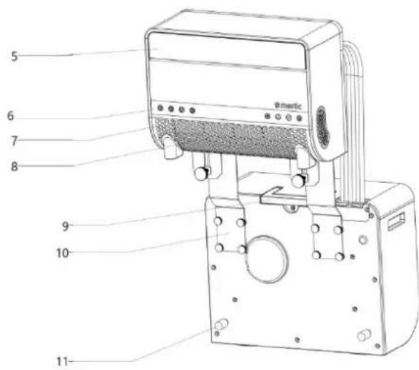
text_image
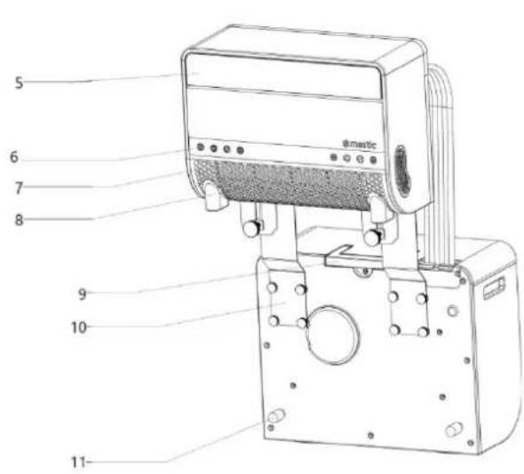
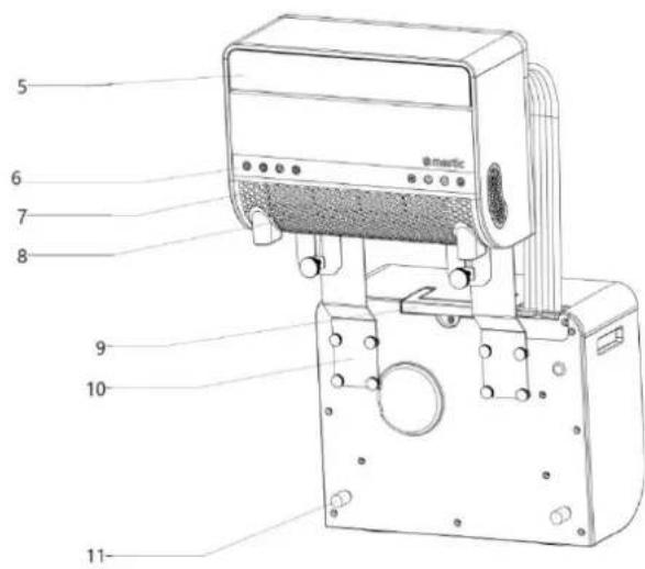
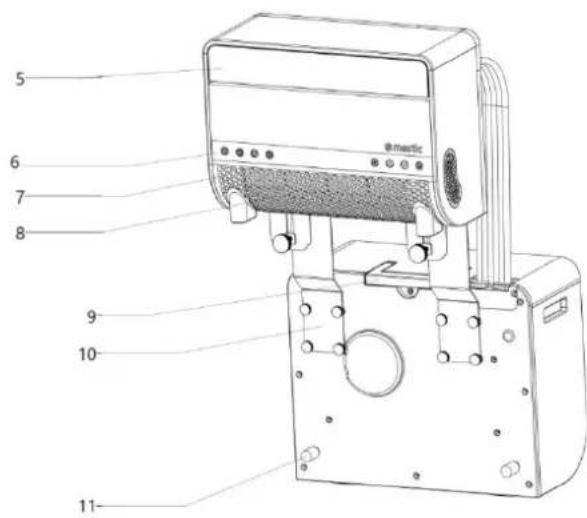
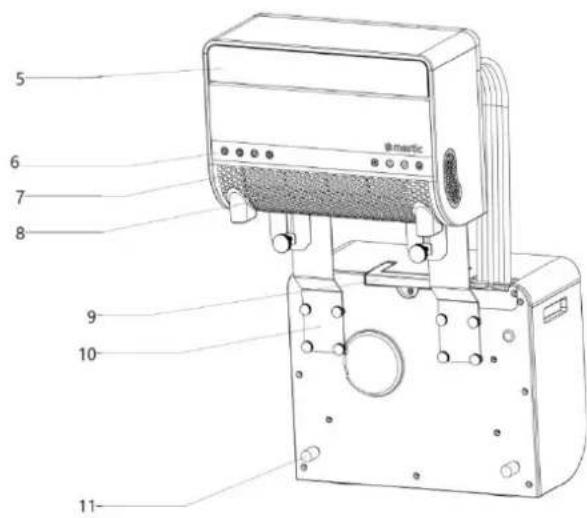
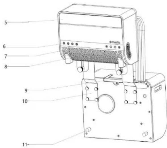
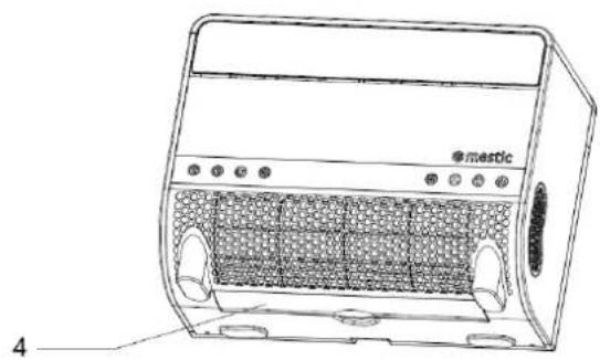
5 6 7 8 emetic 9 10 11- Baffle
- Operating button
- Air inlet board
- Air inlet
- Handle
- Down bracket
- Shockproof support rubber pad
- Back cover
- Flexible hose
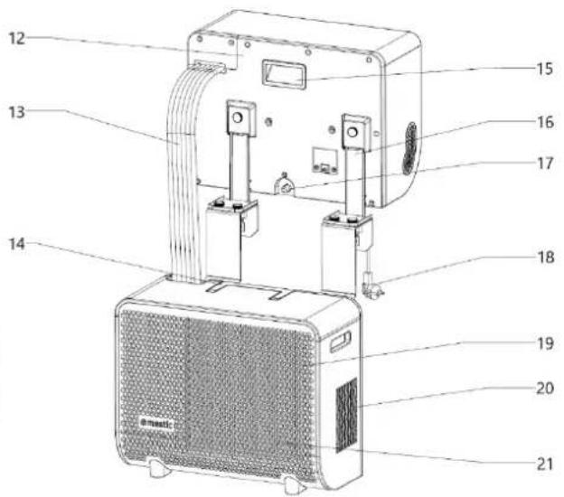
text_image
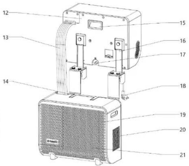
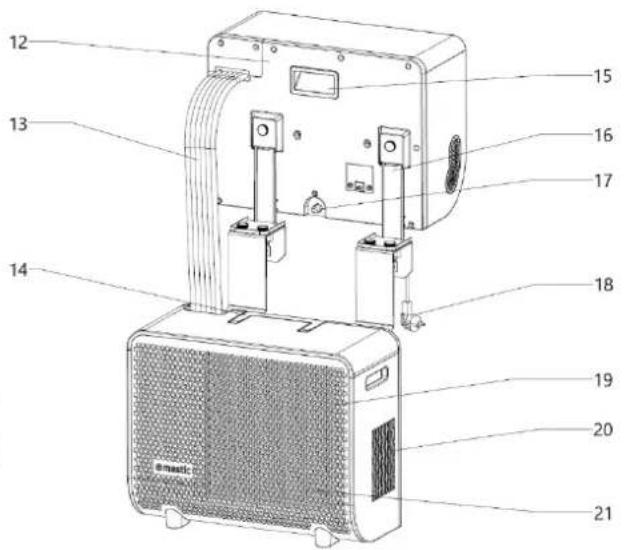
Technical diagram of a device with numbered parts labeled 12 to 21- Handle
- Handle
- Upper bracket
- Condensate drain cover
- Power cord
- Air inlet board
- Air outlet
- Air inlet
Accessories
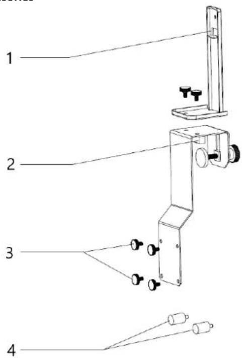
text_image
1 2 3 4- Upper Bracket
- Support Block
- Hand-Tightening Screws
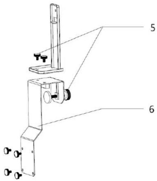
text_image
Technical diagram of a mechanical device with labeled parts 5 and 6, showing components like a vertical support and mounting bracket.- Shockproof Rubber Pad
- Hand-Tightening Lock
- Lower Bracket
Control panel
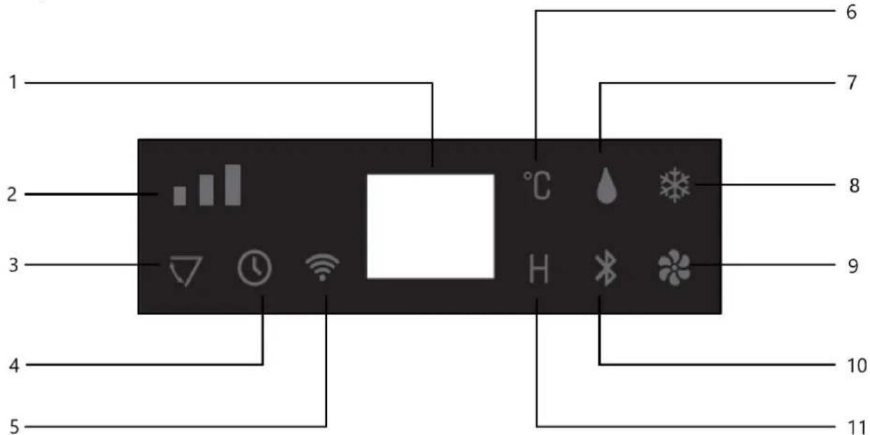
text_image
1 2 3 4 5 6 7 8 9 10 11- Digital Indicator Light
- Fan Speed Indicator Light
- Swing Blade Indicator Light
- Timer Function Indicator Light
- Wi-Fi Indicator Light
-
Celsius Degree Indicator Light
-
Dehumidification Mode Indicator Light
- Cooling Mode Indicator Light
- Fan Mode Indicator Light
- BLUETOOTH Mode Indicator Light
- Time Symbol Indicator Light
Frontpanel
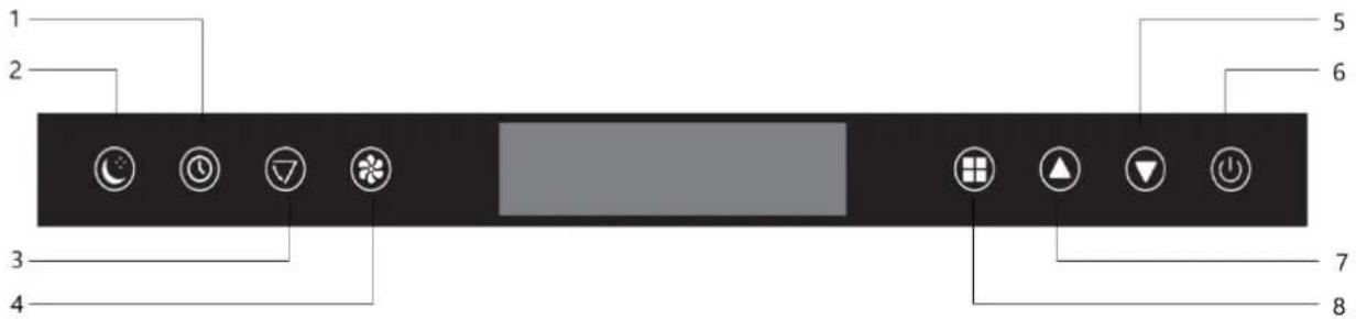
text_image
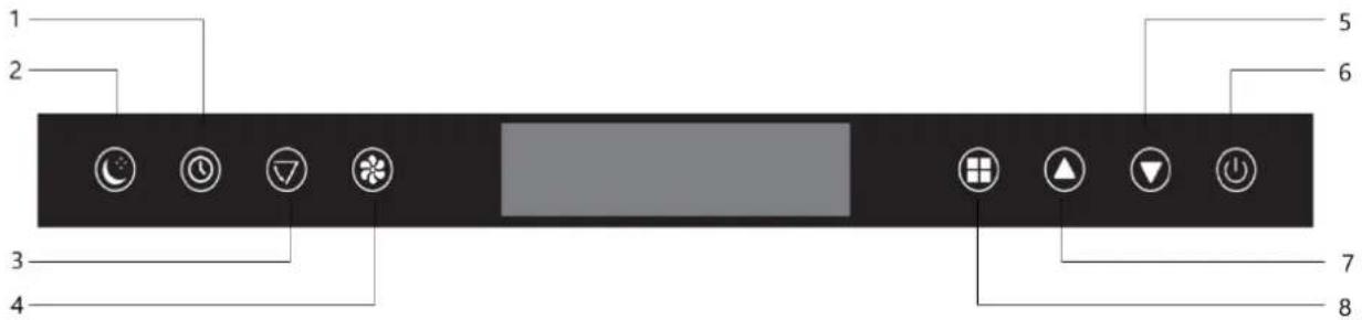
1 2 3 4 5 6 7 8-
Timer Function
-
Decrease Set Temperature
-
Sleep Mode
-
ON/OFF
-
Swing Blade Operation
-
Increase Set Temperature
-
Fan Speed
-
Operating Mode
6. Installation of the airco
- Unpack the machine and accessories, and check if the hose between the indoor and outdoor units is properly connected. Also, ensure that the condensate water drain is equipped with a rubber cover. Finally, verify that all accessories are complete.
- Install the accessories as shown in the illustration. Connect the outer bracket to the support block and the lower bracket by tightening the hand screws. This will form the carrying bracket.
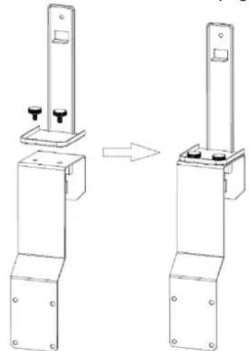
natural_image
Technical line drawing of a mechanical bracket assembly before and after transformation (no text or symbols)a. Install the bracket as shown in the image below. Mount the indoor and outdoor units onto the bracket to secure the two parts. Attach the units to the bracket by tightening the hand screws in the designated holes.
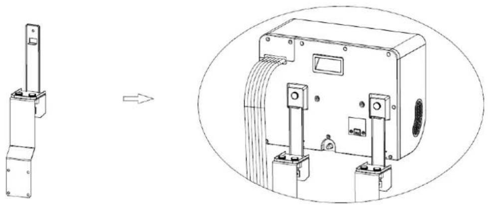
natural_image
Technical line drawing of a mechanical device with an inset showing its assembly (no text or symbols present)b. Place the shockproof rubbers on the back of the outdoor unit.
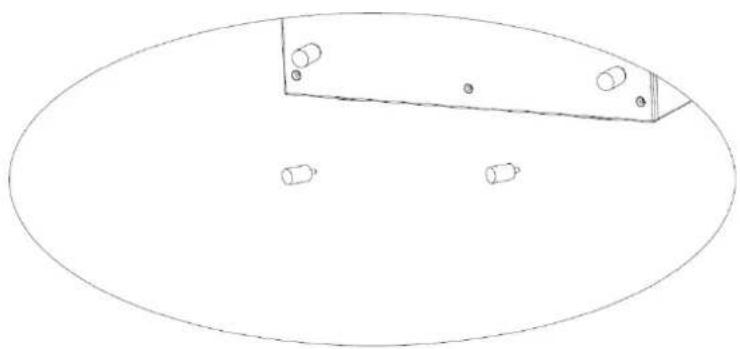
natural_image
Simple line drawing of an oval shape with a rectangular panel and four small circular features inside (no text or symbols)7. Use
- Power On
Plug the power cord into the socket. The machine will emit a short beep, and the display and indicator lights will illuminate for 3 seconds. Then the BLUETOOTH and WIFI symbols will blink, indicating that the machine is powered on.
- Turn On
Press the button on the panel of the indoor unit. The machine will turn on and emit a short beep. The digital display will light up, showing the initial set temperature "24°C". Simultaneously, the middle wind indicator light and the air conditioning light will turn on, and the indoor unit fan will start running. At this point, if the temperature sensor detects that the ambient temperature is higher than "24°C", the compressor will start, and the outdoor unit fan will begin to operate. If the temperature sensor detects that the ambient temperature is lower than "24°C", the compressor will not start, and the outdoor unit fan will not operate.
- Fan Mode
Each time you press the button, the machine may emit a short beep. The indoor unit fan will operate in the sequence "Medium Wind" - "High Wind" - "Low Wind" - "Medium Wind" - "High Wind", corresponding to the wind speed indicator light. The display will also show the corresponding speed symbol.
In dehumidification mode, the wind speed and set temperature cannot be adjusted. The wind speed operates at a low level, and the ambient temperature is displayed.
- Selecting Mode
Each time you press the button, the machine emits a short beep. The operating mode of the indoor unit cycles between "Dehumidify" - "Fan" - "Cool". The corresponding symbol will appear on the display.
Dehumidify Mode: The symbol light is on, the compressor and outdoor unit fan are operating, and the fan will run. The wind speed and set temperature cannot be adjusted. The wind operates at a low level, and the ambient temperature is displayed.
Fan Mode: The symbol light is on, but the compressor and outdoor unit fan are not operating; only the fan will run.
Cool Mode: The symbol light is on, and the compressor, outdoor unit fan, and indoor fan are all operating.
• Temperature Setting
Each time you press the button, the machine emits a short beep, and the set temperature increases by "1°C". The maximum adjustable temperature is "31°C".
Each time you press the button, the machine emits a short beep, and the set temperature decreases by "1°C". The minimum adjustable temperature is "16°C".
- Sleep Mode Activation
Press the button. The machine emits a short beep. All indicator lights and the digital display turn off after 3 seconds, and the machine enters sleep mode. The indoor fan operates at a low wind speed. Press any button on the control panel, and the machine emits a short beep, returning to its original operating state.
- Turn Off
When the machine is on, press the ⏻ button. The machine emits a long beep ("beep—"), all indicator lights turn off, the machine stops working, and it enters standby mode. The machine remains ready to be turned on again.
- Wi-Fi function
☐ In the OFF state (with the power on), long press the "wind speed" button for 3 seconds to reset the Wi-Fi connection, and the Wi-Fi will enter the connectable state.
When the Wi-Fi is connecting, the Wi-Fi indicator flashes quickly. When the Wi-Fi connection is successful, and the Wi-Fi indicator is steady on
- Bluetooth function
○ Long press the "Mode" button in the shutdown state for 3 seconds to reset the Bluetooth connection, and the Bluetooth will enter the connectable state.
The Bluetooth connection is successful, and the Bluetooth indicator is steady on. Other status The Bluetooth indicator is flashing.
- Timer
Press the button. When the timer indicator light turns on, the display will show "00H". Each press increases the set time by "1H", up to a maximum of "24H". Each press of the button decreases the set time by "1H", to a minimum of "00H".
- Ventilatieblad
Press the button. When the indicator light turns on, the swing blade begins to move. Press the button again to stop the blade from moving.
8. Connecting the device to the Mestic app
- Installing the app
- Download the free Mestic app from the Apple App Store or the Google Play Store.
- Create an account or log in. Enter a valid email address to receive the verification code.
- Connect the device to the app
- Plug the air conditioner into the power outlet. Make sure you have Wi-Fi connection and Bluetooth enabled on your smartphone. The air conditioner is in standby mode, all touch buttons light up.
- Open the app, log in and press the '+' button on the top right and select 'Add Device'.
- Select "major home appliances", select "air conditioner (Bluetooth+Wi-Fi)" and accept location services if necessary.
- Check if the Wi-Fi light on the device flashes fast (3x per second). If the light blinks slowly, press and hold the fan button for 3 seconds until you hear a "beep" to exit Wi-Fi mode. Press the fan button again for 3 seconds until you hear a 'beep' to restart Wi-Fi mode.
- In the app, confirm that the light is blinking rapidly.
- Select the Wi-Fi network (*) you are connected to and enter your Wi-Fi password.
- Click 'next' to pair the air conditioner with the app.
- App features
- Power button: You can use the power button to turn the device on or off no matter where you are.
- Temperature settings: You can set the temperature from 16^ C to 31^ C.
- Current temperature: You can check the current ambient temperature.
- Operating mode: You can change the mode to cooling, dehumidifying or ventilating.
- Fan speed: You can change the fan speed to low, medium or high.
- Function: You can set the ventilation to running and/or you can set sleep mode here.
- Timer: Here you can set a timer for turning on and off and also select the desired mode, fan speed and temperature settings.
9. Error Code list
| Error codes | ||
| Error code | Cause | Solution |
| E1 | Room temperature sensor fault | Contact the dealer |
| E2 | System temperature sensor fault | |
| E4 | Insufficient refrigerant | |
| E6 | Condensation pump malfunction | |
| EC | Loose wires or damaged components on the circuit board. | |
| Problem | Cause | Solution |
| The device does not turn on | No power | Turn power on |
| Damaged electrical outlet | Turn off the power and check / repair the power outlet | |
| Unknown reason | Contact the dealer | |
| Little air displacement or limited cooling effect | The lowest ventilation setting is selected | Select the medium or high ventilation speed modus |
| The air filter is dirty | Check and clean the filter | |
| The air supply or exhaust of the indoor unit is blocked | Check that the unit is not blocked and remove the obstruction | |
| The air supply or exhaust from the outdoor unit is blocked | Check that the unit is not blocked and remove the obstruction | |
| The ambient temperature is too low or high | The ambient temperature must be between 16 and 40 °C | |
| Insufficient voltage from the power supply | Consult an installer or use a different power connection | |
| Air displacement only but no cooling effect | The device runs in ventilation mode | Select the cooling mode (A / C) |
| The cooling mode has just turned off automatically | Wait about 3-5 minutes until the thermostat switches on again | |
| Abnormal sounds or vibrations | The mounting brackets are not properly installed on the vehicle, or the device mounting screws are not sufficiently tightened | Check that the mounting bracket is tight and tighten the device mounting screws |
| Water is leaking from the indoor unit | The rubber stopper on the bottom of the indoor unit is missing, or is not pressed enough | Check or replace the plug |
| The device is at an angle | The device must be mounted horizontally (maximum angle <3 °) | |
| The appliance emits a related odor | There is a serious problem | Switch off the device immediately and contact the dealer |
10. Maintenance
• Cleaning During the Usage Season
• Always unplug the machine before cleaning it.
- Clean the exterior: Use a damp cloth first, then wipe it with a dry cloth. Do not allow water or cleaning agents to enter the machine. Do not clean the machine with gasoline or paint thinner.
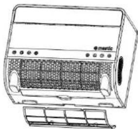
- Clean the filter mesh: If there is a lot of dust on the air filter mesh, it must be cleaned. Remove the filter as shown in the illustration below and rinse it with tap water or use a vacuum cleaner to remove the dirt. Allow the filter to dry and then place it back in the machine. Do not use water hotter than 40^ C, and avoid exposing the filter to direct sunlight.
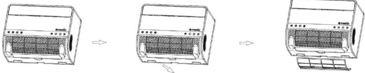
text_image
Diagram showing three stages of an e-metric air conditioner unit with labeled components and airflow direction arrowsMaintenance After the Usage Season:
- Remove the condensate drain cover from the machine, let the condensate water drain in an appropriate place, and replace the cover.
• Follow the same procedure as in "Cleaning During the Usage Season" to clean the machine again.
- Clean the filter nets of the left and right side panels: When the air filter net of the left and right side panels contains more dust, it should be cleaned. Unscrew the screw with a screwdriver according to the figure below, remove the filter net, and rinse it with tap water or use a vacuum cleaner to remove the grime on the filter net. Dry it before reloading it back into the machine. Do not use water hotter than 40°C for cleaning, and do not expose it to the sun.
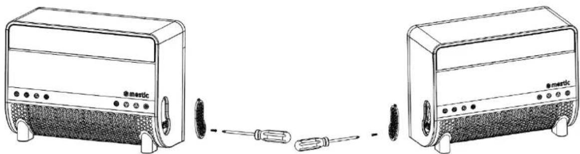
natural_image
Line drawing of two electric blower units connected by a screwdriver, showing front and side views (no text or symbols)
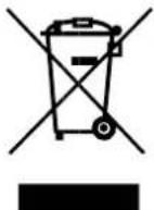
Correct disposal of this product.
This symbol means that this product should not be disposed of with normal household waste (2012/19 / EU). Recycle responsibly to promote sustainable reuse of material resources and to prevent potential damage to the environment or human health. Do you want to return the used device? Read the warranty conditions of where the product was purchased. Here you can return the product for environmentally safe recycling.
Declaration of conformity
Hereby Gimeg Nederland B.V., declares that the device SPA-3100, complies with the basic requirements and other relevant regulations listed in the European Electromagnetic Compatibility Directive (2014/30/EU) and Low Voltage Directive (2014/35/EU). A complete declaration of conformity can be requested from the address listed on the back.
text_image
Stepping Motor MOTO MAIN BOARD ACN FAN ACL COMP. CN2 WATER2 PT RT Room sensor LED DISPLAY Water Level Sensor Coil sensor Red Red White Water pump ~220V-240V50Hz Brown Blue GN/YW L N E White Yellow Black Red Blue Fan Motor Terminal Board L C N Red Brown White Fan Motor GN/YW Blue Red C C Black S R COMP. Blue GN/YW4. Packliste
text_image
Exploded view diagram of an air conditioner unit with numbered parts for identification5.Teile
Gesamt
text_image
1 2 3 mestic- Luftauslass
- Klappe
natural_image
Line drawing of a portable electric heater with labeled components and panel indicators (no text or symbols on the device itself)text_image
Technical diagram of a device with numbered parts labeled for identificationtext_image
Technical diagram of a mechanical device with labeled parts 5 and 6, showing components like a vertical support and mounting bracket.natural_image
Technical line drawing of a mechanical bracket assembly before and after modification (no text or symbols)natural_image
Technical line drawing of a mechanical device with an arrow indicating transformation (no text or symbols present)natural_image
Simple line drawing of an oval shape with a rectangular panel and four small circular features inside (no text or symbols)- Installing the app
text_image
Diagram showing three stages of a shared electric heater with labeled components and airflow direction arrowsnatural_image
Line drawings of two electric blower units connected by a screwdriver, showing front and side views (no text or symbols)
natural_image
Symbol of a trash bin crossed with two crossed lines, no text or labels present2. Technical specifications
text_image
Stepping Motor MOTO MAIN BOARD ACN FAN ACL COMP. CN2 WATER2 PT RT Coil sensor Room sensor LED DISPLAY Water Level Sensor Blue Red White Red Blue ~220V-240V50Hz Brown Blue GN/YW L N E White Yellow Black Red Blue Fan Motor Terminal Board L L C White N N Blue Red Brown Fan Motor GN/YW Blue Red C Black S COMP. GN/YW C R Bluetext_image
Exploded view diagram of an e-metric air conditioner unit with numbered parts for identification5. Pièces
Total
text_image
1 2 3 mesticnatural_image
Line drawing of a portable electric heater with labeled ports and panel (no text or symbols beyond branding)- Couverture en filet
- Filtre
Machine
text_image
5 6 7 8 9 10 11 @matictext_image
Technical diagram of a device with numbered parts labeled for identificationtext_image
Technical diagram of a mechanical device with labeled parts 5 and 6, showing components like a vertical support and mounting bracket.natural_image
Technical line drawing of a mechanical bracket assembly before and after modification (no text or symbols)natural_image
Technical line drawing of a mechanical device with an inset view showing a component assembly (no text or symbols)natural_image
Simple line drawing of an oval shape with a rectangular panel and four small circular objects on its sides (no text or symbols)7. Use
- Mise sous tension
natural_image
Line drawings of a portable air conditioner unit showing internal components and airflow direction (no text or symbols)natural_image
Line drawings of two electric blower units connected by a screwdriver, showing front and side views (no text or symbols)
1. Safety Instructions
Advertencia
2. Technical specifications
text_image
Stepping Motor MOTO MAIN BOARD ACN FAN ACL COMP. CN2 WATER2 PT RT Coil sensor Room sensor LED DISPLAY SP Blue Red White Water pump ~220V-240V50Hz Brown Blue GN/YW L N E White Yellow Black Red Blue Fan Motor Terminal Board L C N Blue Red Brown White Fan Motor GN/YW Blue Red C C Black S R COMP. GN/YWtext_image
Exploded view diagram of an e-metric air conditioner unit with numbered parts for identification5.Piezas
Total
text_image
1 2 3 mestic- Salida de aire
- Deflector

natural_image
Line drawing of a portable electric heater with labeled ports and panel (no text or symbols beyond branding)- Cubierta de malla
- Filtro
Máquina
text_image
5 6 7 8 emetic 9 10 11text_image
Technical diagram of a device with numbered parts labeled for identificationtext_image
Technical diagram of a mechanical device with labeled parts 5 and 6, showing components like a vertical rod, base plate, and adjustment knobs.natural_image
Technical line drawing of a mechanical clamp or bracket assembly before and after modification (no text or symbols)natural_image
Technical line drawing of a mechanical device with an inset view showing its assembly (no text or symbols present)natural_image
Simple line drawing of an oval shape with a rectangular panel and four small circular features inside (no text or symbols)7. Uso
- Encendido
text_image
Diagram showing three stages of a portable air conditioner unit with labeled components and airflow direction arrowsnatural_image
Line drawing of two electric blower units connected by a screwdriver, showing front and side views (no text or symbols)
2. Technical specifications
text_image
Stepping Motor MOTO MAIN BOARD ACN FAN ACL COMP. CN2 WATER2 PT RT Coil sensor Room sensor LED DISPLAY Water pump ~220V-240V50Hz Brown Blue GN/YW L N E White Yellow Black Red Blue Fan Motor Terminal Board L C N N Blue Red Brown White Fan Motor GN/YW Blue Red C Black S COMP. C R Blue GN/YW Water Level Sensor4. Packing list
text_image
Exploded view diagram of an e-metric air conditioner unit with numbered parts for identification5. Parti
Totale
text_image
1 2 3 mesticnatural_image
Line drawing of a portable electric heater with labeled components and panel slots (no text or symbols beyond label)text_image
Technical diagram of a device with numbered parts labeled for identificationtext_image
Technical diagram of a mechanical device with labeled parts 5 and 6, showing components like a vertical support and mounting bracket.natural_image
Technical line drawing of a mechanical clamp or bracket assembly before and after assembly (no text or symbols)natural_image
Technical line drawing of a mechanical device with an arrow indicating transformation (no text or symbols present)natural_image
Simple line drawing of a rectangular object with four small circular features inside an oval shape (no text or symbols)7. Uso
- Accensione
natural_image
Line drawing of two electric toaster units connected by a screwdriver, showing front and side views (no text or symbols)
text_image
Stepping Motor MOTO MAIN BOARD ACN FAN ACL COMP. CN2 WATER2 PT RT Room sensor LED DISPLAY Water Level Sensor Coil sensor Red Red White Water pump ~220V-240V50Hz Brown Blue GN/YW L N E White Yellow Black Red Blue Fan Motor Terminal Board L C N Red Brown White Fan Motor GN/YW Blue Red C C Black S R COMP. Blue GN/YW4. Pakkeliste
text_image
Exploded view diagram of an air conditioner unit with numbered parts for identification5. Dele
Total
text_image
1 2 3 mesticnatural_image
Line drawing of a portable electric heater with labeled ports and panel (no text or symbols beyond branding)- Netdæksel
- Filter
Maskine
text_image
5 6 7 8 9 10 11 emetictext_image
Technical diagram of a device with numbered parts labeled 12 to 21text_image
Technical diagram of a mechanical device with labeled parts 5 and 6, showing components like a vertical support and mounting bracket.6. Installation of aircondition
natural_image
Technical line drawing of a mechanical bracket assembly before and after modification (no text or symbols)natural_image
Technical line drawing of a mechanical device with an inset view showing its assembly (no text or symbols present)natural_image
Simple line drawing of a rectangular object with four small circular features inside, placed on an oval background (no text or symbols)7. Brug
- Taending
text_image
Diagram showing three stages of an electric heater device with labeled components and airflow direction arrowsnatural_image
Line drawings of two Mertz devices connected by a screwdriver, showing front and side views (no text or symbols)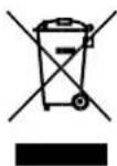
2. Technical specifications
text_image
Stepping Motor MOTO MAIN BOARD ACN FAN ACL COMP. CN2 WATER2 PT RT Coil sensor Room sensor LED DISPLAY Water Level Sensor Water pump Blue Red Red White Terminal Board L L C N N Blue Brown Blue GN/YW ~220V-240V50Hz L N E White Yellow Black Red Blue Fan Motor Fan Motor GN/YW Blue Red C Black S COMP. GN/YWtext_image
Exploded view diagram of an e-metric air conditioner unit with numbered parts for identification5. Delar
Total
text_image
1 2 3 mestic- Luftutlopp
- Spjäll
natural_image
Line drawing of a portable electric heater with mesh grille and control buttons (no text or symbols)- Nätöverdrag
- Filter
Maskin
text_image
5 6 7 8 emetic 9 10 11- Spjäll
- Kontrollknapp
- Luftinloppspanel
- Luftintag
- Handtag
- Nedre fäste
- Stötsäker gummidyna
- Bakre käpa
- Flexibel slang
text_image
Technical diagram of a device with numbered parts labeled for identificationtext_image
Technical diagram of a mechanical device with labeled parts 5 and 6, showing components like a vertical support and mounting bracket.natural_image
Technical line drawing of a mechanical bracket assembly before and after transformation (no text or symbols)natural_image
Technical line drawing of a mechanical device with an inset view showing its internal components (no text or symbols present)natural_image
Simple line drawing of an oval shape with a rectangular panel and four small circular elements inside (no text or symbols)7. Användning
- Ström på
text_image
Diagram showing three stages of an electric air heater with labeled components and airflow direction arrowsnatural_image
Line drawings of two electric blower units connected by a screwdriver, showing front and side views (no text or symbols)
2. Technical specifications
text_image
Stepping Motor MOTO MAIN BOARD ACN FAN ACL COMP. CN2 WATER2 PT RT Room sensor LED DISPLAY Water Level Sensor Coil sensor Blue Red Red White Water pump ~220V-240V50Hz Brown Blue GN/YW L N E White Yellow Black Red Blue Fan Motor Terminal Board L C N Blue Red Brown White Fan Motor GN/YW Blue Red C C Black S R COMP. GN/YW4. Pakkeliste
text_image
Exploded view diagram of an air conditioner unit with numbered parts for identification5. Deler
Totalt
text_image
1 2 3 mestic- Luftuttak
- Luftelem
natural_image
Line drawing of a portable electric heater with labeled ports and panel (no text or symbols beyond branding)- Nettdeksel
- Filter
Maskin
text_image
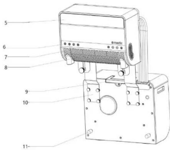
5 6 7 8 emetic 9 10 11- Luftelem
- Betjeningsknapp
- Luftinntaksplate
- Luftinntak
- Håndtak
- Nedre brakett
- Støtsikker gummipute
- Bakdeksel
- Fleksibel slange
text_image
Technical diagram of a device with numbered parts labeled for identificationtext_image
Technical diagram of a mechanical device with labeled parts 5 and 6, showing components like a vertical support and mounting bracket.- Støtsikker gummipute
- Händstrammelås
- Nedre brakett
Kontrollpanel
text_image
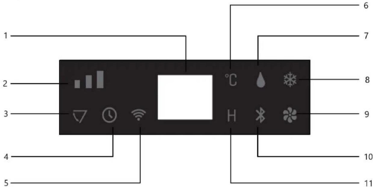
1 2 3 4 5 6 7 8 9 10 11 °C H- Digital indikatorlampe
- Viftehastighets-indikatorlampe
- Svingblad-indikatorlampe
- Timerfunksjon-indikatorlampe
- Wi-Fi-indikatorlampe
-
Celsiusgrad-indikatorlampe
-
Avfuktingsmodus-indikatorlampe
- Kjølemodus-indikatorlampe
- Viftemodus-indikatorlampe
- BLUETOOTH-modus-indikatorlampe
- Tidsymbol-indikatorlampe
Frontpanel
text_image
1 2 3 4 5 6 7 8natural_image
Technical line drawing of a mechanical bracket assembly before and after modification (no text or symbols)natural_image
Technical line drawing of a mechanical device with an inset view showing its assembly (no text or symbols present)natural_image
Simple line drawing of an oval shape with a rectangular panel and four small cylindrical objects on its surface (no text or symbols)7. Bruk
- Slå på strømmen
natural_image
Line drawing of a portable air conditioner unit with ventilation grilles and control buttons (no text or symbols)
natural_image
Line drawing of a portable air conditioner unit with ventilation grilles and control buttons (no text or symbols)
natural_image
Line drawing of a portable air conditioner unit with control panel and ventilation grilles (no text or symbols)natural_image
Line drawings of two Mertz devices connected by a screwdriver, showing front and side views (no text or symbols)