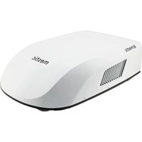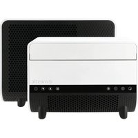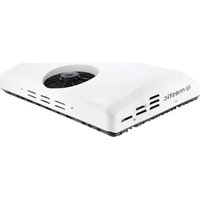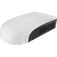
RTA-2500L - Air Conditioning Mestic - Free user manual and instructions
Find the device manual for free RTA-2500L Mestic in PDF.


| Product type | Roof air conditioning for recreational vehicles |
| Brand | Mestic |
| Model | RTA-2500L |
| Cooling capacity | 2500 W (8530 BTU) |
| Heating capacity | 2750 W (9383 BTU) |
| Cooling power | 1118 W |
| Heating power | 1135 W |
| Current (cooling/heating) | 4.3 A / 4.4 A |
| Electrical supply | 230 V ~ 50 Hz, single-phase |
| Refrigerant | R290 (220 g) - flammable gas |
| Airflow | 350 m³/h |
| Interior unit dimensions (L x W x H) | 67 x 52.3 x 5 cm |
| Exterior unit dimensions (L x W x H) | 96 x 58.5 x 25.9 cm |
| Net weight (interior/exterior) | 3 kg / 33 kg |
| Insulation class | IPX4 |
| Operating temperature range | Cooling: 18 to 46 °C / Heating: -5 to 24 °C |
| Operating modes | Auto, Cool, Heat, Fan, Night (Sleep) |
| Control | Wireless remote control, wall control panel, Mestic app (WiFi/Bluetooth) |
| Filter | Washable HEPA filter (annual replacement recommended) |
| Required roof opening | 380 x 380 mm, 390 x 390 mm or 400 x 400 mm |
| Applicable roof thickness | 30 to 80 mm |
| Protection | 10 A circuit breaker, automatic shutdown in case of fault |
| Safety | Mandatory grounding, flammable gas R290, storage in room >4 m² without ignition source |
| Included accessories | Remote control, AAA batteries (2), mounting plate, sealing foam, screws, manual |
| Repairability | Spare parts available from the manufacturer (contact authorized service) |
Frequently Asked Questions - RTA-2500L Mestic
User questions about RTA-2500L Mestic
0 question about this device. Answer the ones you know or ask your own.
Ask a new question about this device
Download the instructions for your Air Conditioning in PDF format for free! Find your manual RTA-2500L - Mestic and take your electronic device back in hand. On this page are published all the documents necessary for the use of your device. RTA-2500L by Mestic.
USER MANUAL RTA-2500L Mestic
text_image
8530 BTU/h (2500 W) 53 dB sleep mode 3 speeds KG Roof unit 33 kg @mesticUser instructions EN
User instructions English 95
Roof Top Air Conditioner
flowchart
graph TD
    subgraph MAIN_BOARD
        direction TB
        A["OUTDOOR TUBE SENSOR"] --> B["(WH)"]
        C["TUBE SENSOR"] --> D["(RD)"]
        E["ROOM SENSOR"] --> F["(YE)"]
        G["4-WAY VALVE"] --> H["VT BU"]
        I["4YV"] --> J["VT BU"]
        K["CAP."] --> L["C1"]
        M["IN_FAN MOTOR"] --> N["M1"]
        O["YEGN"] --> P["FAN"]
        Q["PE"] --> R["OUT_FAN MOTOR"]
    end

    subgraph MAIN_BOARD
        S["MAIN BOARD"] --> T["POWER"]
        U["L N"] --> V["BN BU"]
        W["BEGN"] --> X["ACN1 ACN2"]
        Y["ACL"] --> Z["K1 COMP"]
        AA["COMP"] --> AB["K2 BK"]
        AC["COMP."] --> AD["PE"]
        AE["PE"] --> AF["RD"]
        AG["R"] --> AH["COMP"]
        AI["BYGN"] --> AJ["COMP"]
    end

    subgraph MAIN_BOARD
        AK["OFAN"] --> AL["BN BU RD YE BK WH"]
        AM["OFAN_C"] --> AN["BU RD YE BK WH"]
        AO["M2 OUT_FAN MOTOR"] --> AP["YEGN PE"]
    end
PAKLIJST
 1 1 | 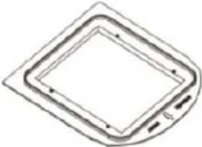 2 2 | 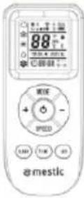 3 3 | 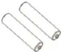 4 4 |
| [ADSW]5 | 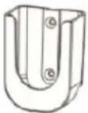 6 6 |  7 7 |  8 8 |
 9 9 |  10 10 | 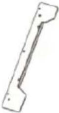 11 11 | 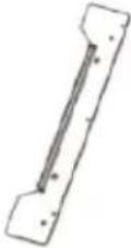 12 12 |
 13 13 |  14 14 | 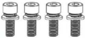 15 15 | 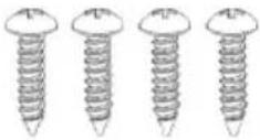 16 16 |
text_image
Technical diagram of a portable electronic device with numbered components and a digital remote control panel labeled 'EMSTIC'.text_image
Technical diagram of a device with numbered components, showing front and side views with labeled parts.text_image
Operation mode 88:00 88:88 S-1 S-0Ventilatorsnelheid
Verzenden-signaal
Automatische modus
Koelmodus
Verwarmingsmodus
Ventilatormodus
Stand-bymodus
Lampje
Tijd
Timer AAN/UIT
INTRODUCTIE VOOR KNOPPEN OP AFSTANDSBEDIENING
Opmerking:
text_image
QR code image containing encoded data, no visible human-readable textINSTALLATIE-INSTRUCTIE
VOOR DE INSTALLATIE
text_image
Figure 1-2LET OP
text_image
Figure 4.1text_image
① Fig 6 ②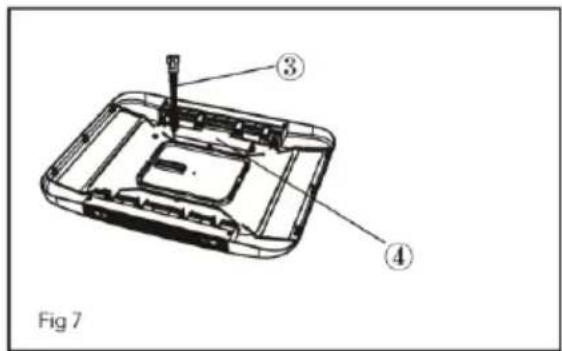
text_image
Fig 7natural_image
Technical line drawing of a mechanical assembly with no visible text or symbols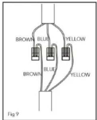
text_image
BROWN BLUE YELLOW BROWN BLUE YELLOW Fig 9natural_image
Technical line drawing of a mechanical component with no visible text or symbols27
natural_image
Simple line drawing of a mechanical component with wires, labeled Fig 8.2 (no text or symbols on the diagram itself)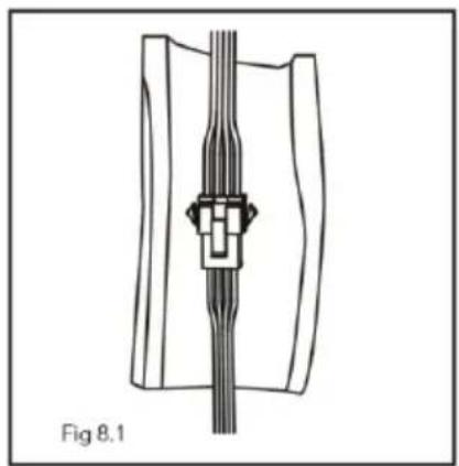
natural_image
Technical line drawing of a mechanical component with no visible text or symbols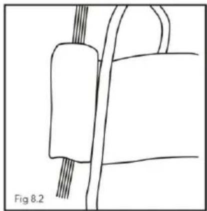
natural_image
Simple line drawing of a mechanical component with wires, labeled Fig 8.2 (no text or symbols on the diagram itself)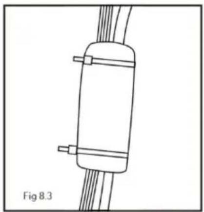
natural_image
Diagram of a cylindrical device with two connectors and coiled wires, labeled Fig 8.3 (no text or symbols on the diagram itself)NOTE
text_image
Technical diagram of a ventilation system with numbered components for identificationnatural_image
Technical line drawing of a car air conditioner unit with internal components and mounting base (no text or symbols)text_image
pull pull ① ② ③ ② ①ET PAR ORD OM DIT NYE KLIMAANLÆG
text_image
Technical diagram of a device with numbered components and a digital display showing 88°C reading.① Udluftningsgitter
text_image
Technical diagram of a device with numbered components, showing front and side views with labeled parts.text_image
Operation mode 0-1 0-0Ventilatorhastighed
Send signal
Auto-modus
Køle-modus
Varme-modus
Ventilator-modus
Sleep-modus
Lys
Temperatur
Tid
Tænd/sluk-timer
INTRODUKTION TIL KNAPPER PÅ FJERNBETJENINGEN
Bemærk:
text_image
QR code image containing encoded data, no visible human-readable textINSTALLATIONSVEJLEDNING
F∅R INSTALLATION
natural_image
Technical line drawing of a device casing with internal components and labeled part (1), no readable text or symbols present.text_image
Technical diagram of a solar panel installation with 5° and 0° angles labeledtext_image
Figure 4.1text_image
Technical diagram of a device with numbered components, showing internal structure and assembly stepstext_image
Figur 5-1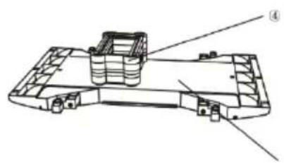
natural_image
Technical line drawing of a mechanical component with no visible text or symbolsFigur 5-2
① skum (4 mm)
② skum (20 mm)
③ skum (10 mm)
④ skum
⑤ vind-sti
ELEKTRISK LEDNINGSF∅RING
TRIN 5-ELEKTRISK LEDNINGSF∅RING
LEDNINGSF∅RING 220-240 V VEKSELSTR∅M
text_image
① Fig 6 ②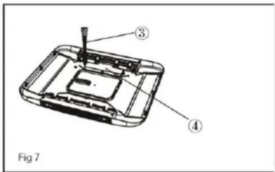
text_image
Fig 7natural_image
Technical line drawing of a mechanical component with no visible text or symbols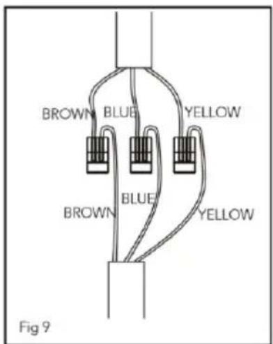
text_image
BROWN BLUE YELLOW BROWN BLUE YELLOW Fig 9natural_image
Technical line drawing of a mechanical component with no visible text or symbols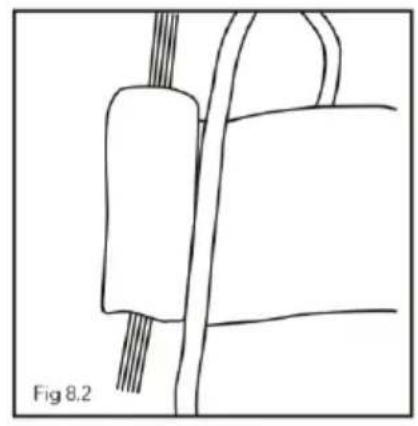
natural_image
Simple line drawing of a mechanical component with no text or symbols
natural_image
Diagram of a cylindrical tank with attached cables, labeled Fig 8.3 (no text or symbols on the diagram itself)NOTE
text_image
Technical diagram of a car air conditioning unit with numbered components for identificationnatural_image
Technical line drawing of a vehicle air vent assembly with labeled components (no text or symbols present)text_image
pull pull ① ② ③ ② ①① Net
② HEPA-filter
③ Luftindtagsgitter
SÅDAN RENGÕRES LUFTNET OG HEPA-FILTER
text_image
Technical diagram of a device with numbered components and a digital display showing temperature reading.⑨
text_image
Diagram of a device with labeled parts, showing a panel or vent and numbered annotations.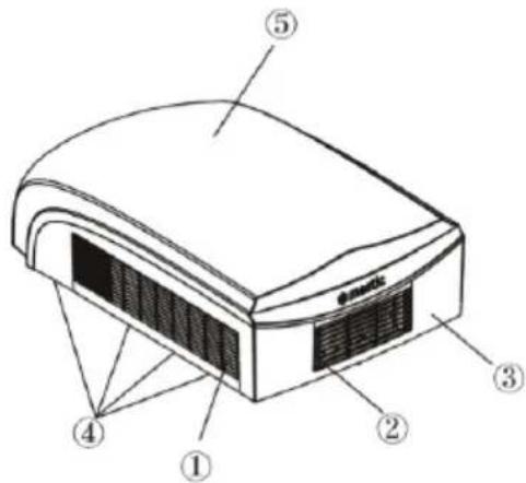
text_image
Diagram of a device with numbered parts labeled 1 through 5, likely illustrating a technical or mechanical assembly.text_image
QR code image containing encoded data, no visible human-readable textINSTALLATIONSHINWEISE
VOR DER INSTALLATION
natural_image
Technical line drawing of a device casing with internal components and a numbered label (1), no readable text or symbols present.text_image
Standard Dimension Figure 1-2VORSICHT
text_image
Figure 4.1text_image
Figure 4.2SCHRITT 4 - INSTALLATION DER DECKENEINHEIT
BEACHTEN SIE:
text_image
Technical diagram of a device with numbered components, showing internal structure and assembly stepstext_image
① Fig 6 ②natural_image
Technical line drawing of a mechanical assembly with no visible text or symbols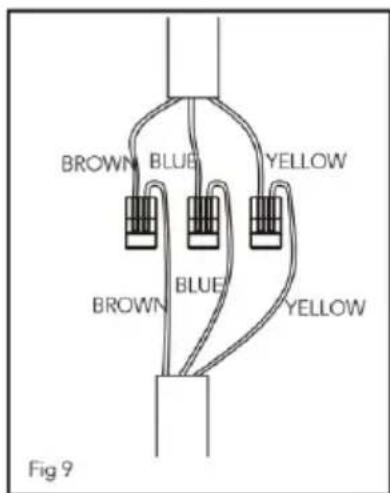
text_image
BROWN BLUE YELLOW BROWN BLUE YELLOW Fig 9natural_image
Technical line drawing of a mechanical component with no visible text or symbols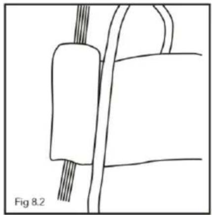
natural_image
Simple line drawing of a mechanical component with wires, labeled Fig 8.2 (no text or symbols on the diagram itself)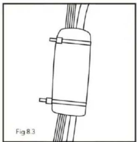
natural_image
Simple line drawing of a cylindrical device with two connectors and coiled wires, labeled Fig 8.3 (no text or symbols on the diagram itself)NOTE
text_image
Technical diagram of a car air conditioning unit with numbered components for identificationnatural_image
Technical line drawing of a vehicle air duct system with internal components and mounting bracket (no text or symbols)text_image
pull pull ① ② ③ ② ①
Gitter

HEPA-Filter

Lufteinlassgitter
WIE MAN DAS LUFTGITTER UND DEN HEPA-FILTER REINIGT
User instructions English
A few words about your new air conditioning unit 96
Installation precaution 97
Electrical data 99
Technical data 100
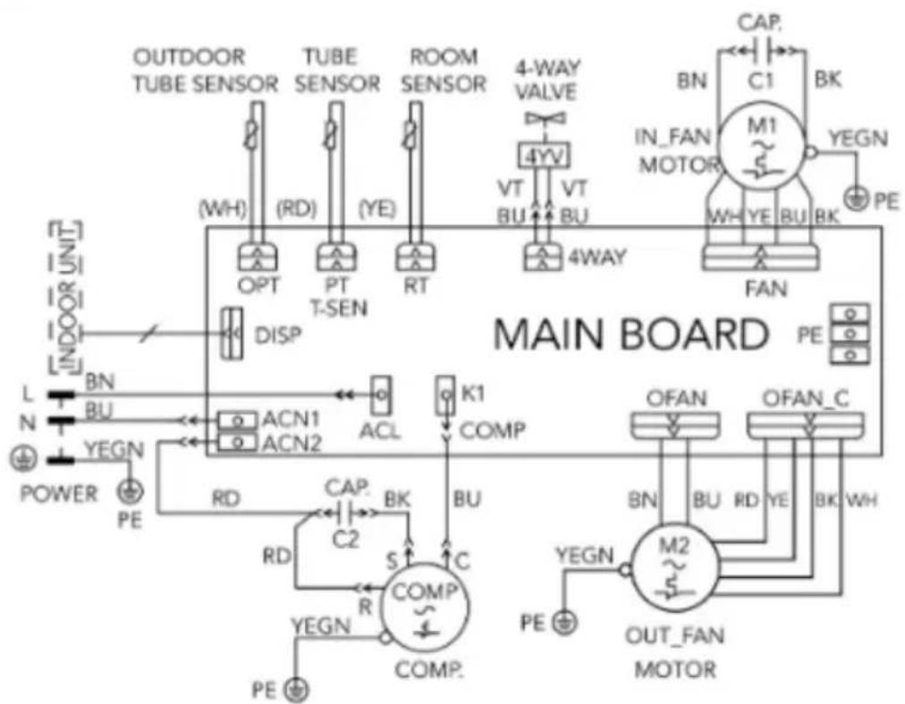
Electric diagram 101
Packing list 102
Parts name 103
Operation of wireless remote controller 104
Control panel 108
Connecting to the Mestic app 109
Installation instruction 110
Step 1 - Sticking the sealing strip and sponge pieces on the outdoor unit 110
Step 2 - selecting an installation location & 111 installing the roof top air conditioner
Step 3 - mounting outdoor unit 114
Step 4 - installing the ceiling assembly 115
Step 5 - electrical wiring 118
Step 6 - completing the installation 119
Disassembly 120
Troubleshooting guide 121
Error codes 122
Regular maintenance procedures 123
Recycling 124
A FEW WORDS ABOUT YOUR NEW AIR CONDITIONING UNIT
Thank you for choosing the Recreational Vehicle Air Conditioner. This manual will supply you with all the information for installation, operation and maintenance. Take a few minutes to discover how to get the most in cooling comfort and economic operation from your new air conditioner. Please keep this manual well for future reference. An all-pole disconnection switch having a contact separation of at least 3mm in all poles should be connected in fixed wiring. As well as an circuit breaker with the capacity of 10A. The circuit breaker should include a magnetic and thermal release function, so it can protect against short-circuiting and overloading.
WARNING:
- This appliance is not intended for use by persons (including children) with reduced physical, sensory or mental capabilities, or lack of experience and knowledge, unless they have been given supervision or instruction concerning use of the appliance by a person responsible for their safety. Children should be supervised to ensure that they do not play with the appliance.
This appliance can be used by children aged from 8 years and above and persons with reduced physical, sensory or mental capabilities or lack of experience and knowledge if they have been given supervision or instruction concerning use of the appliance in a safe way and understand the hazards involved.
• Children shall not play with the appliance.
• Cleaning and user maintenance shall not be done by children without supervision and only after reading the - When the refrigerant leaks or requires discharge during installation, maintenance, or disassembly, it should be handled by certified professionals and/or in compliance with local laws and regulations.
INSTALLATION PRECAUTION
WARNING:
- Observe all governing codes and ordinances.
- Do not use damaged or non-standard power cord.
• Make sure wires are insulated properly and protected against abrasion. - Be caution during installation and maintenance. Prohibit incorrect operation to prevent electric shock, casualty and other accidents.
- Before turning on the unit, please open the horizontal louver of indoor unit by hand. Otherwise, the cool air can't be blown out and there will be condensate water on the horizontal louver.
• The appliance contains the flammable gas R290. - Be aware that refrigerants may be odourless.
• The appliance shall be installed, operated and stored in a room with a floor area larger than 4 m². - The appliance shall be stored in a room without continuously operating ignition sources. (For example: open flames, an operating gas appliance or an operating electric heater.)
• The appliance shall be stored in such a way as to prevent mechanical damage from occurring. - Keep any ventilation openings clear of obstruction.
• Do not use means to accelerate the defrosting process or to clean, other than those recommended by the manufacturer. - Should repair be necessary, contact your nearest authorized service centre. Any repairs carried out by unqualified personnel may cause dangerous situations.
Working temperature range
Suggested working temperature range: -5 \~ 46°C. (heating:-5\~24°C/cooling:+18\~46 °C). The outdoor unit may stop operating, due to various kinds of protection within the working temperature range.
Selection of Installation Location
Basic requirement
Installing the unit in the following places may cause malfunction. If it is unavoidable, please consult the local dealer:
- Near strong heat sources, vapours, flammable or explosive gas, or volatile objects spread in the air.
- Near high-frequency devices (such as welding machine, medical equipment).
- In a coastal area.
- In an area with oil of fumes in the air.
- An area with sulfureted gas.
- Any other place with special circumstances.
- This air conditioner unit is only used for the vehicle without concave and convex roof top.
- Do not operate this air conditioner unit when starting up the vehicle or when the vehicle is driving.
- Do not supply the power for the air conditioner unit with the vehicle power supply.
Requirement of air conditioner
- Air inlet should be far away from obstacles and do not put any objects near air outlet. Otherwise, it will affect the radiation of heat-removal pipe.
- Select a location where the noise and outflow air emitted by the outdoor unit will not affect the surrounding area.
- Mount the unit far away from fluorescent lamps.
- The appliance shall not be installed in the bathroom.
INSTALLATION PRECAUTION
Requirements for electric connection
Safety precaution
- Must follow the electric safety regulations when installing the unit.
- According to the local safety regulations, use qualified power supply circuit.
- If the supply cord is damaged, it must be replaced by the manufacturer, its service agent or similarly qualified persons in order to avoid a hazard.
- Properly connect the live wire, neutral wire and grounding wire of power socket.
- Be sure to cut off the power supply before proceeding any work related to electricity and safety.
- Do not put on the power before finishing installation.
- the air conditioner is first class electric appliance. It must be properly grounding. With specialized grounding device by a professional. Please make sure it is
- The yellow-green wire or green wire in air conditioner is grounding wire, which can't be used for other purposes.
- The grounding resistance should comply with national electric safety regulations.
- The appliance shall be installed in accordance with national wiring regulations.
ELECTRICAL DATA
- All wiring must be complied with local and national electrical codes. All wiring must be installed by qualified electricians. If you have any questions about the following instructions, contact a qualified electrician.
- Check the available power supply and resolve any wiring problems BEFORE installing and operating this unit.
- This air conditioner is designed to operate from a 220-240V AC, 50Hz, 1 Phase power supply.
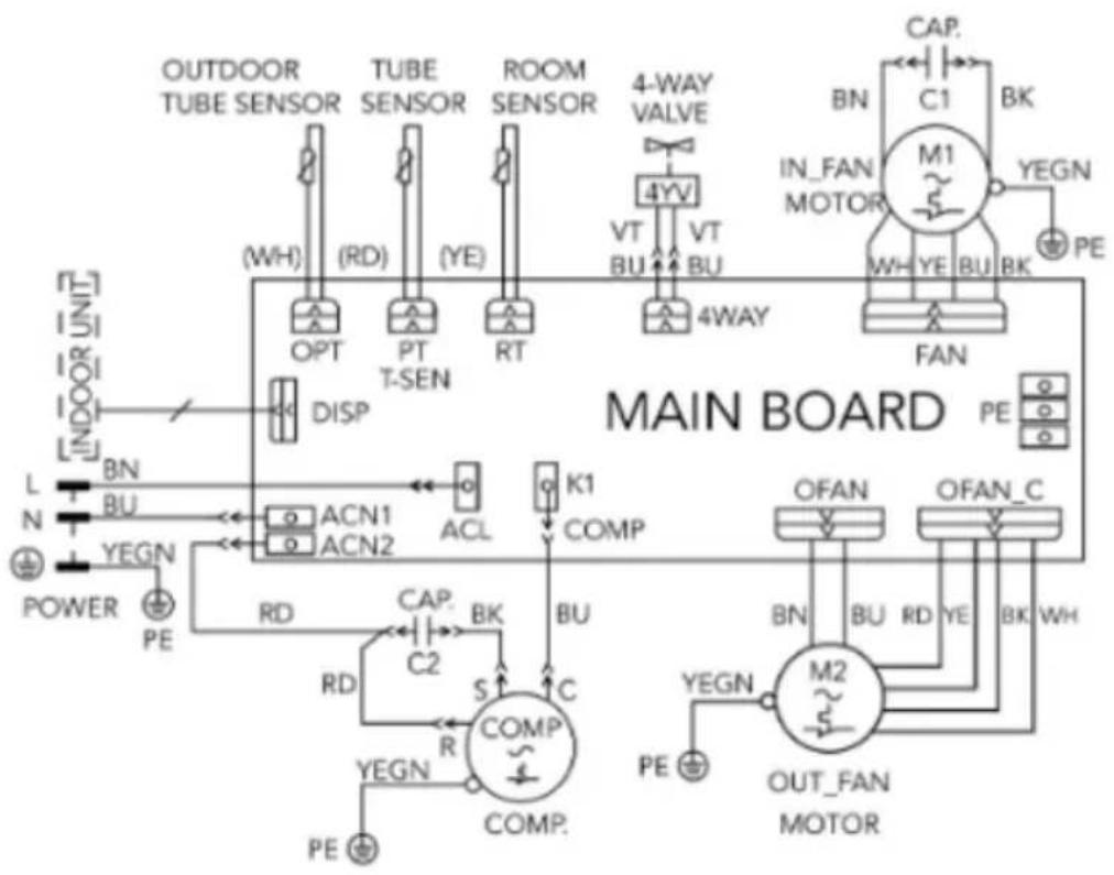
- The wiring diagrams are can be found in this manual.
- If the supply cord is damaged, it must be replaced by the manufacturer, its service agent or similarly qualified persons in order to avoid a hazard.
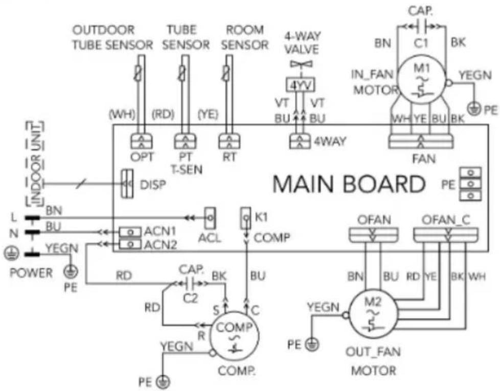
- The Electric schematic diagram are subject to change without notice. Please refer to the one delivered with the unit.
TECHNICAL DATA
| Model | RTA2500L | Heating input Current | 4.4A |
| function | cold and hot | Cooling input power | 1118W |
| Cooling capacity | 8530 BTU (2500W) | Heating input power | 1135W |
| Heating capacity | 9383 BTU (2750W) | Isolation class | IPX4 |
| Air flow capacity | 350m^3/h | Net weight (internal/external) | 3/33kg |
| Refrigerant | R290(220g) | Dimensions inside unit | 67×52.3×5cm |
| Voltage | 230V 50Hz | Dimensions outside unit | 96×58.5×25.9cm |
| Cooling input Current | 4.3A |
ELECTRIC DIAGRAM
Ceiling Assembly
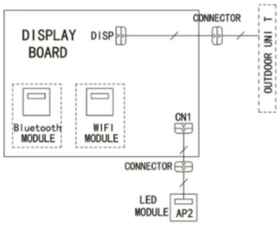
flowchart
graph TD
    A["DISPLAY BOARD"] --> B["DISP"]
    B --> C["CONNECTOR"]
    C --> D["OUTDOOR UNI T"]
    E["Bluetooth MODULE"] --> F["CN1"]
    G["WIFI MODULE"] --> H["CONNECTOR"]
    I["LED MODULE"] --> J["AP2"]
    F --> H
    H --> J
Roof Top Air Conditioner
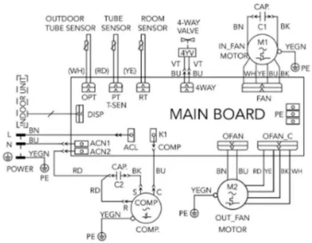
flowchart
graph TD
    A["OUTDOOR TUBE SENSOR"] --> B["(WH)"]
    C["TUBE SENSOR"] --> D["(RD)"]
    E["ROOM SENSOR"] --> F["(YE)"]
    G["4-WAY VALVE"] --> H["VT BU"]
    I["4YV"] --> J["VT BU"]
    K["CAP."] --> L["C1"]
    M["M1"] --> N["IN_FAN MOTOR"]
    O["PE"] --> P["FAN"]
    Q["L N POWER"] --> R["BN BU"]
    S["YEGN PE"] --> T["ACN1 ACN2"]
    U["RD"] --> V["CAP. BK"]
    W["RD"] --> X["C2"]
    Y["YEGN PE"] --> Z["COMP. COMP."]
    AA["S"] --> AB["K1 COMP"]
    AC["S"] --> AD["K1 COMP"]
    AE["C"] --> AF["COMP. COMP."]
    AG["BU"] --> AH["COMP. COMP."]
    AI["PE"] --> AJ["OUT_FAN MOTOR"]
    AK["PE"] --> AL["OUT_FAN MOTOR"]
    AM["ON"] --> AN["ON"]
    AO["ON"] --> AP["ON"]
    AQ["ON"] --> AR["ON"]
    AS["ON"] --> AT["ON"]
    AU["ON"] --> AV["ON"]
    AW["ON"] --> AX["ON"]
    AY["INDOOR UNIT"] --> AZ["DISP"]
    BA["MAIN BOARD"] --> BB["OPEN/CONTROL MODE"]
    BC["OPEN/CONTROL MODE"] --> BD["OPEN/CONTROL MODE"]
    BE["OPEN/CONTROL MODE"] --> BF["OPEN/CONTROL MODE"]
PACKING LIST
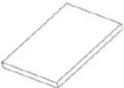 1 1 | 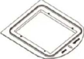 2 2 | 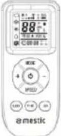 3 3 | 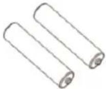 4 4 |
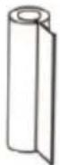 5 5 | 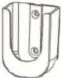 6 6 | 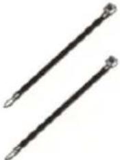 7 7 | 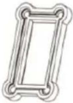 8 8 |
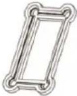 9 9 | 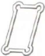 10 10 | 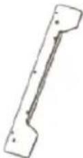 11 11 | 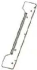 12 12 |
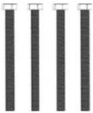 13 13 |  14 14 | 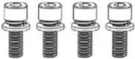 15 15 | 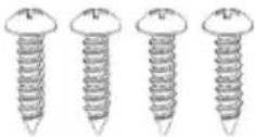 16 16 |
- Owner's manual (1)
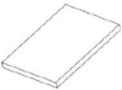
- Mounting plate (1)
- Remote controller (1)
- Battery (AAA 1.5V) (2)
- Insulating tape (1)
- Remote controller holder (1)
-
Bundle (2)
-
Styrofoam (accessory 20mm) (3)
- Styrofoam (accessory 10mm) (2)
- Soft foam (foam accessory) (4)
- Left mounting plate sub-assembly (1)
- Right mounting plate sub-assembly (1)
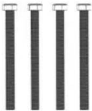
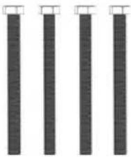
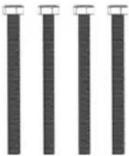
- Bolt sub-assembly M6X75 (4)
-
Foam (3)
-
Bolt sub-assembly M5X12 (4)
- Tapping screw ST4X20 (4)
PARTS NAME
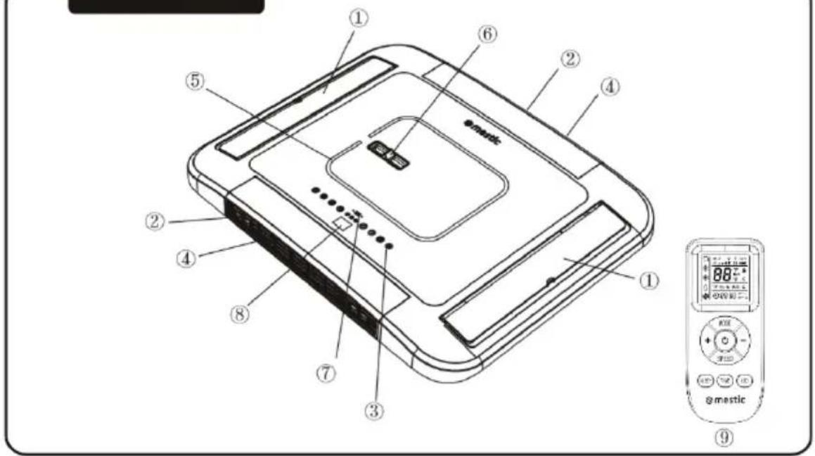
Indoor Unit
text_image
Technical diagram of a device with numbered components and a digital display showing 88% AC power.① Air-out grille ② Air-in grille ③ Control panel (membrane) ④ Filter sub-assembly ⑤ LED indicator
⑥ Operating handle ⑦ Remote receiver window ⑧ Setting temperature ⑨ Remote controller
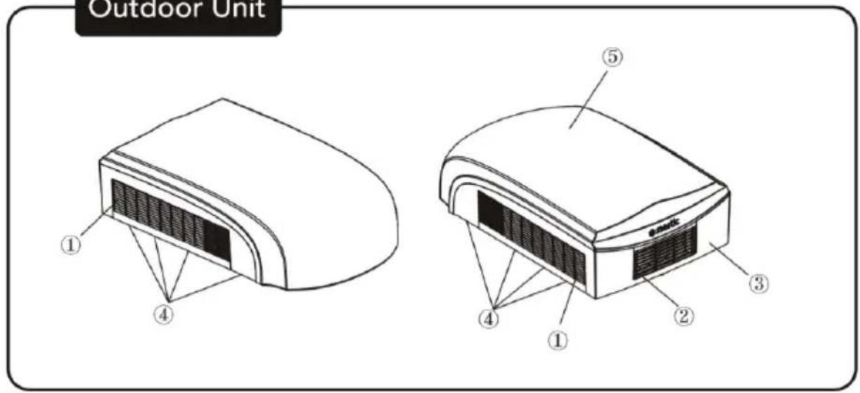
Outdoor Unit
text_image
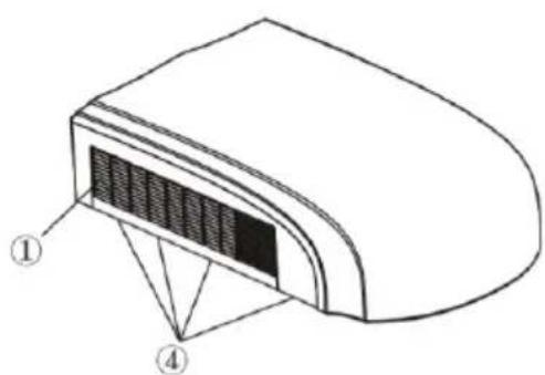
Outdoor Unit ① ④ ⑤ ③ ② ④ ①① Air-in grille ② Air-out grille ③ Frame ④ Drainage outlet ⑤ Outer case
Notice:
Actual products may be different from above graphics, please refer to actual products.
text_image
0-1 88-88 88-88 0-1 ebom noise 0-1Fan speed
Send signal
Auto mode
Cool mode
Heat mode
Fan mode
Sleep mode
Light
Temperature
Time
Timer ON/OFF
INTRODUCTION FOR BUTTONS ON REMOTE CONTROLLER
Note:
- After turning on the power, the air conditioner will give out a sound and the operation indicator "RUN" is on. Now, you can operate the air conditioner through the remote controller.
- When the power is on, every time a button is pressed on the remote controller, the signal icon “ 🍴 ” on the remote controller will flash once. The air conditioner will give out a sound, which indicates the signal has been sent to the air conditioner.
1. On/off button
- Press this button to turn the air conditioner on. Press this button again to turn the air conditioner off.
2. Mode button
- Press this button to select your required operation mode.

flowchart
graph LR
    A["AUTO"] --> B["COOL"]
    B --> C["HEAT"]
    C --> D["FAN"]
- In "AUTO" mode, the air conditioner will automatically operate according to the ambient temperature. The set temperature cannot be changed and will not be displayed. By pressing the "FAN" button, the fan speed can be adjusted.
- In "COOL" mode, press the "+" or "-" button to change the set temperature. To adjust the fan speed, press the "FAN" button.
- In "FAN" mode, only the fan is turned on, without any cooling or heating. Press the "FAN" button, to adjust the fan speed.
- In "HEAT" mode, press the "+" or "-" button to change the set temperature. To adjust the fan speed, press the "FAN" button
Note:
- After the "HEAT" mode is selected, the air conditioner will delay air blowing 1-5 minutes, to prevent blowing cold air. The actual delay time depends on the indoor ambient temperature.
• The temperature can be set between 16-31°C (61-88°F).
3. Speed button
• This button is used for setting the fan speed in the following sequence:
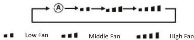
flowchart
graph LR
    A["Low Fan"] --> B["Intermediate Stage"]
    B --> C["High Fan"]
Note:
- In “ speed mode, the air conditioner will automatically select the proper fan speed according to the default setting.
4. “+” button
- Press the “+” button once to increase the set temperature by 1°C (°F). Hold the “+” button down for at least 2 seconds, and the set temperature will change quickly. Once the “+” button is released after setting the temperature, the temperature indicator on the air conditioner will change accordingly. The temperature cannot be adjusted in “AUTO” mode.
- When setting the "TIMER ON" or the "TIMER OFF" or the "CLOCK", press the "+" button to adjust the time. Look for more information under 'Timer on function', 'Timer off function'.
5. "-" button
- Press the “-” button once to decrease the set temperature by 1°C (°F). Hold the “-” button down for at least 2 seconds, and the set temperature will change quickly. Once the “-” button is released after setting the temperature, the temperature indicator on the air conditioner will change accordingly. The temperature cannot be adjusted in “AUTO” mode.
- When setting the "TIMER ON" or the "TIMER OFF" or the "CLOCK", press the "-" button to adjust the time. Look for more information under 'Timer on function' and 'Timer off function'.
6. "TIME" button
- Press the "TIME" button to switch between "TIMER ON" and "TIMER OFF". With the "TIMER ON" function, the time for timer on can be set. When the "TIMER ON" function is active, the symbol " 🔍 → ↑" flashes on the remote controller.
This symbol “ 88:88” is displayed. Press the “+” or “-” button to adjust the “TIMER ON” setting.
By pressing the button "+" or "-" the setting will increase or decrease with 1 minute at a time.
Hold the "+" or "-" button for 2 seconds, the time setting will now change quickly until the required time is reached.
Press the "TIME" button 5 seconds to confirm the new setting. The symbol "→" will stop flashing.
To cancel "TIMER ON": when the "TIMER ON" function has been selected and the symbol "→|" flashes on the remote controller, press the "TIME" button until the symbol "→|" and "88:88" disappear.
- With the "TIMER OFF" function, the time for "TIMER OFF" can be set. When the "TIMER OFF" function is active,
the symbol “→” flashes on the remote controller. This symbol “88:88” is displayed. Press the “+” or “-” button to adjust the timer off setting. By pressing the button “+” or “-”, the setting will increase or decrease with 1 minute at a time.
Hold the "+" or "-" button for 2 seconds, the time setting will now change quickly until the required time is reached.
Press the "TIME" button for 5 seconds to confirm the new setting. The symbol "→o" will stop flashing.
To cancel "TIMER OFF": when the "TIMER OFF" function has been selected and the symbol "→o" flashes on the remote controller, press the "TIME" button until the symbols "→o" and "88:88" disappear.
7. Sleep button
Press the "SLEEP" button and the symbol "C" will light up. In sleep mode the fan speed will go to the lowest setting and all the lights will go off. Press the "SLEEP" button again and the symbol "C" will go out and the aircon will operate in normal modus.
8. LED button
Press the "LED" button, the symbol " 🔍" lights up and turns on the warm white light of the indoor unit, press the "LED" button again, the symbol " 🔍" is still displayed and turns on the cold white light of the indoor unit. Press the LED button again, the symbol " 🔍" goes off and turns off the light of the indoor unit.
Note:
- During operation, point the signal sender of the remote controller at the receiving unit. The distance between the signal sender and the receiving unit should be no more than 8 meters, and there should be no obstacles in between.
- The signal of the remote controller may be interfered when there is a fluorescent lamp or wireless telephone in the room. The remote controller should be close to the unit during operation.
- When replacing the batteries is required, use new batteries of the same model. If the remote controller is not used for a long time, please take out the batteries.
• If the display on the remote controller is blurry or nothing is displayed at all, please replace the batteries.
Replacement of batteries in the remote controller
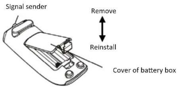
text_image
Signal sender Remove Reinstall Cover of battery box
- Move the battery cover with your finger and open the battery cover in the direction of the arrow.
- Replace the two dry batteries (AAA 1.5V) and make sure the position of the "+" and "-" poles are correct.
- Reinstall the cover of the battery box.
CONTROL PANEL
Note: If the remote controller is missing, operate on the control panel.
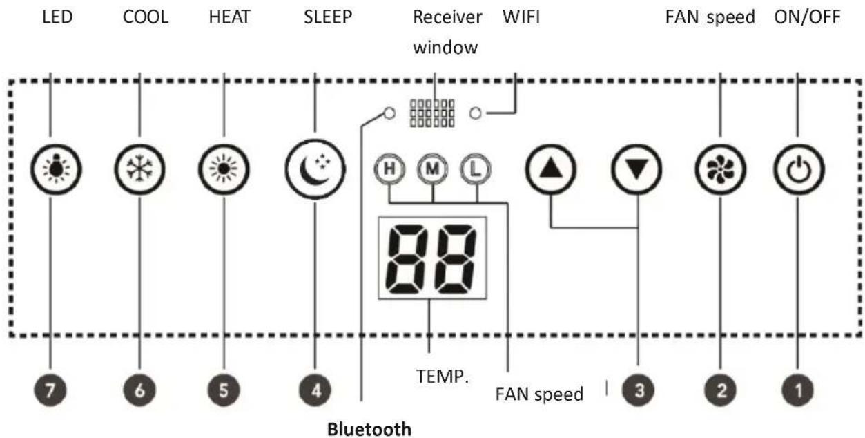
text_image
LED COOL HEAT SLEEP Receiver WIFI window FAN speed ON/OFF 7 6 5 4 88 TEMP. Bluetooth FAN speed 3 2 11. ON/OFF button
Operation starts when pressing this button, and stops when pressing this button again.
2. FAN speed button
Select the fan speed LOW, MED, HIGH. The boot state is MED.
3. ( ▲▼ button
Press the "▲" button to increase the set (operating) temperature of the unit, and press the "▼" button to decrease the set (operating) temperature of the unit. The temperature setting range is from 16\~31°C (61\~88°F).
4. SLEEP button
Press the "SLEEP" button. The sleep indicator will light up and starts sleep mode. After several seconds, all the indicators on the panel go out. Turn off sleep mode by pressing any button on the panel.
5. HEAT button
Press the "HEAT" button. the HEAT indicator will light up and starts heating mode. Press the "HEAT" button again. The HEAT indicator will go out and turn off heating mode.
6. COOL button
Press the "COOL" button. The COOL indicator will light up and starts cooling mode. Press the "COOL" button again. The COOL indicator will go out and turn off cooling mode.
7. LED button
Press this button to turn on or turn off display light on indoor unit.
8. WIFI indicator
In the default state, the WIFI indicator blinks and when connection to the network is successful the WIFI indicator is steady on.
9. Bluetooth indicator
In the default state, the Bluetooth indicator blinks. When connection to a device is successful, the Bluetooth indicator is steady on.
APP
The app allows you to manage and view information and data about this product. For detailed usage instructions, please refer to the instructions for Bluetooth or WiFi connection:

text_image
QR code image containing encoded data, no visible human-readable textINSTALLATION INSTRUCTION
BEFORE INSTALLATION
Test run the unit with proper power supply. Check the operation instruction section in the Owner's Manual Operation & Installation. Make sure all the controls operate correctly then disconnect the power supply of the unit.
WARNING
- Moving parts may cause personal injury. Be careful when test the unit. Do not operate the unit with exterior cover removed.
- The outdoor unit can't be installed in a lower recess of the roof of the vehicle. It must be mounted at a flat surface on the roof to make sure the rain, car-washing water, condensation water etc. can be drained smoothly. Water shouldn't be able to accumulate around the outdoor unit. Otherwise, it will cause malfunction or safety hazards as the water will enter the air conditioner.
- Please use the supplied mounting plate to install the outdoor unit. Otherwise, it may cause malfunction or damage.
- Please use the adapter when the opening is 390mm x390mm or 400mm x 400mm.
STEP 1 – STICKING THE SEALING STRIP AND SPONGE PIECES ON THE OUTDOOR UNIT
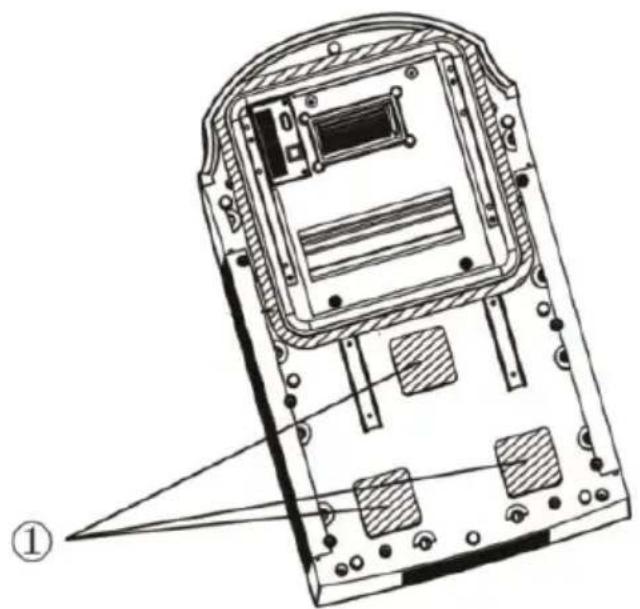
- Before sticking the sealing strip and sponge pieces to the underside of the outdoor unit, clean the sticking areas shown in figure 1.
- Take out the sealing strip and the sponge pieces from the packaging, pull off the paper on the glue surface and align them at the sticking positions as shown in Figure 1. If the sealing strip is damaged or not stuck on the proper position, you must replace it with a new one and stick it properly.
- Check whether the sealing strip and the sponge pieces are tightly adhered, and ensure that they will not fall off.
natural_image
Technical line drawing of a device rear panel with internal components and labeled part (1), no readable text or symbols present.Figure 1
1) Sticking position of three pieces of foam
STEP 2-SELECTING AN INSTALLATION LOCATION & INSTALLING THE ROOF TOP AIR CONDITIONER
Your air conditioner has been designed for use in recreational vehicles. Check the roof of the vehicle to determine if it can support both the roof top unit and the ceiling assembly without additional support. Make sure the interior ceiling mounting area will not interfere with existing structures. Once the location for your air conditioner has been determined. A reinforced and framed roof hole opening must be cut (if there is no hole) or you may use existing vent holes.
CASE A.
If a roof vent is already present in the desired mounting location for the air conditioner, the following steps must be performed:
- Remove all screws which secure the roof vent to the vehicle. Remove the vent and any additional trim. Carefully remove all chalking from around the opening so the surface is clear.
- It may be necessary to seal some of the old roof vent mounting screw holes which may fall outside of the air conditioner base pan gasket.
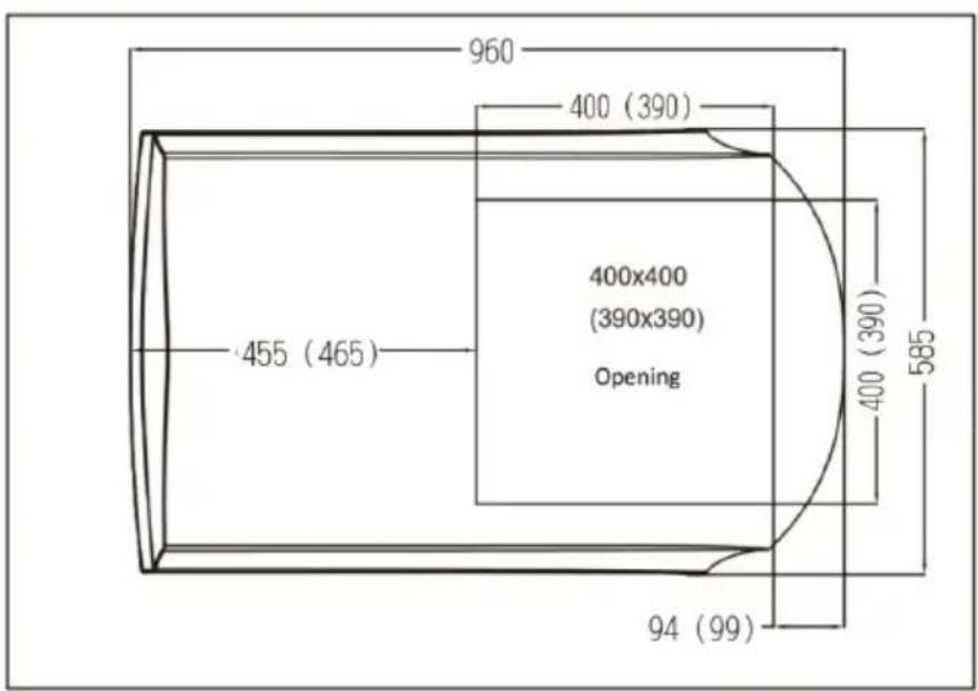
- Examine the roof opening size, if the opening is smaller than 380 x 380mm, the opening must be enlarged. The dimensions should be 380 x 380mm, 390 x 390mm or 400 x 400mm.
CASE B.
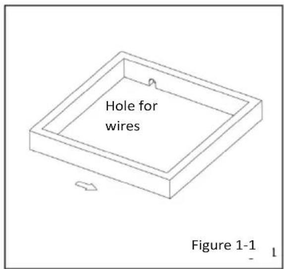
If a roof ventilation opening is not present, a new opening must be cut into the roof of the vehicle. A matching opening will also have to be cut into the ceiling inside the vehicle. Be careful as the roof piece can get stuck if the roof is multi-layered. When the opening in the roof and the ceiling are the correct size, a support structure must be fitted between the outside roof and the ceiling inside. The reinforced framework must comply with the following guidelines:
text_image
Hole for wires Figure 1-1-
It must be capable of supporting both the weight of the roof top air conditioner and the interior ceiling assembly.
-
It must be capable of holding the roof outer surface and interior ceiling apart and supporting them, so that when the roof top air conditioner and ceiling assembly are bolted together, no collapsing occurs. A typical support frame is shown in Figure 1-1.
-
There must be an opening through the frame for the power supply wiring. Route the supply wiring through the frame at the same time the support frame is being installed.
INSTALLATION METHOD OF THE MOUNTING PLATE
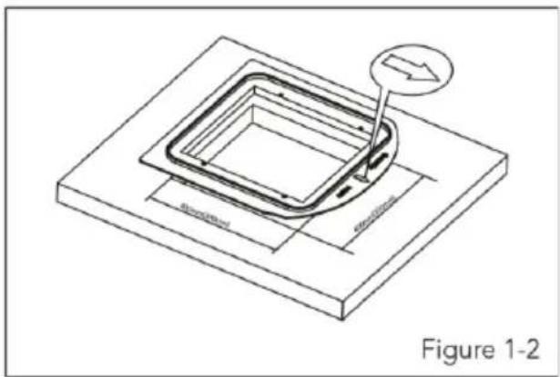
If the roof of the vehicle already has an 400x400mm or an 390x390mm opening:
- Choose the installation position for the air conditioner. The mounting adapter is suitable for an opening size of 400×400mm or 390×390mm. The 380×380mm opening is not suitable for installing the adapter.
Operation method:
• Make sure the installation surface is flat. Remove any obstacles around the opening in the roof.
- Check whether there are holes or grooves on the installation surface. If so, conduct a sealing treatment to prevent water leakage.
- Fill the groove where the mounting adapter is making contact with the roof of the vehicle with unhardened sealant (the maximum thickness is 1cm). When the mounting plate is installed on the top of the vehicle, fill the gap between the mounting plate and the vehicle roof with sealant. The mounting adapter should be sealed tightly together with the roof of the vehicle to prevent water leakage.
- Install it in the opening in the roof of the vehicle according to the direction indicated by the arrow in figure 1-2 (the direction of the arrow should point towards the front of the vehicle).
text_image
Figure 1-2CAUTION
-
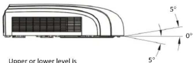
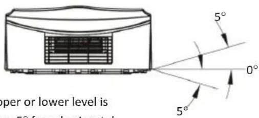
The roof top air conditioner must be mounted on a level plane from front to rear and side to side when the vehicle is parked on a level plane. Figure 2 shows maximum allowable degrees that the unit can be mounted above or below level.
-
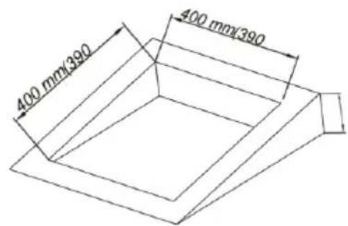
If the roof of the vehicle is sloped (not level) such that the roof top air conditioner cannot be mounted within the maximum allowable degree specifications, an exterior levelling shim will need to be added to make the unit level. A typical levelling shim is shown in Figure 3.
-
Once the roof top air conditioner has been levelled, some additional shimming may be required above the interior ceiling assembly. The roof top air conditioner and the interior ceiling assembly must be square with each other before they are secured together.
-
After the mounting hole area is properly prepared, remove the carton and shipping pads from around the roof top air conditioner. Carefully lift the unit on top of the vehicle. Do not use the outer plastic shroud for lifting. Place the roof top air conditioner over the prepared mounting hole.
-
The point end (nose) of the shroud must face toward the front of the vehicle.
Figure 2
text_image
Upper or lower level is 5° 0° 5°Upper or lower level is max. 5° from horizontal
text_image
upper or lower level is 5° from horizontalUpper or lower level is max. 5° from horizontal
Always make sure the unit is horizontal when in use. The unit can only be used for a short amount of time the maximum slope of 5^ otherwise leakage of condense water can occur.
above
text_image
400 mm/390 400 mm/390Height varies to make unit level
Figure 3
NOTE AIR CONDITIONER DIMENSIONS (ROOF OF UNIT)
text_image
960 400 (390) 455 (465) 400x400 (390x390) Opening 400 (390) 585 94 (99)STEP 3-MOUNTING OUTDOOR UNIT
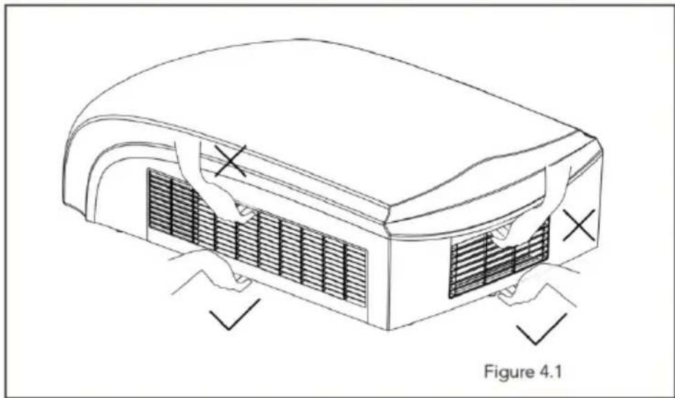
- Open the package and take out the outdoor unit. When taking out the outdoor unit after unpacking, do not lift the inlet and outlet grates. (see Figure4-1).
text_image
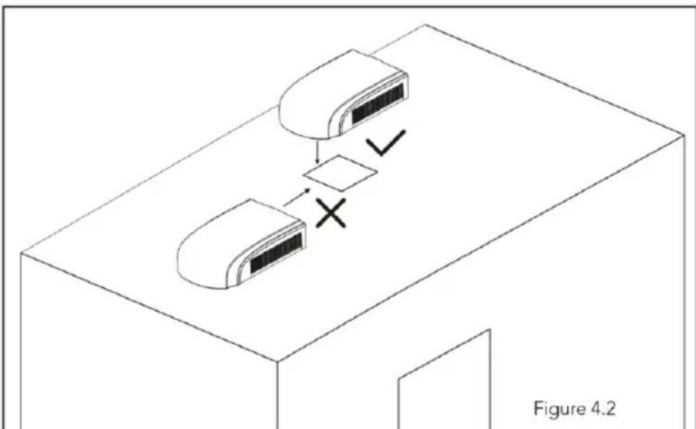
Figure 4.1- Installing the outdoor unit on the mounting adapter:
- Lift the outdoor unit. It is strictly forbidden to lift the air conditioner by the outer frame.
Put it on the mounting adapter on the prepared opening and make sure the sealing strip of the outdoor unit matches with the groove on the surface of the mounting plate.
Do not drag the outdoor unit, otherwise the seal may come off.
flowchart
graph TD
    A["Device 1"] --> B{Decision}
    B -->|Yes| C["Device 2"]
    B -->|No| D["Checkmark"]
    C --> E["Figure 4.2"]
STEP 4-INSTALLING THE CEILING ASSEMBLY
NOTICE
Make sure that the air conditioner and in and exterior ceiling fit properly together. Before tightening the bolts, check the following:
- The applicable thickness of the vehicle roof is 30mm to 80mm.
- Before tightening the bolts, hand tight the four bolts and prohibit the use of force.
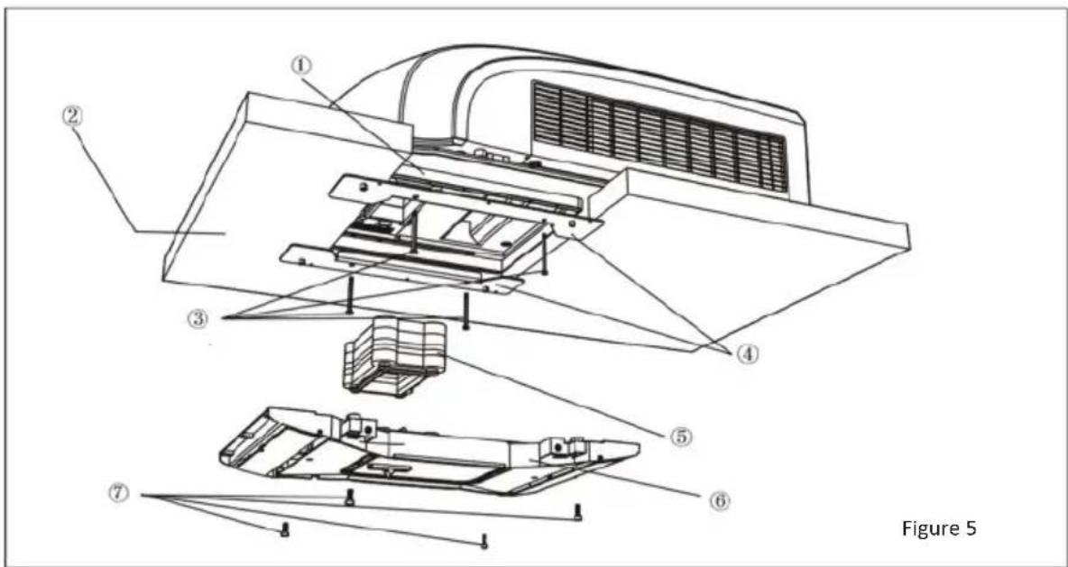
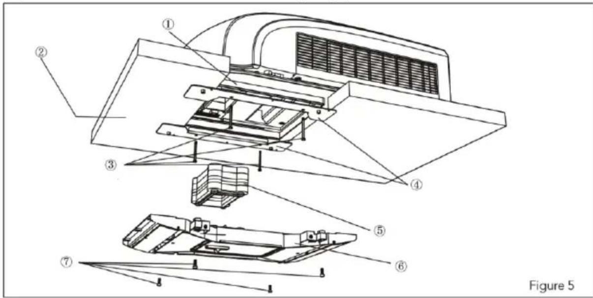
- The mounting brackets should overlap with the surface of the vehicle ceiling. Tighten the bolts in a cross pattern and make sure the screw holes align with the holes in the adapter. Maximum torque on the bolts (4) is 1,8Nm. (See figure 5)
text_image
Figure 51) Plastic adapter
2) Thickness of vehicle roof is 30mm - 80mm
3) 4 bolts (maximum torque is 1,8Nm)
4) Bracket
5) Air ducts
6) Ducting frame
7) 4 bolts
The following step by step instructions must be performed in the following sequence to ensure proper installation.
-
Carefully take the ceiling assembly out of the box.
-
Remove the ceiling grille from the ceiling assembly.
-
Carry the outdoor unit to the vehicle's top and align with the openings on the vehicle's top. Use 2 sets of mounting plate assembly and 4 screw bolts to mount the outdoor unit (See fig. 5).
-
You must start mounting the bolts by hand to avoid cross-threading. DO NOT START MOUNTING THE BOLTS WITH AN ELECTRIC TOOL OR AIR-GUN!
The mounting bolts should be tightened in a cross pattern, the process is completed when the base pan gasket is evenly compressed.
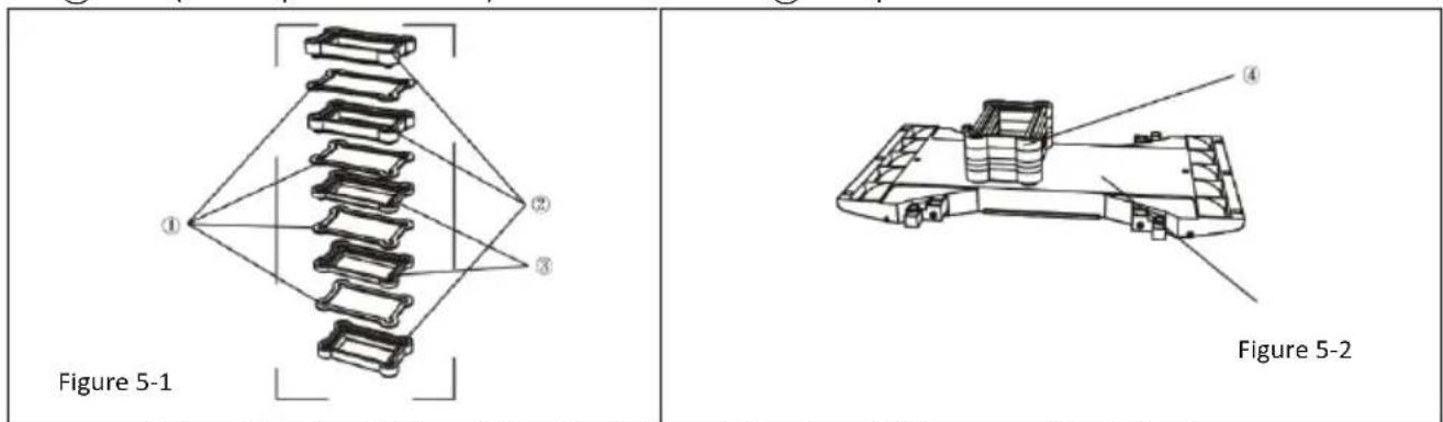
- Before installing the air duct assembly of the indoor unit, assemble the foam assembly according to the thickness of the vehicle's roof. Use an appropriate amount of Styrofoam and soft foam assembly.
Note: The foam shouldn't be more than 1 or 2 mm thicker than the roof thickness.
Stick the Styrofoam assembly with double faced adhesive tape (prepared by user) (See fig.5-1, 5-2).
- Install the foam assembly on the air duct assembly. Use 4 screw bolts to fix the air duct assembly onto the mounting plate. After connecting the outdoor unit with indoor unit, check whether the foam assembly has come loose (See fig.5).
text_image
Figure 5① plastic adapter
② Thickness of vehicle roof is from 30mm-80mm
③ 4 bolt (Max torque is from 1.8Nm)
④ bracket
⑤ wind duct frame
⑥ wind-path
⑦ 4 bolt
text_image
Figure 5-1 Figure 5-2① foam(4mm)
② foam(20mm)
③ foam(10mm)
④ foam
⑤ wind-path
ELECTRICAL WIRING
STEP 5-ELECTRICAL WIRING
ROUTING 220-240V AC WIRING
WARNING : Make sure that all power supply to the unit is disconnected before performing any work on the unit to avoid the possibility of shock or injury and/or damage to the equipment. After the interior ceiling assembly frame is properly secured to the roof top air conditioner, the following electrical connections must be performed.
-
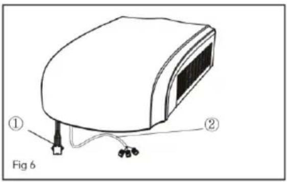
As shown in fig.6, the outdoor unit has two sets of outgoing wires, which are power cord (high current) and the control signal wires respectively. The former one should be directly connected to the power supply terminal while the latter one should be connected to the control signal wire of the indoor unit.
-
As shown in fig.7, the indoor unit has one set of control signal wires, with 1 wiring terminals in total.
-
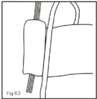
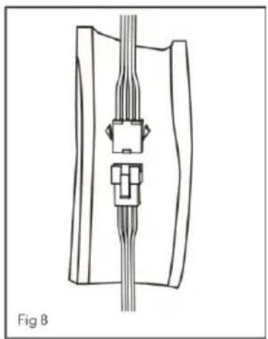
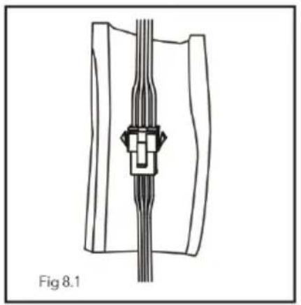
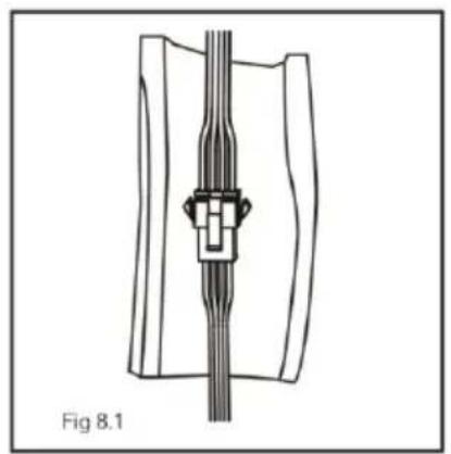
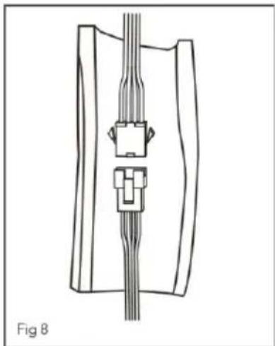
As shown in fig.8, connect the wiring terminals of indoor and outdoor units. Then use a piece of foam to wrap the wiring terminals together, with each terminal separately encircled by the sponge. Avoid gaps between each wire.
-
As shown in fig.9, Connect the external power cord to the cable reserved on the RV.
text_image
① Fig 6 ②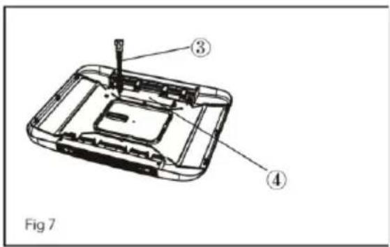
text_image
Fig 71) Outdoor connection wire 2) Outdoor electrical wire 3) Indoor electrical wire 4) Display board
natural_image
Technical line drawing of a mechanical assembly with no visible text or symbols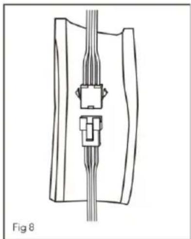
natural_image
Technical line drawing of a mechanical component with no visible text or symbolsUse a piece of thermal insulating jacket as shown in figure 8 to enclose the wiring terminals. Cover the insulated jacket with foam and fasten it with cable ties.
natural_image
Technical line drawing of a mechanical component with no visible text or symbols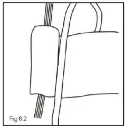
natural_image
Simple line drawing of a mechanical component with no text or symbols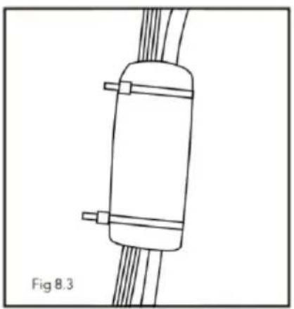
natural_image
Simple line drawing of a cylindrical object with two side connectors and connecting wires, labeled Fig 8.3 (no text or symbols on the object itself)NOTE
- Cable ties must be attached to the area with both sponge and thermal insulating jacket;
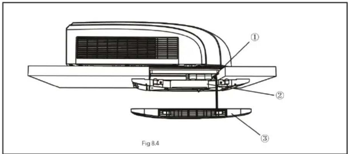
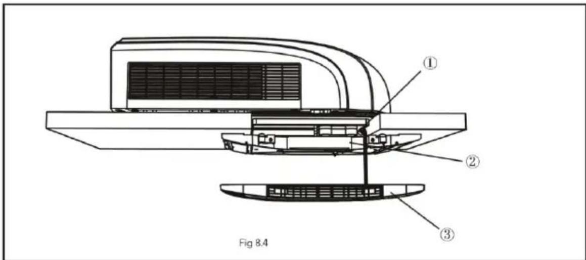
- Before installing the front panel of indoor unit, put the thermal insulating jacket on top of the air duct.
text_image
Fig 8.41) Insulation plates
2) Air duct
3) Inner panel
COMPLETING THE INSTALLATION
STEP 6-COMPLETING THE INSTALLATION
To complete the installation and system checkout requirements, the following steps must be performed.
- Secure the ceiling grille to the ceiling assembly wind-path with 4 screws. (see Figure 9).
- Install the air filter and air intake grill.
- Switch on the power supply and check functionality of the unit.
- Once the indoor unit is assembled, if the gap between the panel and the top of vehicle is not even, please ask the manufacturer to adjust it according to the assembly status.
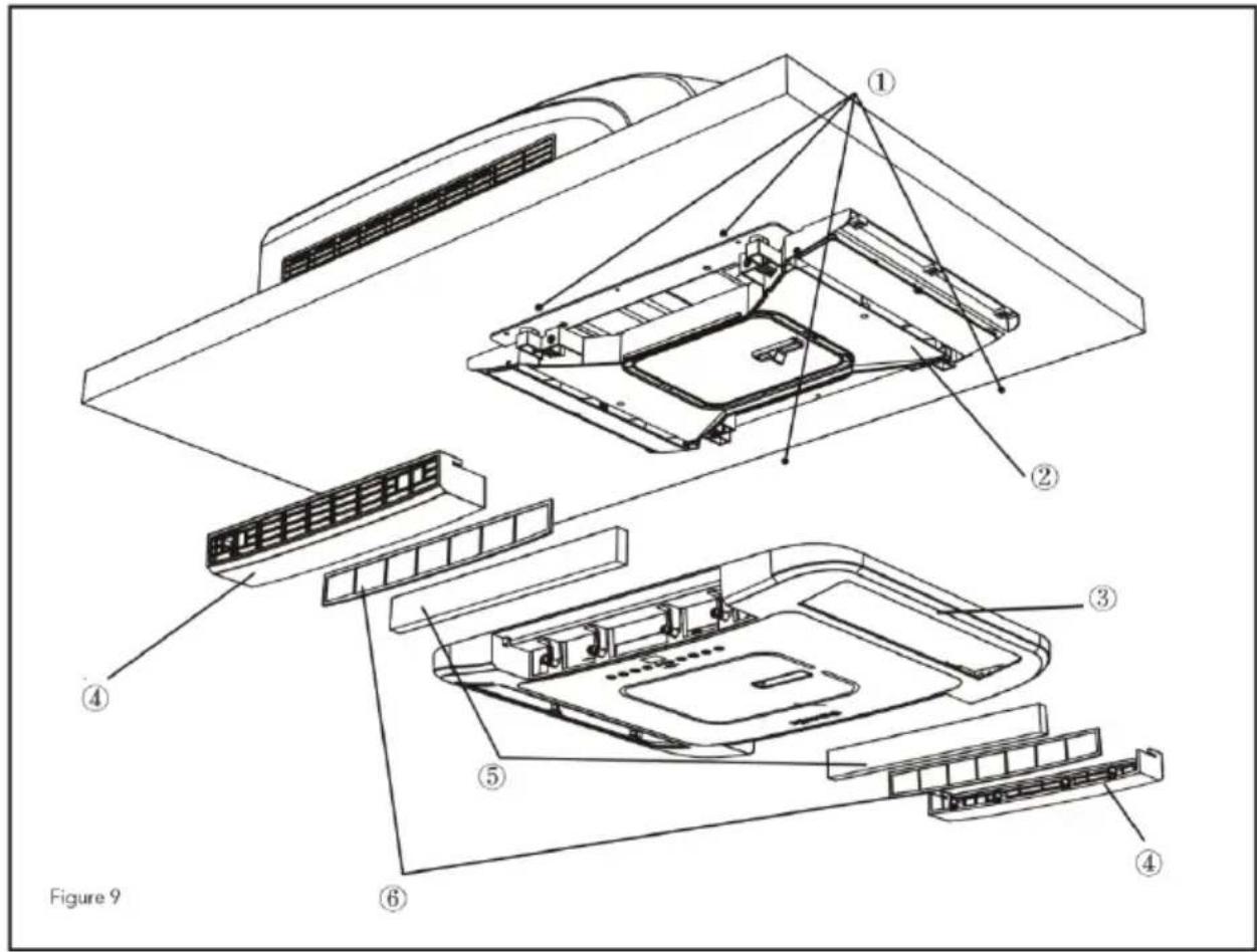
text_image
Figure 91) 4 screws
2) Air ducting frame
3) Inner panel
4) Air inlet grill
5) HEPA filter
6) Mesh
DISASSEMBLY
When installing the inner shell, pay attention to fasten the front and back fasteners, as shown in the figure by pressing the inner shell 1,2,3,4,5,6.
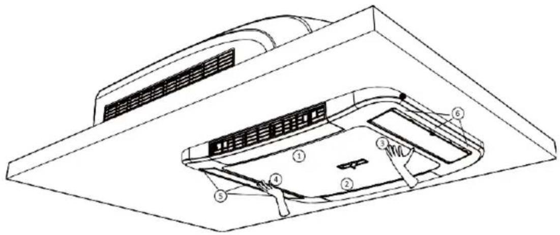
text_image
Technical diagram of a vehicle air duct system with numbered components for identificationWhen removing the inner shell, use a screwdriver to carefully pry open positions 3 and 4, and pull the inner shell down to remove the inner shell.
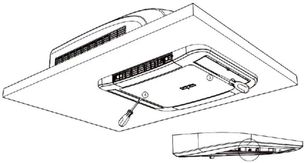
text_image
Technical diagram of a solar panel installation with labeled components and exploded viewEnlarged diagram of position 3 and 4
TROUBLESHOOTING
TROUBLESHOOTING GUIDE
If you have problems with your recreational vehicle air conditioner, check this guide before contacting your service representative.
| PROBLEM | POSSIBLE CAUSE | SOLUTION |
| The unit cannot start | The unit may not be connected to the power supply correctly. | Check the power supply of the vehicle and make sure it is provided correctly. |
| The unit cannot cool the room | The roof top air conditioner is not level. | Mount the roof top air conditioner as level as possible from front to rear and side to side when the vehicle is parked. Make sure that the mounting of the air conditioner is correct and level. |
| The temperature setting is too high. | Reset the remote control to a lower temperature setting. | |
| The air filter is dirty. | Remove and clean the filter. | |
| The room was already very hot before the unit was turned on. | Allow a sufficient amount of time for the unit to cool the room. | |
| The unit is making noise | The unit is click and gurgle. | These noise are normal during the operation of the unit. |
| The unit has water dripping inside | The base pan gasket had not been evenly compressed. | Mounting bolts should be tightened evenly by compressing the base pan gasket. |
| The unit has ice or frost on the coils | The temperature is low inside. | Select FAN mode at HIGH fan speed. |
| The filter is dirty. | Remove and clean the filter. |
ERROR CODES
When air conditioner status is abnormal, temperature indicator on indoor unit will blink to display corresponding error
code. Please refer to below list for identification of error code.
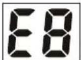
____ Indoor display
Indicator diagram is only for reference. Please refer to actual product for the actual indicator and position.
| ERROR CODE | TROUBLESHOOTING | |
| PL | The power supply voltage is too low. Please check whether the voltage is correct. It can be eliminated after restarting the unit. If not, please contact qualified professionals for service. | |
| E1/E2/E3/E4/EC | Please contact qualified professionals for service. | |
| EE | Something is blocking the air intake grill of indoor unit and causing an abnormal airflow to the indoor unit | Please check if there is something blocking the air intake grill and remove it. |
| HEPA filter is too dirty and causing an abnormal airflow | Please replace the HEPA filter with a new one | |
| When the unit is in cooling mode, the ambient working temperature is too low | Using remote control or app to enter fan mode | |
| Use the cooling mode when the ambient temperature is higher | ||
Note: If there're other error codes, please contact qualified professionals for service.
REGUALR MAINTENANCE PROCEDURES
| ACTIVETY | FREQUENCY |
| Clean the filter and HEPA(More frequent cleaning may be necessary depending on the air quality) | It is recommended to replace the HEPA after one year of use. |
HOW TO REMOVE THE AIR FILTER
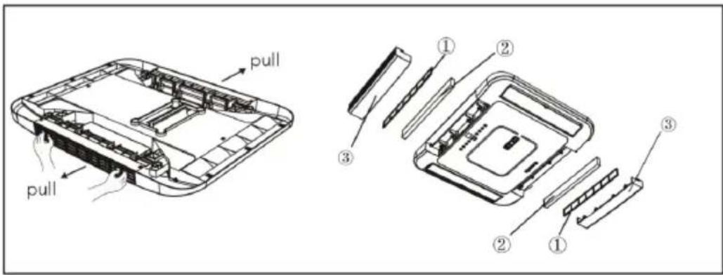
Pull the air inlet grille out by hand in the direction of the arrow and remove the mesh and HEPA-filter.
text_image
pull pull ① ② ③ ② ① ③① Mesh
② HEPA-filter
③ Air-inlet grille
HOW TO CLEAN THE AIR MESH AND HEPA-FILTER
Wash away dust from the air filters with clean water or vacuum the filter with an electric household vacuum cleaner.
Clean the HEPA with a household electric vacuum cleaner. If you find that the HEPA is dirty and cannot be used after cleaning, you need to find the manufacturer to buy a new HEPA-filter for replacement.
WARNING
FAILURE TO FOLLOWING INSTRUCTIONS COULD RESULT IN SERIOUS PERSONAL INJURY
- Don't touch the capacitor terminals without the electric discharge, the capacitor still may have the high voltage even though the power supply is turned off.
- Be careful when you maintain the refrigeration system, which has the high internal pressure.
- Do not block the filter and the indoor air inlet badly to prevent water leakage.

RECYCLING
This product bears the selective sorting symbol for waste electrical and electronic equipment. This means that this product must be handled pursuant to European Directive (2012/19/EU) in order to be recycled or dismantled to minimize its impact on the environment. For further information, please contact your local or regional authorities. Electronic products not included in the selective sorting process are potentially dangerous for the environment and human heath due to the presence of
hazardous substances.
DECLARATION OF CONFORMITY
Hereby Gimeg Nederland B.V. declares that the device RTA-2500L, applies all basic requirements and other relevant regulations listed in the European directive for radio equipment (2014/53/EU), electromagnetic compatibility (2014/30/EU) and low voltage directive (2014/35/EU). If you require a full declaration of conformity, you can contact the address listed on the backside of this manual.
text_image
Technical diagram of a device with numbered components and an external control panel labeled 'g/mestic'.⑨
text_image
Technical diagram of a device with numbered components, showing front and side views with labeled parts.text_image
Operation mode * - 88-88 88-88 88-88 9-1 9-10text_image
QR code image containing encoded data, no visible human-readable textnatural_image
Technical line drawing of a device casing with internal components and labeled section (1), no readable text or symbols beyond labeltext_image
Figure 1-2PRECAUCIÓN
text_image
Figure 4.1text_image
Figure 4.2text_image
Technical diagram of a refrigerator internal structure with numbered components for identificationFigura 5
text_image
① Fig 6 ②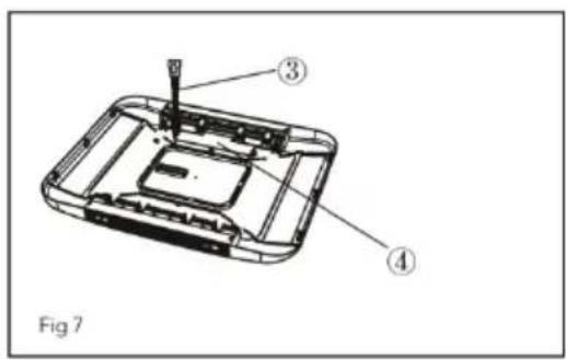
text_image
Fig 7 ③ ④natural_image
Technical line drawing of a mechanical assembly with no visible text or symbols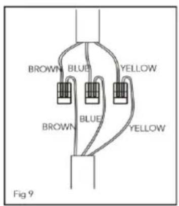
text_image
BROWN BLUE YELLOW BROWN BLUE YELLOW Fig 9natural_image
Technical line drawing of a mechanical component with no visible text or symbols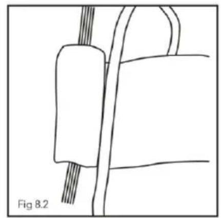
natural_image
Simple line drawing of a mechanical component with wires, labeled Fig 8.2 (no text or symbols on the diagram itself)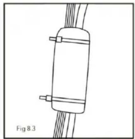
natural_image
Simple line drawing of a cylindrical object with two protruding pins, connected to wires (no text or symbols)NOTE
text_image
Technical diagram of a car air duct system with numbered components for identificationnatural_image
Technical line drawing of a device interior with labeled components (no text or symbols present)text_image
pull pull ① ② ③ ② ①① Malla
② Filtro HEPA
③ Rejilla de entrada de aire
CÓMO LIMPIAR LA MALLA DE AIRE Y EL FILTRO HEPA
text_image
Technical diagram of a device with numbered components and a digital display showing 88% power.text_image
Technical diagram of a device with numbered components, showing front and side views with labeled parts.text_image
Operation mode 0-1 0-0text_image
QR code image containing encoded data, no visible human-readable textINSTRUCTIONS D'INSTALLATION
AVANT L'INSTALLATION
natural_image
Technical line drawing of a device casing with internal components and labeled part (1), no readable text or symbols beyond labeltext_image
Standard Dimension Figure 1-2ATTENTION
text_image
Figure 4.1natural_image
Technical line drawing of a mechanical assembly with no visible text or symbolsFigure 5-2
① mousse (4 mm) ② mousse (20 mm) ③ mousse (10 mm) ④ mousse ⑤ chemin de vent
CÂBLAGE ÉLECTRIQUE
ÉTAPE 5 - CÂBLAGE ÉLECTRIQUE
ROUTAGE DU CÂBLAGE 220-240 V AC
text_image
① Fig 6 ②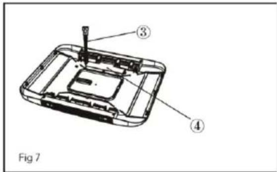
text_image
Fig 7 ③ ④natural_image
Technical line drawing of a mechanical assembly with no visible text or symbols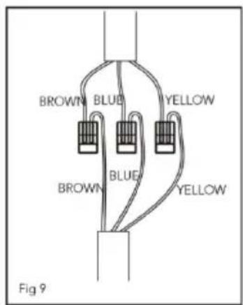
text_image
BROWN BLUE YELLOW BROWN BLUE YELLOW Fig 9natural_image
Technical line drawing of a mechanical component with no visible text or symbols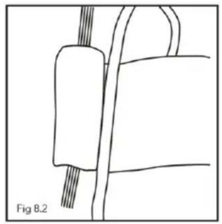
natural_image
Simple line drawing of a mechanical component with wires, labeled Fig 8.2 (no text or symbols on the diagram itself)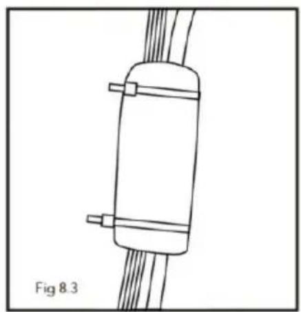
natural_image
Simple line drawing of a cylindrical object with two side connectors and connecting wires, labeled Fig 8.3 (no text or symbols on the object itself)NOTE
text_image
Technical diagram of a vehicle air duct system with numbered components for identificationtext_image
Technical diagram of a car air conditioner unit with labeled components and exploded viewtext_image
pull pull ① ② ③ ② ①DÉCLARATION DE CONFORMITÉ
Roof Top Air Conditioner
flowchart
graph TD
    A["OUTDOOR TUBE SENSOR"] --> B["OPT"]
    C["TUBE SENSOR"] --> D["PT T-SEN"]
    E["ROOM SENSOR"] --> F["RT"]
    G["4-WAY VALVE"] --> H["VT BU"]
    I["4-WAY VALVE"] --> J["VT BU"]
    K["CAP."] --> L["C1"]
    M["M1"] --> N["IN_FAN MOTOR"]
    O["PE"] --> P["FAN"]
    Q["LND"] --> R["BN BU"]
    S["NYEGN POWER PE"] --> T["ACN1 ACN2"]
    U["RD"] --> V["CAP. BK"]
    W["RD"] --> X["C2"]
    Y["YEGN PE"] --> Z["COMP. COMP."]
    AA["K1 COMP"] --> AB["BU"]
    AC["OPFAN"] --> AD["ON"]
    AE["OFAN_C"] --> AF["ON"]
    AG["M2 OUT_FAN MOTOR"] --> AH["PE"]
    AI["OUTDOOR TUBE SENSOR"] --> AJ["(RD)"]
    AK["TUBE SENSOR"] --> AL["(YE)"]
    AM["ROOM SENSOR"] --> AN["RT"]
    AO["4-WAY VALVE"] --> AP["VT BU"]
    AQ["4-WAY VALVE"] --> AR["VT BU"]
    AS["EN_FAN MOTOR"] --> AT["WH YE BU BK PE"]
    AU["OPEN MODE"] --> AV["DISP"]
    AW["MAIN BOARD"] --> AX["PE"]
    AY["INDOOR UNIT"] --> AZ["LND"]
LISTA D'IMBALLAGGIO
 1 1 |  2 2 | 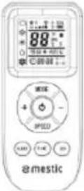 3 3 |  4 4 |
 5 5 |  6 6 |  7 7 |  8 8 |
 9 9 |  10 10 | 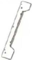 11 11 | 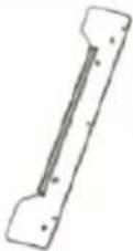 12 12 |
 13 13 |  14 14 | 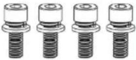 15 15 | 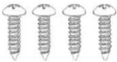 16 16 |
text_image
Technical diagram of a device with numbered components and a digital display showing 88% power.text_image
Diagram of a device with labeled parts, showing internal structure and numbered annotations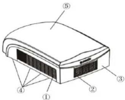
text_image
Diagram of a device with numbered parts labeled ① to ⑤, likely illustrating a component or layout.text_image
QR code image containing encoded data, no visible human-readable textnatural_image
Technical line drawing of a mobile phone casing with internal components and labeled part (1), no readable text or symbols beyond labeltext_image
Figure 1-2ATTENZIONE
text_image
Figure 4.1text_image
Figure 4.2STEP 4 – INSTALLAZIONE DEL GRUPPO CONTROSOFFITTO
AVVISO
text_image
Technical diagram of a device with numbered components, showing internal structure and assembly stepstext_image
Figura 5-1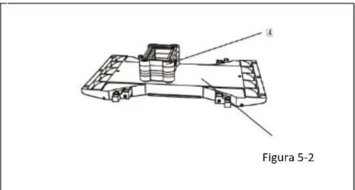
text_image
Figura 5-2text_image
① Fig 6 ②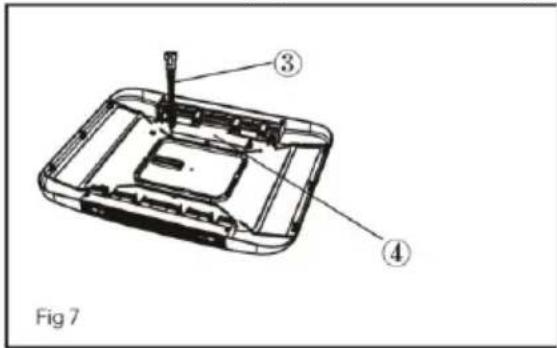
text_image
Fig 7natural_image
Technical line drawing of a mechanical component with no visible text or symbols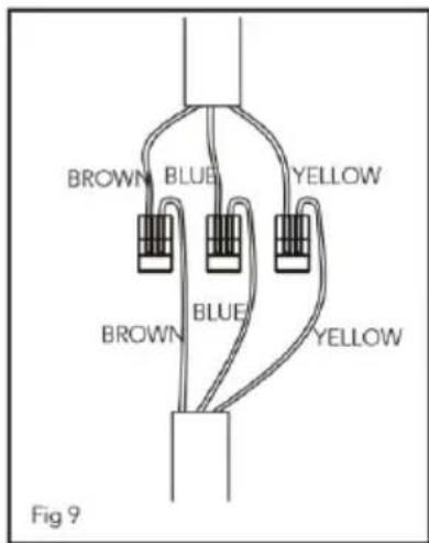
text_image
BROWN BLUE YELLOW BROWN BLUE YELLOW Fig 9natural_image
Technical line drawing of a mechanical component with no visible text or symbols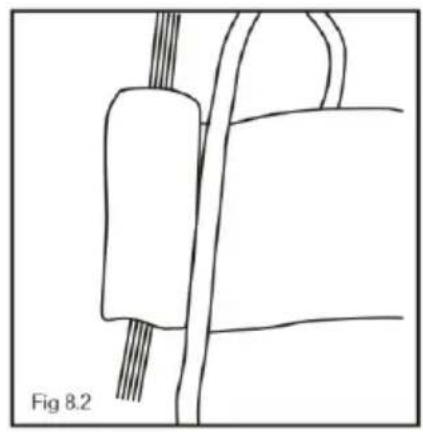
natural_image
Simple line drawing of a mechanical component with no text or symbols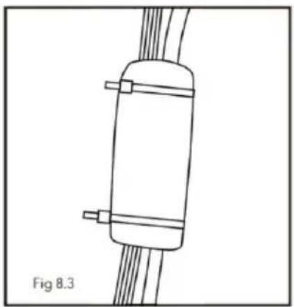
natural_image
Simple line drawing of a cylindrical object with two connectors and coiled wires, labeled Fig 8.3 (no text or symbols on the object itself)NOTE
text_image
① ② ③ Fig 8.4text_image
Technical diagram of a car air duct system with numbered components for identificationtext_image
Technical diagram of a car air conditioner unit with labeled components and exploded viewtext_image
pull pull ① ② ③ ② ①NOEN ORD OM DITT NYE KLIMAANLEGG
text_image
Technical diagram of a device with numbered components and a digital display showing temperature reading.① Luft ut-gitter ② Luft inn-gitter ③ Kontrollpanel (membran) ④ Filterunderenhet ⑤ LED-indikator
⑥ Betjeningshåndtak ⑦ Fjernmottakervindu ⑧ Innstillingstemperatur ⑨ Fjernkontroll
Outdoor Unit
text_image
Diagram of a device with labeled parts, showing internal structure and numbered annotations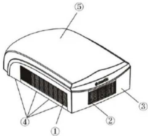
text_image
Diagram of a device with numbered parts labeled 1 through 5, showing internal structure and connections.① Luft inn-gitter ② Luft-ut-gitter ③ Ramme ④ Dreneringsuttak ⑤ Ytre innfatning
Merknad:
text_image
QR code image containing encoded data, no visible human-readable textnatural_image
Technical line drawing of a device rear panel with internal components and a pointer indicating a component (no text or symbols present)text_image
Figure 1-2FORSIKTIGHET
text_image
Figure 4.1text_image
Technical diagram of a device with numbered components, showing internal structure and assembly stepstext_image
Figur 5-1 Figur 5-2① skum (4 mm)
② skum (20 mm)
③ skum (10 mm)
④ skum
⑤ vindbane
ELEKTRISK KABLING
TRINN 5 - ELEKTRISK KABLING
RUTE 220-240 V AC KABLING
natural_image
Technical line drawing of a mechanical component with no visible text or symbols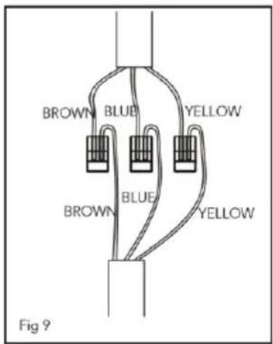
text_image
BROWN BLUE YELLOW BROWN BLUE YELLOW Fig 9text_image
① Fig 6 ②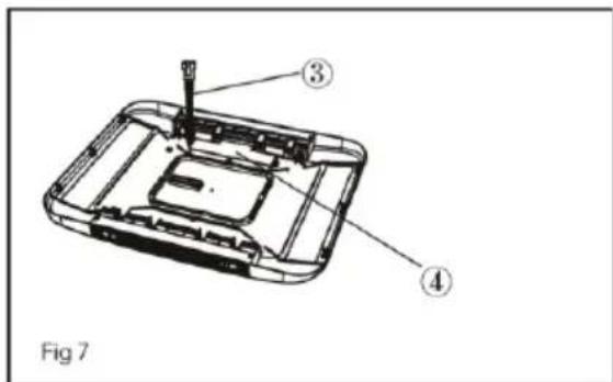
text_image
Fig 7Bruk et stykke termisk isolerende hylse som vist i figur 8 for å omslutte ledningsterminalene. Dekk den isolerte kappen med skum og fest den med kabelbånd.
natural_image
Technical line drawing of a mechanical component with no visible text or symbols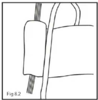
natural_image
Simple line drawing of a mechanical component with wires, labeled Fig 8.2 (no text or symbols on the diagram itself)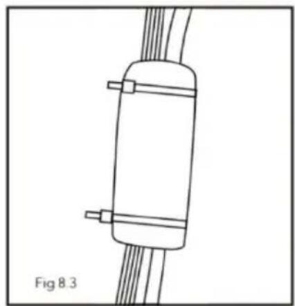
natural_image
Simple line drawing of a cylindrical object with two side connectors and connecting wires, labeled Fig 8.3 (no text or symbols on the object itself)NOTE
- Kabelbindere må festes til området med både skum og den varmeisolerende kappen.
- Før du installerer panelet til innendørsenheten, sett den varmeisolerende kappen på toppen av luftkanalen.
text_image
Fig 8.41) Isolasjonsplate
2) Luftkanaldel
3) Frontpanel
FULLF∅RE INSTALLASJONEN
TRINN 6 - FULLF∅RE INSTALLASJONEN
text_image
Technical diagram of a car air duct system with numbered components for identificationtext_image
Technical diagram of a ventilation system with labeled components and internal structureVANLIGE VEDLIKEHOLDSPROSEDYRER
text_image
pull pull ① ② ③ ② ①① Nett
② HEPA-filter
③ Luftinntaksrist
SLIK RENGJ∅R DU LUFTNETTET OG HEPA-FILTERET
Vask bort støv fra luftfiltrene med rent vann eller støvsug filteret med en elektrisk husholdningsstøvsuger.
Roof Top Air Conditioner
flowchart
graph TD
    A["OUTDOOR TUBE SENSOR"] --> B["(WH)"]
    C["TUBE SENSOR"] --> D["(RD)"]
    E["ROOM SENSOR"] --> F["(YE)"]
    G["4-WAY VALVE"] --> H["VT BU"]
    I["4YV"] --> J["VT BU"]
    K["CAP."] --> L["C1"]
    M["IN_FAN MOTOR"] --> N["M1"]
    O["PE"] --> P["FAN"]
    Q["LNDOR UNIT"] --> R["INDOOR"]
    S["L N"] --> T["POWER"]
    U["L"] --> V["BN BU"]
    W["YEGN"] --> X["ACN1 ACN2"]
    Y["DISP"] --> Z["ACL"]
    AA["K1 COMP"] --> AB["COMP"]
    AC["OPT"] --> AD["ACN1"]
    AE["ACN2"] --> AF["ACN1"]
    AG["RD"] --> AH["CAP. BK"]
    AI["RD"] --> AJ["C2"]
    AK["YEGN"] --> AL["COMP"]
    AM["PE"] --> AN["COMP."]
    AO["OUT_FAN MOTOR"] --> AP["M2"]
    AQ["PE"] --> AR["OUT_FAN MOTOR"]
PACKLISTA
 1 1 | 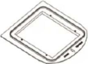 2 2 |  3 3 | 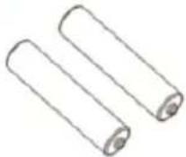 4 4 |
 5 5 | 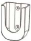 6 6 | 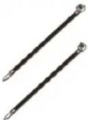 7 7 |  8 8 |
 9 9 |  10 10 |  11 11 | 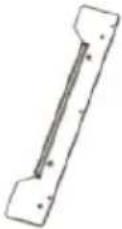 12 12 |
 13 13 |  14 14 | 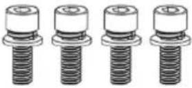 15 15 | 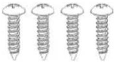 16 16 |
text_image
Diagram of a digital device with numbered components and a control panel labeled 'mestic' in Chinese.① Luftutloppsgaller ② Luftinloppsgaller ③ Kontrollpanel (membran) ④ Filter underenhet ⑤ LED-indikator
text_image
Technical diagram of a device with numbered components, showing front and side views with labeled parts.① Luftinloppsgaller ② Luftutloppsgaller ③ Ram ④ Dräneringsutlopp ⑤ Yttre hölje
Obs:
text_image
QR code image containing encoded data, no visible human-readable textINSTALLATIONSINSTRUKTIONER
INNAN INSTALLATION
natural_image
Technical line drawing of a device casing with internal components and a numbered label (1), no readable text or symbols present.text_image
Figure 1-2WARNING
text_image
Technical diagram of an air conditioner unit with 5° and 0° angle annotationstext_image
400 mm/390 400 mm/390text_image
Figure 4.1natural_image
Technical line drawing of a mechanical assembly with no visible text or symbolsFigur 5-2
① skum (4 mm)
② skum (20 mm)
③ skum (10 mm)
④ skum
⑤ vindbana
ELEKTRISKA KABLAR
STEG 5-ELEKTRISKA KABLAR
DRAGNING 220-240V AC-KABLAGE
text_image
① Fig 6 ②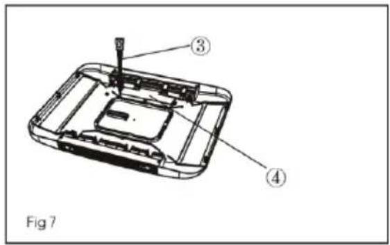
text_image
Fig 71) Utomhusanslutningskabel 2) Utomhuselkabel 3) Inomhuselkabel 4) Displaytavla
natural_image
Technical line drawing of a mechanical component with no visible text or symbols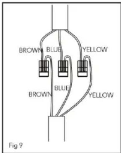
text_image
BROWN BLUE YELLOW BROWN BLUE YELLOW Fig 9natural_image
Technical line drawing of a mechanical component with no visible text or symbols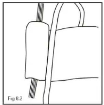
natural_image
Simple line drawing of a mechanical component with no text or symbols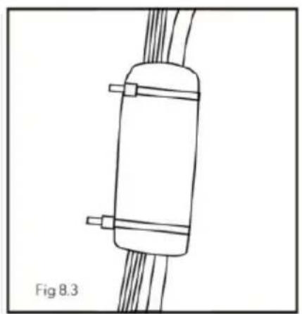
natural_image
Simple line drawing of a cylindrical device with two connectors and coiled wires, labeled Fig 8.3 (no text or symbols on the diagram itself)NOTE
SLUTFÖRA INSTALLATIONEN
STEG 6 - SLUTFÖRA INSTALLATIONEN
text_image
Technical diagram of a vehicle air duct system with numbered components for identificationnatural_image
Technical line drawing of a car air conditioner unit with labeled components (no text or symbols present)text_image
pull pull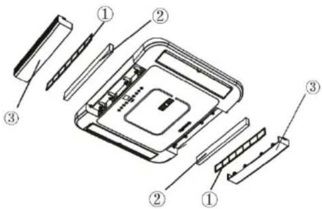
text_image
Exploded view diagram of a computer with numbered parts for identification
② HEPA-filter
③ Luftintagsgaller