
PTBMOD 710 D1 - Drill PARKSIDE - Free user manual and instructions
Find the device manual for free PTBMOD 710 D1 PARKSIDE in PDF.


| Product type | Column drill with electronic speed control |
| Brand | Parkside |
| Model | PTBMOD 710 D1 |
| Supply voltage | 230-240 V~ 50 Hz |
| Rated power (S1) | 710 W |
| Maximum power (S6 10%) | 900 W |
| Speed range | 500 – 2600 min⁻¹ |
| Chuck type | B16 (1.5 – 13 mm) |
| Max drilling capacity (steel) | 13 mm |
| Max drilling capacity (wood) | 40 mm |
| Drilling stroke | 70 mm |
| Distance chuck to base | 280 mm |
| Weight | 7.6 kg |
| Protection class | II |
| IP rating | IPX0 |
| Laser | Class II, 650 nm, < 1 mW |
| Electronic speed control | Yes, continuous |
| Depth stop | Yes, with scale |
| Parallel guide | Yes |
| Cross laser | Yes, for centering |
| Sound pressure level | 80.1 dB(A) |
| Sound power level | 93.1 dB(A) |
| Vibration (hand-arm) | ≤ 2.5 m/s² |
| Maintenance | Regular cleaning, no special maintenance |
| Spare parts available | Yes (chuck, key, guide, etc.) |
| Warranty | 3 years |
Frequently Asked Questions - PTBMOD 710 D1 PARKSIDE
User questions about PTBMOD 710 D1 PARKSIDE
0 question about this device. Answer the ones you know or ask your own.
Ask a new question about this device
Download the instructions for your Drill in PDF format for free! Find your manual PTBMOD 710 D1 - PARKSIDE and take your electronic device back in hand. On this page are published all the documents necessary for the use of your device. PTBMOD 710 D1 by PARKSIDE.
USER MANUAL PTBMOD 710 D1 PARKSIDE
natural_image
Technical line drawing of a mechanical drill press with a base mount (no text or symbols)
BENCH PILLAR DRILL WITH ELECTRONIC SPEED CONTROL PTBMOD 710 D1 TISCHBOHRMASCHINE MIT ELEKTRONISCHER DREHZAHLREGELUNG PTBMOD 710 D1 PERCEUSE À COLONNE AVEC RÉGLAGE ÉLECTRONIQUE PTBMOD 710 D1

Bench Pillar Drill with Electronic Speed Control Operating and Safety Instructions
Translation of the original operating instructions

Before reading, unfold the page with the illustrations and then familiarise yourself with all the functions of the product.
DE AT CH
GB / IE / NI / CY / MT Operating and Safety Instructions Page 1
1 Explanation of the symbols on the product.... 2
2 Introduction.... 3
3 Product description (Fig. 1-10) 3
4 Scope of delivery (Fig. 2).... 3
5 Proper use.... 3
6 Safety instructions 4
7 Technical data.... 6
8 Unpacking.... 7
9 Installation (Fig. 1, 2)....7
10 Before commissioning 8
11 Operation 10
12 Working instructions 10
13 Cleaning and maintenance 11
14 Electrical connection.... 11
15 Transport (Fig. 1).... 12
16 Storage.... 12
17 Repair and ordering spare parts 12
18 Disposal and recycling.... 13
19 Troubleshooting.... 13
20 EU Declaration of Conformity 14
21 Warranty certificate.... 15
22 Exploded view.... 184
1 Explanation of the symbols on the product
Symbols are used in this manual to draw your attention to potential hazards. The safety symbols and the accompanying explanations must be fully understood. The warnings themselves will not rectify a hazard and cannot replace proper accident prevention measures.
 | Before commissioning, read and observe the operating manual and safety instructions! |
 | Attention! Failure to observe the safety signs and warning information affixed to the product and failure to observe the safety and operating manual can result in serious injury or ev death. |
 | Wear safety goggles. |
 | Wear hearing protection. |
 | Wear a hair net! |
 | Do not wear gloves during operation! |
 | Attention! Keep your hands away from rotating tools. |
 | Attention! Laser beam |
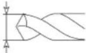 | Drill diameter |
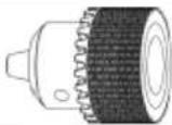 | Chuck adapter |
 | Only carry out maintenance, conversion, adjustment and cleaning work when the product is switched off and the mains plug is disconnected! |
 | The product complies with the applicable European directives. |
2 Introduction
Manufacturer:
Scheppach GmbH
Günzburger Straße 69
D-89335 Ichenhausen
Dear Customer
We hope your new product brings you much enjoyment and success.
Note:
In accordance with the applicable product liability laws, the manufacturer of this product assumes no liability for damage to the product or caused by the product arising from:
- Improper handling
• Non-compliance with the operating manual
• Repairs carried out by third parties, unauthorised specialists - Installing and replacing non-original spare parts
- Improper use
- Failures of the electrical system in the event of the electrical regulations and VDE provisions 0100, DIN 57113 / VDE0113 not being observed.
Note:
The operating manual is part of this product.
It includes important instructions for the safe, proper and economic operation of the product, for avoiding danger, for minimising repair costs and downtimes and for increasing the reliability and extending the service life of the product. In addition to the safety instructions in this operating manual, you must also observe the regulations applicable to the operation of the product in your country.
Familiarise yourself with all operating and safety instructions before using the product. Only operate the product as described and for the specified areas of application. Keep the operating manual in a good place and hand over all documents when passing the product on to third parties.
3 Product description (Fig. 1-10)
- Depth stop (with scale)
1a. Scale pointer
1b. Phillips screw - Handle
2a. Hand spindle guide
2b. Screw M6
2c. Nut M6
2d. Spacer - On/off switch
- Speed control
- Chuck
5a. Nut - Quick clamp
6a. Quick-clamp screw
7. Floor plate
7a. Grub screw (M6)
7b. Groove
8. Parallel stop
8a. Wing screws
9. Column tube
9a. Guiding pin
10. Toothed rack
11. Clamping lever (height adjustment)
12. Clamping lever (depth stop)
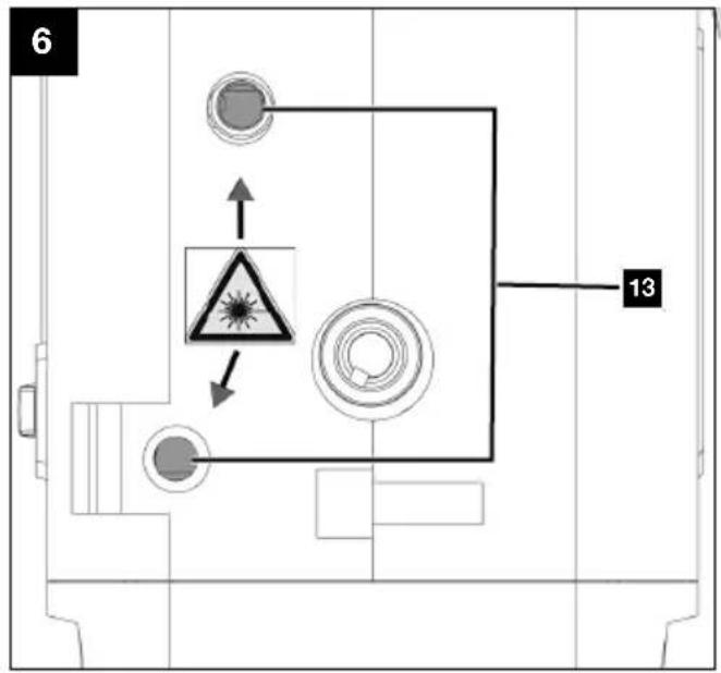
13. Laser cross
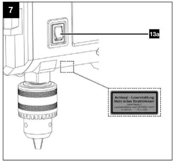
13a. On/off switch
14. Chuck key
14a. Chuck key holder
15. Allen key, 4 mm
4 Scope of delivery (Fig. 2)
Item Quantity Designation
- 1 x Depth stop (with scale)
2.1 x Handle
2d. 1 x Spacer
5.1 x Chuck - 1 x Quick clamp
7.1 x Floor plate - 1 x Parallel stop
-
1 x Column tube
-
1 x Clamping lever (depth stop)
-
1 x Chuck key
-
1 x Allen key, 4 mm
1 x Bench drill
1 x Operating manual
5 Proper use
The bench drill is designed for drilling in metal, wood, plastic and tiles. Shank drill bits from 1.5 mm to 13 mm drill diameter can be used.
The product may only be used in the intended manner. Any use beyond this is improper. The user, not the manufacturer, is responsible for damages or injuries of any type resulting from this.
An element of the intended use is also the observance of the safety instructions, as well as the assembly instructions and operating information in the operating manual.
Persons who operate and maintain the product must be familiar with the manual and must be informed about potential dangers.
The liability of the manufacturer and resulting damages are excluded in the event of modifications of the product.
The product may only be operated with original parts and original accessories from the manufacturer.
The safety, operating and maintenance specifications of the manufacturer, as well as the dimensions specified in the technical data, must be observed.
Please note that our products were not designed with the intention of use for commercial or industrial purposes. We assume no guarantee if the product is used in commercial or industrial applications, or for equivalent work.
Explanation of the signal words in the operating manual

DANGER
Signal word to indicate an imminently hazardous situation which, if not avoided, will result in death or serious injury.

WARNING
Signal word to indicate a potentially hazardous situation which, if not avoided, could result in death or serious injury.

CAUTION
Signal word to indicate a potentially hazardous situation which, if not avoided, could result in minor or moderate injury.
ATTENTION
Signal word to indicate a potentially hazardous situation which, if not avoided, could result in product or property damage.
6 Safety instructions
General power tool safety warnings

WARNING
Read all safety warnings, instructions, illustrations and specifications provided with this power tool.
Failure to follow all instructions listed below may result in electric shock, fire and/or serious injury.
Save all warnings and instructions for future reference.
The term “power tool” in the warnings refers to your mains-operated (corded) power tool or battery-operated (cordless) power tool.
1) Work area safety
a) Keep your work area clean and well-lit. Cluttered or dark areas invite accidents.
b) Do not operate power tools in explosive atmospheres, such as in the presence of flammable liquids, gases or dust. Power tools create sparks which may ignite the dust or fumes.
c) Keep children and bystanders away while operating a power tool. Distractions can cause you to lose control.
2) Electrical safety
a) Power tool plugs must match the outlet. Never modify the plug in any way. Do not use any adapter plugs with earthed (grounded) power tools. Unmodified plugs and matching outlets will reduce risk of electric shock.
b) Avoid body contact with earthed or grounded surfaces, such as pipes, radiators, ranges and refrigerators. There is an increased risk of electric shock if your body is earthed or grounded.
c) Do not expose power tools to rain or wet conditions. Water entering a power tool will increase the risk of electric shock.
d) Do not abuse the cord. Never use the cord for carrying, pulling or unplugging the power tool. Keep cord away from heat, oil, sharp edges or moving parts. Damaged or entangled cords increase the risk of electric shock.
e) When operating a power tool outdoors, use an extension cord suitable for outdoor use. Use of a cord suitable for outdoor use reduces the risk of electric shock.
f) If operating a power tool in a damp location is unavoidable, use a residual current device (RCD) protected supply. Use of an RCD reduces the risk of electric shock.
3) Personal safety
a) Stay alert, watch what you are doing and use common sense when operating a power tool. Do not use a power tool while you are tired or under the influence of drugs, alcohol or medication. A moment of inattention while operating power tools may result in serious personal injury.
b) Use personal protective equipment. Always wear eye protection. Protective equipment such as a dust mask, non-skid safety shoes, hard hat or hearing protection used for appropriate conditions will reduce personal injuries.
c) Prevent unintentional starting. Ensure the switch is in the off-position before connecting to power source and/or battery pack, picking up or carrying the tool. Carrying power tools with your finger on the switch or energising power tools that have the switch on invites accidents.
d) Remove any adjusting key or wrench before turning the power tool on. A wrench or a key left attached to a rotating part of the power tool may result in personal injury.
e) Do not overreach. Keep proper footing and balance at all times. This enables better control of the power tool in unexpected situations.
f) Dress properly. Do not wear loose clothing or jewellery. Keep your hair and clothing away from moving parts. Loose clothes, jewellery or long hair can be caught in moving parts.
g) If devices are provided for the connection of dust extraction and collection facilities, ensure these are connected and properly used. Use of dust collection can reduce dust-related hazards.
h) Do not let familiarity gained from frequent use of tools allow you to become complacent and ignore tool safety principles. A careless action can cause severe injury within a fraction of a second.
4) Power tool use and care
a) Do not force the power tool. Use the correct power tool for your application. The correct power tool will do the job better and safer at the rate for which it was designed.
b) Do not use the power tool if the switch does not turn it on and off. Any power tool that cannot be controlled with the switch is dangerous and must be repaired.
c) Disconnect the plug from the power source and/or remove the battery pack, if detachable, from the power tool before making any adjustments, changing accessories, or storing power tools. Such precautionary measures reduce the risk of starting the power tool accidentally.
d) Store idle power tools out of the reach of children and do not allow persons unfamiliar with the power tool or these instructions to operate the power tool. Power tools are dangerous in the hands of untrained users.
e) Maintain power tools and accessories. Check for misalignment or binding of moving parts, breakage of parts and any other condition that may affect the power tool's operation. If damaged, have the power tool repaired before use. Many accidents are caused by poorly maintained power tools.
f) Keep cutting tools sharp and clean. Properly maintained cutting tools with sharp cutting edges are less likely to bind and are easier to control.
g) Use the power tool, accessories and tool bits etc. in accordance with these instructions, taking into account the working conditions and the work to be performed. Use of the power tool for operations different from those intended could result in a hazardous situation.
h) Keep handles and grasping surfaces dry, clean and free from oil and grease. Slippery handles and grasping surfaces do not allow for safe handling and control of the tool in unexpected situations.
5) Service
a) Have your power tool serviced by a qualified repair person using only identical replacement parts. This will ensure that the safety of the power tool is maintained.
Safety instructions for transportable drills
a) The drill must be secured. An incorrectly secured drill can move or topple and this can result in injuries.
b) The workpiece must be clamped or fastened to the workpiece support. Do not drill into workpieces that are too small to be securely clamped. Holding the workpiece by hand can lead to injuries.
c) Do not wear gloves. Gloves can be caught by rotating parts or drilling debris and thus cause injuries.
d) Keep your hands away from the drilling area whilst the electrical tool is running. Contact with rotating parts or drilling debris can cause injuries.
e) The drill must be turning before it makes contact with the workpiece. Otherwise, the drill bit can catch in the workpiece and this can result in an unexpected movement of the workpiece and cause injuries.
f) If the drill becomes jammed, stop pressing downwards and switch the electrical tool off. Investigate and rectify the cause of the jamming. Jamming can result in an unexpected movement of the workpiece and can result in serious injuries.
g) Avoid long pieces of drill swarf by interrupting the downward pressure at regular intervals. Sharp metal swarf can become tangled and lead to injuries.
h) Never remove drilling debris from the drilling area whilst the electrical tool is running. To remove swarf, move the drill away from the workpiece, switch off the electrical tool and wait until the drill has come to a standstill. Use an aid such as a brush or a hook to remove the swarf. Contact with rotating parts or drilling debris can cause injuries.
i) The permissible rotational speed for drill bits with a rated speed must be at least as high as the highest speed cited on the electrical tool. Accessories which rotate faster than the maximum permissible rate can break and throw pieces into the air.
6.1 Laser beam

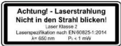
Attention: Laser beam
Do not look into the beam
Laser class 2
Protect yourself and you environment from accidents using suitable precautionary measures!
- Do not look directly into the laser beam with unprotected eyes.
- Never look into the path of the beam.
- Never point the laser beam towards reflecting surfaces and persons or animals. Even a laser beam with a low output can cause damage to the eyes.

CAUTION
Methods other than those specified here can result in dangerous radiation exposure.
- Never open the laser module. Unexpected exposure to the beam can occur.
- If the product is not used for an extended period of time, the batteries should be removed.
- The laser may not be replaced with a different type of laser.
• Repairs of the laser may only be carried out by the laser manufacturer or an authorised representative.
Residual risks
The product has been built according to state-of-the-art and the recognised technical safety rules. However, individual residual risks can arise during operation.
• Health hazard due to electrical power, with the use of improper electrical connection cables.
• Furthermore, despite all precautions having been met, some non-obvious residual risks may still remain.
- Residual risks can be minimised if the "Safety Instructions" and the "Intended Use" together with the operating manual as a whole are observed.
- Prevent the product being unintentionally started up.
- Keep your hands away from the working area when the product is in operation.
- Unintentional starting up of the product.
- Comply with the stipulated maintenance and safety instructions in the operating manual.

WARNING
This power tool generates an electromagnetic field during operation. This field can impair active or passive medical implants under certain circumstances. In order to prevent the risk of serious or deadly injuries, we recommend that persons with medical implants consult with their physician and the manufacturer of the medical implant prior to operating the power tool.
7 Technical data
| Rated voltage 230 - 240V~ 50 Hz | |
| Nominal power 710W (S1*) | 900 W (S6* 10%) |
| Idle speeds n0 | 500 - 2600 rpm |
| Protection class II | |
| Protection category IPX0 | |
| Chuck B16 | (1.5 mm – 13 mm) |
| Max. drilling diameter (depending on the quality of the drill bit) | 13 millimeters |
| Steel: | 40 millimeters |
| Wood: | |
| Drill stroke 70 millimeters | |
| Distance between chuck and floor plate (without tool attachment) | 280 millimeters |
| Swing 125 millimeters | |
| Laser class II | |
| Laser wavelength | 650 nm |
| Laser power | < 1 mW |
| Weight (fully assembled) | 7.6 kg |
Subject to technical changes!
\*Operating mode S1 (continuous operation)
The product can be operated continuously with the specified power.
\*Operating mode S6
Uninterrupted periodic operation. The mode comprises of a start-up period, a time with constant load and an idle time. The operating time is 10 mins, the relative duty cycle is 10% of the operating time.
Noise and vibration

WARNING
Noise can have serious effects on your health. If the machine noise exceeds 85 dB, please wear suitable hearing protection for you and persons in the vicinity.
The noise and vibration values have been determined in accordance with EN 62841-1.
Noise data
| Sound pressure level L_pA | 80.1 dB |
| Measurement uncertainty K_pA | 3 dB |
| Sound power level L_wA | 93.1 dB |
| Measurement uncertainty K_wA | 3 dB |
Vibration parameters (hand/arm vibration)
$$ \text { Vibration } a _ {\mathrm{h}} \leq 2. 5 \mathrm{m} / \mathrm{s} ^ {2} $$
The total vibration emission values specified and the device emissions values specified have been measured in accordance with a standardised test procedure and can be used for comparison of one electric tool with another.
The total noise emission values specified and the total vibration emission values specified can also be used for an initial estimation of the load.

WARNING
The noise emission values can vary from the specified values during the actual use of the power tool, depending on the type and the manner in which the electric tool is used, and in particular the type of workpiece being processed.
Try to keep the stress as low as possible. For example: Limit working time. In doing so, all parts of the operating cycle must be taken into account (such as times in which the power tool is switched off or times in which it is switched on, but is not running under a load).
8 Unpacking

WARNING
The product and the packaging material are not children's toys!
Do not let children play with plastic bags, films or small parts! There is a danger of choking or suffocating!
- Open the packaging and carefully remove the product.
- Remove the packaging material, as well as the packaging and transport safety devices (if present).
- Check whether the scope of delivery is complete.
- Check the product and accessory parts for transport damage. Immediately report any damage to the transport company that delivered the Product. Later claims will not be recognised.
- If possible, keep the packaging until the expiry of the warranty period.
- Familiarise yourself with the product by means of the operating manual before using for the first time.
- With accessories as well as wearing parts and replacement parts use only original parts. Spare parts can be obtained from your specialist dealer.
- When ordering please provide our article number as well as type and year of manufacture for the product.
9 Installation (Fig. 1, 2)

WARNING
Danger of injury!
Only insert the mains plug into the socket when the product is ready for use.

WARNING
Tool attachments may be sharp and become hot during use. Always wear protective gloves when handling the tool attachments.
Some parts of the delivery come disassembled. For quick and easy assembly, read and follow the instructions below.
Tool required:
- Allen key, 4 mm (15)
- Plastic hammer*
* = may not be included in the scope of delivery!
Clean the following parts with a clean and dry cloth:
- Chuck (5)
- Floor plate (7)
- Column tube (9)
9.1 Fitting the column tube (9) (Fig. 3)
- Slide the quick clamp (6) over the column tube (9).
- Insert the column tube (9) in the floor plate (7). Make sure that the guide pin at the lower end of the column tube (9) is inserted into the groove of the mounting of the floor plate (7).
- Fix the column tube (9) to the floor plate (7) using the two pre-assembled M6 grub screws (7a). Use a 4 mm Allen key (15).
9.2 Mounting the handle (2) (Fig. 3)
- Disassemble the pre-assembled M6 screw (2b). Use a 4 mm Allen key (15).
- Ensure that the spacer (2d) is seated correctly.
- Place the handle (2) on the hand spindle guide (2a). Ensure that the hole on the handle (2) aligns with the hole on the hand spindle guide (2a).
- Guide the M6 screw (2b) through the aligned holes and use an M6 nut (2c) to secure it. Use a 4 mm Allen key (15).
9.3 Fitting the depth stop (1) (Fig. 3)
- Insert the depth stop (1) from above into the recess in the housing.
- Fit the clamping lever (12) in the hole provided in the housing.
9.4 Fitting the parallel stop (8) (Fig. 4)
- Slide the parallel stop (8) into the grooves (7b) in the floor plate (7).
- Ensure that the sliding blocks underneath the wing screws (8a) are properly engaged in the grooves (7b).
- Move the parallel stop (8) to the desired position and tighten the wing screws (8a) firmly.
9.5 Inserting the chuck (5) (Fig. 5)
ATTENTION
The chuck is not pre-assembled!
- Attach the chuck (5) in the cone on the drill spindle.
- Tap the chuck tip gently to secure the chuck (5). Use a plastic hammer.
10 Before commissioning

WARNING
Always remove the mains plug before carrying out adjustments on the product.
- 2x open-ended spanner/socket spanner, size 13 mm*
- Phillips screwdriver*
* = may not be included in the scope of delivery!
10.1 Use as a stationary machine (Fig. 4)
The product must be mounted on a workbench for continuous use.
- The product must be securely installed, i.e. bolted down on a workbench or fixed machine stand.
- There are fastening holes in the floor plate (7) for this purpose.
-
Mark the drill holes.
-
Place the product as it will be installed later.
- Mark the positions of the holes to be drilled on the workbench.
They are prescribed by the fastening holes in the floor plate (7).
- Drill the holes (at least 9 mm diameter) through the workbench.
- Place the product over the drilled holes congruent with the fastening holes in the floor plate (7) and insert the screws* (M8) with a suitable length through the holes from above.
- Screw the nuts* (M8) onto the screws* (M8) from below.
- Tighten the nuts* (M8) using two open-end spanners, AF13*.
* = may not be included in the scope of delivery!
10.2 Aligning the workpiece (Fig. 6, 7)
- To switch on the laser cross (13), press the on/off switch (13a) to position "I".
- The intersection of the two laser lines indicates the centre point of the drill.
- Align your marking on the workpiece with the laser cross.
10.3 Clamping the workpiece (Fig. 1, 8)
- Ensure that the workpiece is securely fastened.
- Do not work with workpieces that are to small to be clamped in place.
- Use additional workpiece supports, if required for workpiece stability.
-
The cut-out of the quick clamp (6) must be centrally aligned with the hole to be drilled. Otherwise, the drill bit or the chuck (5) could be obstructed by the quick clamp (6).
-
Turn the quick-clamp screw (6a) anti-clockwise to loosen it.
- Push the quick clamp (6) upwards and swing it to the side to create space for the workpiece.
- Position the workpiece with the help of the laser cross (13) as in 10.2. Ensure that it is aligned so that it remains stable during machining.
- Place the quick clamp (6) on the workpiece.
- Turn the quick clamp screw (6a) clockwise to clamp the workpiece.
- Check that the workpiece is clamped securely and tightly. It must not move.
10.4 Clamping larger workpieces (Fig. 4, 8)
Notes:
- The parallel stop ensures that the workpiece is guided in the desired position. This is particularly advantageous when several holes have to be drilled at an even distance or in a straight line.
-
Use the parallel stop (8) to clamp larger workpieces in a secure manner.
-
Turn the wing screws (8a) of the parallel stop (8) anti-clockwise to loosen them.
- Insert the parallel stop (8) into the grooves (7b) in the floor plate (7).
- Align the workpiece with the parallel stop (8).
- Tighten the wing screws (8a) of the parallel stop (8).
- Clamp the workpiece as described in 10.3.
- Check that the workpiece is clamped securely and tightly. It must not move.

WARNING
With workpieces that are wider or longer than the tabletop, ensure that these are adequately supported, e.g. through trestles or saw horses.
Workpieces that are longer or wider than the floor plate of the product can tip if they are not properly supported. If the workpiece tips, this can damage the chuck or the cutting tool!
10.5 Adjusting the height (Fig. 1)
- Hold the handle (2) firmly.
- Release the clamping lever (11) for the height adjustment.
- Use the handle (2) to adjust the position of the product head.
- Secure the position of the product head with the clamping lever (11).
Otherwise, the gear rack (10) may be damaged.
10.6 Inserting/removing the tool attachment (Fig. 9)

WARNING
Danger of injury!
Only insert the mains plug into the socket when the product is ready for use.

WARNING
Never leave the chuck key inserted in the chuck!
Note:
Check that the tool attachment is fitted securely.
Tool attachments that are not fitted correctly or securely may come loose during operation and injure you.
- You can store the chuck key (14) in the chuck key holder (14a).
- Remove the chuck key (14) from the chuck key holder (14a).
- Use the chuck key (14) to loosen the retaining jaws on the chuck (5).
- Remove the tool attachment*.
- Insert a new tool attachment*.
- Use the chuck key (14) to tighten the retaining jaws on the chuck (5).
- Place the check key (14) back into the chuck key holder (14a).
- Check that the tool attachment* is centred.
- Perform a short test run to check that the tool attachment* for concentricity.
* = may not be included in the scope of delivery!
10.7 Adjusting the drilling depth (Fig. 1, 10)
The drilling depth can be set with the depth stop (1).
- Insert the tool attachment into the chuck (5) as described in 10.6.
- Hold the handle (2) firmly.
- Release the clamping lever (11) for the height adjustment.
- Use the handle (2) on the workpiece to lower the chuck (5) and hold the handle (2) in this position. Make sure that the cutting edge of the tool attachment does not touch the workpiece.
- Retighten the clamping lever (11).
- Release the clamping lever (12) of the depth stop (1).
- Set the desired drilling depth using the depth stop (1).
- Retighten the clamping lever (12).
- Switch the product on (see 11.1).
- Use the handle (2) to lower the chuck (5).
- Drill with appropriate feed up to the pre-set limit stop. Select the correct lubricant based on the workpiece and drill bit materials, as well as the type of hole.
-
Use the handle (2) to return the chuck (5) to the starting position.
-
Then check the position of the depth stop (1). If the indicated dimension does not correspond to the actual drilling depth, the scale indicator (1a) can be readjusted as described in 10.7.1.
- If the set drilling depth is no longer required, release the clamping lever (12) of the depth stop (1).
10.7.1 Readjusting the scale indicator (1a) (Fig. 10)
- Loosen the cross-head screw (1b) of the scale indicator (1a). Use a Phillips screwdriver.
- Make sure the scale indicator (1a) is correctly seated.
- Re-tighten the Phillips screw (1b).
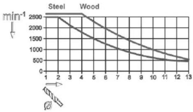
10.8 Setting the speed (Fig. 1)
Use the electronic speed control to steplessly set the speed:
- Set the speed with the help of the speed control (4).
- You can read the current speed from the mark on the speed controller (4).
line
| Time | Steel (min⁻¹) | Wood (min⁻¹) | |------|---------------|--------------| | 1 | 2600 | 2600 | | 2 | 2600 | 2600 | | 3 | 2600 | 2600 | | 4 | 2600 | 2600 | | 5 | 2600 | 2600 | | 6 | 2600 | 2600 | | 7 | 2600 | 2600 | | 8 | 2600 | 2600 | | 9 | 2600 | 2600 | | 10 | 2600 | 2600 | | 11 | 2600 | 2600 | | 12 | 2600 | 2600 | | 13 | 2600 | 2600 |11 Operation
ATTENTION
Always make sure the product is fully assembled before commissioning!

WARNING
Danger of injury!
Only insert the mains plug into the socket when the product is ready for use.

WARNING
Tool attachments may be sharp and become hot during use. Always wear protective gloves when handling the tool attachments.
Notes:
- Before connecting of the product, make certain that the data on the type plate matches with the mains power data.
- Remember that when the starter mechanism with motorised products is commissioned, the cutting tool also starts operating.
- Before switching on, make sure that the tool attachment is not touching the workpiece.
- Check the material to be processed for foreign objects such as nails, screws etc. and remove them.
• After switching on, wait until the product has reached its desired speed. Only then should you start working.
11.1 Switching the product on/off (Fig. 1)
Switching on
- Insert the mains plug into a properly fused mains socket.
- Press the "I" switch on the on/off switch (3) to switch the product on.
Switching off
- Press the "0" switch on the on/off switch (3) to switch the product off.
- Wait until the product has come to a standstill.
12 Working instructions
ATTENTION
The feed and the spindle speed are decisive for the attachment tool's service life!
- The cutting speed is determined by the drill spindle speed and the diameter of the attachment tool.
- In principle, the greater the attachment tool diameter, the lower the speed should be.
- The stronger the workpiece, the higher the cutting pressure must be.
- Pulling the attachment tool back repeatedly ensures that the chips can be removed easier.
- Chip removal is made more difficult in deeper holes in particular. Reduce the feed and the speed here.
- In order to prevent excessive wear to the attachment tool cutting edge, first pre-drill holes with a diameter of more than 8.0 mm using an attachment tool with a smaller diameter.
12.1 Drilling (Fig. 1)
-
Position the workpiece with the help of the laser cross (13) and clamp it (see 10.3).
-
Insert a tool attachment into the chuck (5) (see 10.6).
- Use the handle (2) to lower the chuck (5) and centre the tool attachment over the point to be drilled on the workpiece.
- Switch the product on (see 11.1).
- Use the handle (2) to lower the chuck (5).
- Drill into the workpiece with an appropriate feed and to the required depth.
- Select the correct lubricant based on the workpiece and drill bit materials, as well as the type of hole.
- Ensure any required chip breaking on the way to the required drilling depth.
- Use the handle (2) to guide the chuck (5) back to the starting position slowly.
* = may not be included in the scope of delivery!
12.2 Countersinking and centre drilling
You can also use this product for countersinking or centre drilling.
Note that countersinking must be performed at the lowest speed while a high speed is required for centre drilling.
12.3 Replacing the chuck (Fig. 5, 9)
Note:
When replacing the chuck, use only chucks approved by the manufacturer.
Tool required:
- Open-ended spanner AF 27 mm*
- Remove the tool attachment as described in 10.6.
- Lock the chuck (5) with the chuck key (14).
- Place an open-ended spanner AF 27 mm on the nut (5a) and turn it downwards in a clockwise direction until the chuck (5) separates from the drill spindle.
- Turn the nut (5a) all the way back up to the drill spindle.
- Fix the new chuck (5) as described in 9.5.
13 Cleaning and maintenance

WARNING
Have maintenance and repair tasks that are not described in this operating manual, carried out by a specialist workshop. Use only original spare parts.

WARNING
Improper maintenance or cleaning work can cause injuries!

WARNING
The product may start unexpectedly and cause injuries and burns during cleaning, repair and maintenance work.
- Switch the product off.
– Pull out the mains plug. - Allow the product to cool.
- Remove the tool attachment.
13.1 Cleaning
- Keep protective devices, air vents and the motor housing as free of dust and dirt as possible. Rub the product clean with a clean cloth* or blow it off with compressed air* at low pressure. We recommend that you clean the product directly after every use.
- Never immerse the product in water or other liquids for cleaning.
- Always keep the product clean, dry and free from oil or grease. Remove dust after each use and before storage.
- Do not use chemical, alkaline, abrasive or other aggressive cleaning agents or disinfectants to clean the product, as these may damage the surfaces.
- Do not clean the tool attachment while it is still in operation.
13.2 Maintenance
The product is maintenance-free.
14 Electrical connection
The electrical motor installed is connected and ready for operation. The connection complies with the applicable VDE and DIN provisions. The customer's mains connection as well as the extension cable used must also comply with these regulations.
14.1 Damaged electrical connection cables
The insulation on electrical connection cables is often damaged.
This may have the following causes:
- Pressure points, where connection cables are passed through windows or doors,
- Kinks where the connection cable has been improperly fastened or routed,
- Places where the connection cables have been cut due to being driven over,
- Insulation damage due to being ripped out of the wall socket,
- Cracks due to the insulation ageing.
Such damaged electrical connection cables must not be used and are life-threatening due to the insulation damage.
Check the electrical connection cables for damage regularly. Ensure that the connection cables are disconnected from electrical power when checking for damage.
Electrical connection cables must comply with the applicable VDE and DIN provisions. Only use connection cables of the same designation.
The printing of the type designation on the connection cable is mandatory.
Safety information for replacing damaged or defective mains connection cables
Connection type Y
If it is necessary to replace the mains connection cable, this must be done by the manufacturer or their representative to avoid safety hazards.
14.2 AC motor
Connections and repair work on the electrical equipment may only be carried out by electricians.
- The mains voltage must be 230 V\~
- Extension cables up to 25 m long must have a cross-section of 1.5 mm ^2 .
15 Transport (Fig. 1)
- To transport the product, disconnect the it from the power supply and set it up in the new position you want to use it in.
- The product must be secured against tipping and slipping during transport in vehicles in order to prevent damage and injuries.
- Protect the product from impacts, shocks and severe vibrations, e.g. during vehicular transport.
- Do not transport the product by the motor unit.
Note:
Carry the product together with a second person if possible.
- Reach under the floor plate (7) with one hand and use the other hand to stabilise the product on the housing.
16 Storage
Store the product and its accessories in a dark, dry and frost-free place that is inaccessible to children.
The optimum storage temperature is between 5^ C and 30^ C.
Store the product in its original packaging.
Cover the product to protect it from dust or moisture. Store the operating manual with the product.
17 Repair and ordering spare parts
After repairs or maintenance, make sure that all safety-related parts are installed and are in perfect condition.
All parts which may cause injury must be kept where they are inaccessible to children or others.
ATTENTION
According to the German Product Liability Act, no liability is accepted for damage caused by improper repairs or by not using original spare parts.
Such work should be performed by a customer service centre or an authorised specialists. The same applies to accessory parts.
Spare parts and accessories can be obtained from our Service Centre. To do this, scan the QR code on the front page.
Connections and repairs
Connections and repair work on the electrical equipment may only be carried out by electricians.
17.1 Ordering spare parts
Please provide the following information when ordering spare parts:
- Model designation
- Item number
- Type plate data
Spare parts / accessories
| Chuck article no.: 3906814001 | |
| Chuck key article no.: 3906814014 | |
| Parallel stop-Article no.: 3906813020 | |
| Depth stop-Article no.: 3906814013 | |
| Scale indicator-Article no.: 3906814012 | |
| Clamping lever (Height stop/Depth stop)-Article no.: | 05006250 |
| Quick clamp -Article no.: 3906813021 | |
| Carbon brushes-Article no.: | 39068249009 |
| Handle-Article no.: | 3906816004 |
18 Disposal and recycling
Notes for packaging


The packaging materials are recyclable. Please dispose of packaging in an environmentally friendly manner.
Notes on the electrical and electronic equipment act [ElektroG]
![PARKSIDE PTBMOD 710 D1 - Notes on the electrical and electronic equipment act [ElektroG] - 1](/content/2026/04/738787/images/df3773355b31ae0ff1af506aa7d8f09a26181bef5a76715290e72ca64b7de1e5.jpg)
Waste electrical and electronic equipment does not belong in household waste, but must be collected and disposed of separately!
- Used batteries or rechargeable batteries that are not installed permanently in the old device must be removed non-destructively before disposal! Their disposal is regulated by the battery act.
- Owners or users of electrical and electronic devices are legally obliged to return them after use.
- The end user is responsible for deleting their personal data from the old device being disposed of!
- The symbol of the crossed-out dustbin means that waste electrical and electronic equipment must not be disposed of with household waste.
- Waste electrical and electronic equipment can be handed in free of charge at the following places:
– Public disposal or collection points (e.g. municipal works yards)
- LIDL offers you return options directly in the shops and markets. Return and disposal are free of charge.
- Up to three waste electrical devices per type of device, with an edge length of no more than 25 centimetres, can be returned free of charge to the manufacturer without prior purchase of a new device from the manufacturer or taken to another authorised collection point in your vicinity.
- Further supplementary take-back conditions of the manufacturers and distributors can be obtained from the respective customer service.
- If the manufacturer delivers a new electrical device to a private household, the manufacturer can arrange for the free collection of the old electrical device upon request from the end user. Please contact the manufacturer's customer service for this.
- These statements only apply to devices installed and sold in the countries of the European Union and which are subject to the European Directive 2012/19/EU. In countries outside the European Union, different regulations may apply to the disposal of waste electrical and electronic equipment.
19 Troubleshooting
| Fault Possible cause Remedy | ||
| Motor does not start. On/off switch | tch damaged Replace all damage | maged parts before you use your bench drill again. Contact your local service centre or an authorised service station. Every attempt to carry out a repair, can be dangerous if it is not done by skilled personnel. |
| Damaged mains cable. | ||
| Heavy vibrations Tool attachment | not clamped centrally | Check the tool attachment in the chuck |
| The motor runs slowly and does not reach the operating speed. | Voltage too low, coils damaged, capacitor burnt. | Have the voltage checked by a qualified electrician. Arrange for inspection of the motor by a specialist. Arrange for replacement of the capacitor by a specialist. |
| Engine producing excessive noise. | Coils damaged, motor defective. | Arrange for inspection of the motor by a specialist. |
| Motor overheats easily. | Overloading of the motor, insufficient cooling of the motor | Prevent the motor overloading, keep ventilation slots clear to ensure optimum motor cooling |
| The product becomes slower during work | Too much pressure is applied to the workpiece. | Apply less pressure to the workpiece. |
| The motor does not reach its full power. | Circuits in the network are overloaded (lamps, other motors, etc.). | Do not use any other products or motors on the same circuit. |
20 EU Declaration of Conformity
Translation of the original Declaration of Conformity
Manufacturer:
Scheppach GmbH
Günzburger Straße 69
D-89335 Ichenhausen
We declare under our sole responsibility that the product described here complies with the applicable directives and standards.
Brand: PARKSIDE
Art. designation: Bench Pillar Drill with
Electronic Speed Control – PTBMOD 710 D1
Item No. 3906824974, 3906824975,
3906824977-3906824981, 39068249915, 39068249959
IAN no. 477764_2410
Series no. 01001-25208
EU directives:
2006/42/EG, 2014/30/EU, 2011/65/EU*, (EU) 2015/863
* The object of the declaration described above fulfils the regulations of the directive 2011/65/EU of the European Parliament and Council from 8th June 2011, on the restriction of the use of certain hazardous substances in electrical and electronic equipment.
Applied standards:
EN 62841-1:2015/A11:2022;
EN 62841-3-13:2017;
EN IEC 55014-1:2021;
EN IEC 55014-2:2021;
EN IEC 61000-3-2:2019/A1:2021/A2:2024;
EN 61000-3-3:2013/A1:2019/A2:2021
EN IEC 63000:2018
Documentation authorised representative:
Tobias Ihle
Günzburger Str. 69
D-89335 Ichenhausen
Division Manager Product Center

Head of Project Management
Warranty certificate
Dear Customer,
All of our products undergo strict quality checks to ensure that they reach you in perfect condition. In the unlikely event that your device develops a fault, please contact our service department at the address shown on this guarantee card. Of course, if you would prefer to call us then we are also happy to offer our assistance under the service number printed below. Please note the following terms under which guarantee claims can be made:
- These guarantee terms cover additional guarantee rights and do not affect your statutory warranty rights. We do not charge you for this guarantee.
- Our guarantee only covers problems caused by material or manufacturing defects, and it is restricted to the rectification of these defects or replacement of the device. Please note that our devices have not been designed for use in commercial, trade or industrial applications. Consequently, the guarantee is invalidated if the equipment is used in commercial, trade or industrial applications or for other equivalent activities. The following are also excluded from our guarantee: compensation for transport damage, damage caused by failure to comply with the installation/assembly instructions or damage caused by unprofessional installation, failure to comply with the operating instructions (e.g. connection to the wrong mains voltage or current type), misuse or inappropriate use (such as overloading of the device or use of non-approved tools or accessories), failure to comply with the maintenance and safety regulations, ingress of foreign bodies into the device (e.g. sand, stones or dust), effects of force or external influences (e.g. damage caused by the device being dropped) and normal wear resulting from proper operation of the device.
The guarantee is rendered null and void if any attempt is made to tamper with the device.
- The guarantee is valid for a period of 3 years starting from the purchase date of the device. Guarantee claims should be submitted before the end of the guarantee period within two weeks of the defect being noticed. No guarantee claims will be accepted after the end of the guarantee period. The original guarantee period remains applicable to the device even if repairs are carried out or parts are replaced. In such cases, the work performed or parts fitted will not result in an extension of the guarantee period, and no new guarantee will become active for the work performed or parts fitted. This also applies when an on-site service is used.
- In order to assert your guarantee claim, please contact the service partner shown below. If the complaint is within the guarantee period, we will provide you with a return slip, with which you can return your defective device free of charge to us. It would help us if you could describe the nature of the problem in as much detail as possible. If the defect is covered by our guarantee then your device will either be repaired immediately and returned to you, or we will send you a new device.
Of course, we are also happy offer a chargeable repair service for any defects which are not covered by the scope of this guarantee or for units which are no longer covered. To take advantage of this service, please send the device to our service address.
Processing of warranty claims
To ensure that your request is processed quickly, please follow the instructions below:
- Please have the receipt and article number (e.g. IAN 477764_2410) ready as proof of purchase for all enquiries.
- Please refer to the type plate on the product, an engraving on the product, the title page of your instructions (bottom left) or the sticker on the back or underside of the product for the article number.
- If functional faults or other defects occur, first contact the service department named below by telephone or e-mail.
- You can then send a product recorded as defective to the service address provided to you free of charge, enclosing the proof of purchase (receipt) and stating what the defect is and when it occurred.
- You can view and download these and many other manuals at parkside-diy.com. This QR code will take you directly to parkside-diy.com. Select your country and

PDF ONLINE
parkside-diy.com
use the search mask to search for the operating instructions. Enter the article number (IAN) 477764_2410 to access the operating instructions for your article.
Service contact (GB): Service contact (IE):
Name: Forest Park & Garden
Coed Court,
Taffsmead Road
Treforest, Ind. Estate,
Pontypridd CF375SW
Name: Forest Park & Garden
Coed Court,
Taffsmead Road
Treforest, Ind. Estate,
Pontypridd CF375SW
Tel: 00800 4003 4003 Tel: 00800 4003 4003
E-Mail: service.GB@scheppach.com E-Mail: service.IE@scheppach.com
Location: Great Britain Location: Great Britain
Service contact (NI): Service contact (CY):
Name: Forest Park & Garden
Coed Court,
Taffsmead Road
Treforest, Ind. Estate,
Pontypridd CF375SW
Name: GEORGE C SOLOMONIDES
& SON LTD
PO.BOX 56236 / 169, LEONTIOS A'
GR - 3022 LIMASSOL/CYPRUS
Tel: 00800 4003 4003 Tel: 00800 4003 4003
E-Mail: service.Nl@scheppach.com E-Mail: service.CY@scheppach.com
Location: Great Britain Location: Cyprus
Service contact (IT):
Name: Netsend GmbH
Nachtwaid 6
DE - 79206 Breisach am Rhein
Tel: 00800 4003 4003
E-Mail: service.IT@scheppach.com
Location: Germany
Inhaltsverzeichnis
Günzburger Straße 69
D-89335 Ichenhausen
Verehrter Kunde
• Gabelschlüssel SW 27 mm*
15 Transport (Abb. 1)
Günzburger Straße 69
D-89335 Ichenhausen
Division Manager Product Center

Head of Project Management
Garantieurkunde
PDF ONLINE
parkside-diy.com
Servicekontakt (DE): Servicekontakt (AT):
Günzburger Straße 69
D-89335 Ichenhausen
Cher client,
15 Transport (fig. 1)
Günzburger Straße 69
D-89335 Ichenhausen
Division Manager Product Center

Andreas Pecher
Head of Project Management
Certificat de garantie
Chère Cliente, Cher Client,
PDF ONLINE
parkside-diy.com
15 Transport (afb. 1)....63
16 Opslag.... 63
Günzburger Straße 69
D-89335 Ichenhausen
Geachte klant,
15 Transport (afb. 1)
Günzburger Straße 69
D-89335 Ichenhausen
Division Manager Product Center

Andreas Pecher
Head of Project Management
Garantiebewijs
Geachte klant,
Servicecontact (NL): Servicecontact (BE):
Naam: TeleMarCom
Naam: TeleMarCom
European Services GmbH
European Services GmbH
Am Ziegelweiher 24
Am Ziegelweiher 24
DE - 61130 Nidderau
DE - 61130 Nidderau
Telefoon: 00800 4003 4003 Telefoon: 00800 4003 4003
E-mail: service.NL@scheppach.com E-mail: service.BE@scheppach.com
Günzburger Straße 69
Günzburger Straße 69
D-89335 Ichenhausen
Division Manager Product Center

Andreas Pecher
Head of Project Management
PDF ONLINE
parkside-diy.com
Günzburger Straße 69
D-89335 Ichenhausen, Germania
Egregio cliente,
Günzburger Straße 69
D-89335 Ichenhausen
Division Manager Product Center

Andreas Pecher
Head of Project Management
PDF ONLINE
parkside-diy.com
Günzburger Straße 69
D-89335 Ichenhausen
Vážený zákazníku,
Günzburger Straße 69
D-89335 Ichenhausen
Division Manager Product Center

Andreas Pecher
Head of Project Management
Záruční list
Važena zakaznice, važeny zakazniku,
Günzburger Straße 69
D-89335 Ichenhausen
Vážený zákazník,
Günzburger Straße 69
D-89335 Ichenhausen
Division Manager Product Center

Andreas Pecher
Head of Project Management
Záručný list
Günzburger Straße 69
D-89335 Ichenhausen
Tisztelt Ügyfelünk!
Günzburger Straße 69
D-89335 Ichenhausen
Division Manager Product Center

Andreas Pecher
Head of Project Management
JÓTÁLLÁSI TÁJÉKOZTATÓ
PDF ONLINE
parkside-diy.com
Günzburger Straße 69
D-89335 Ichenhausen
Szanowny Kliencie
15 Transport (rys. 1)
Günzburger Straße 69
D-89335 Ichenhausen
Division Manager Product Center

Andreas Pecher
Head of Project Management
Gwarancja
Drodzy Klienci,
PDF ONLINE
parkside-diy.com
Kontakt z serwisem (PL):
Günzburger Straße 69
D-89335 Ichenhausen, Tyskland
Kære kunde
15 Transport (fig. 1)
Günzburger Straße 69
D-89335 Ichenhausen, Tyskland
Division Manager Product Center

Andreas Pecher
Head of Project Management
Garantibevis
Kære kunde,
PDF ONLINE
parkside-diy.com
Notizen
CE
SCHEPPACH GMBH
Günzburger Str. 69
D-89335 Ichenhausen


FSC
www.fsc.org
MIX
Paper from responsible sources
C173905 C173905 C173905 C ^10

FSC
www.fsc.org
MIXTE



- BENCH PILLAR DRILL WITH ELECTRONIC SPEED CONTROL PTBMOD 710 D1 TISCHBOHRMASCHINE MIT ELEKTRONISCHER DREHZAHLREGELUNG PTBMOD 710 D1 PERCEUSE À COLONNE AVEC RÉGLAGE ÉLECTRONIQUE PTBMOD 710 D1
- DE AT CH
- Explanation of the symbols on the product
- Introduction
- Manufacturer:
- Dear Customer
- Note:
- Product description (Fig. 1-10)
- Scope of delivery (Fig. 2)
- Item Quantity Designation
- Proper use
- Explanation of the signal words in the operating manual
- DANGER
- WARNING
- CAUTION
- ATTENTION
- Safety instructions
- Save all warnings and instructions for future reference.
- 1) Work area safety
- 2) Electrical safety
- 3) Personal safety
- 4) Power tool use and care
- 5) Service
- Safety instructions for transportable drills
- Laser beam
- Protect yourself and you environment from accidents using suitable precautionary measures!
- Methods other than those specified here can result in dangerous radiation exposure.
- Residual risks
- The product has been built according to state-of-the-art and the recognised technical safety rules. However, individual residual risks can arise during operation.
- Technical data
- \*Operating mode S1 (continuous operation)
- \*Operating mode S6
- Noise and vibration
- Vibration parameters (hand/arm vibration)
- Unpacking
- Installation (Fig. 1, 2)
- Danger of injury!
- Fitting the column tube (9) (Fig. 3)
- Mounting the handle (2) (Fig. 3)
- Fitting the depth stop (1) (Fig. 3)
- Fitting the parallel stop (8) (Fig. 4)
- Inserting the chuck (5) (Fig. 5)
- Before commissioning
- Use as a stationary machine (Fig. 4)
- Aligning the workpiece (Fig. 6, 7)
- Clamping the workpiece (Fig. 1, 8)
- Clamping larger workpieces (Fig. 4, 8)
- Notes:
- Adjusting the height (Fig. 1)
- Inserting/removing the tool attachment (Fig. 9)
- Check that the tool attachment is fitted securely.
- Adjusting the drilling depth (Fig. 1, 10)
- Readjusting the scale indicator (1a) (Fig. 10)
- Setting the speed (Fig. 1)
- Operation
- Switching the product on/off (Fig. 1)
- Switching on
- Switching off
- Working instructions
- Drilling (Fig. 1)
- Countersinking and centre drilling
- Replacing the chuck (Fig. 5, 9)
- Cleaning and maintenance
- Cleaning
- Maintenance
- Electrical connection
- Damaged electrical connection cables
- Safety information for replacing damaged or defective mains connection cables
- Connection type Y
- AC motor
- Transport (Fig. 1)
- Storage
- Repair and ordering spare parts
- Connections and repairs
- Ordering spare parts
- Disposal and recycling
- Notes for packaging
- Notes on the electrical and electronic equipment act [ElektroG]
- Troubleshooting
- EU Declaration of Conformity
- Translation of the original Declaration of Conformity
- EU directives:
- Applied standards:
- Documentation authorised representative:
- Warranty certificate
- Dear Customer,
- Processing of warranty claims
- Service contact (GB): Service contact (IE):
- Service contact (NI): Service contact (CY):
- Service contact (IT):
- Inhaltsverzeichnis
- Verehrter Kunde
- Transport (Abb. 1)
- Garantieurkunde
- Servicekontakt (DE): Servicekontakt (AT):
- Cher client,
- Certificat de garantie
- Chère Cliente, Cher Client,
- Geachte klant,
- Transport (afb. 1)
- Garantiebewijs
- Egregio cliente,
- Vážený zákazníku,
- Záruční list
- Važena zakaznice, važeny zakazniku,
- Vážený zákazník,
- Andreas Pecher
- Záručný list
- Tisztelt Ügyfelünk!
- Szanowny Kliencie
- Transport (rys. 1)
- Gwarancja
- Drodzy Klienci,
- Kære kunde
- Garantibevis
- Kære kunde,
- Notizen
- CE
Brand : PARKSIDE
Model : PTBMOD 710 D1
Category : Drill