Capas 2 - Saw SCHEPPACH - Free user manual and instructions
Find the device manual for free Capas 2 SCHEPPACH in PDF.

User questions about Capas 2 SCHEPPACH
0 question about this device. Answer the ones you know or ask your own.
Ask a new question about this device
Download the instructions for your Saw in PDF format for free! Find your manual Capas 2 - SCHEPPACH and take your electronic device back in hand. On this page are published all the documents necessary for the use of your device. Capas 2 by SCHEPPACH.
USER MANUAL Capas 2 SCHEPPACH
natural_image
Green and black cutting tool with red-handled blade and metal workpiece, no visible text or symbolsscheppach
Contents
| GB | 1-4 |
| D | 5-9 |
| FR | 10-14 |
| NL | 15-19 |
| DK | 20-24 |
| I | 25-29 |
| PT | 30-34 |
text_image
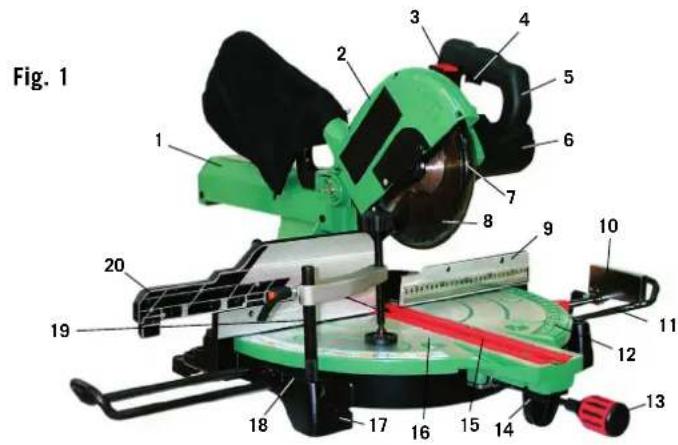
Fig. 1 1 2 3 4 5 6 7 8 9 10 11 12 13 14 15 16 17 18 19 20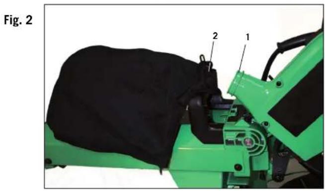
natural_image
Green agricultural machine component with black fabric and labeled parts (1, 2), no visible text or symbols beyond labels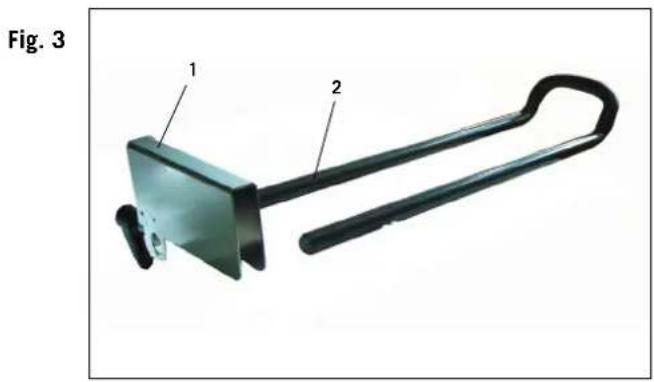
natural_image
Diagram of a metal tool with labeled parts, showing a handle and bracket (no text or symbols present)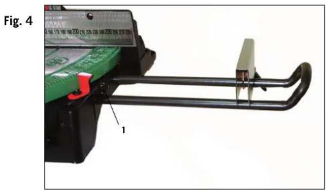
text_image
Fig. 4 1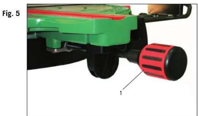
natural_image
Close-up of a green and red robotic device with a red handle and labeled component '1' (no text or symbols on the device itself)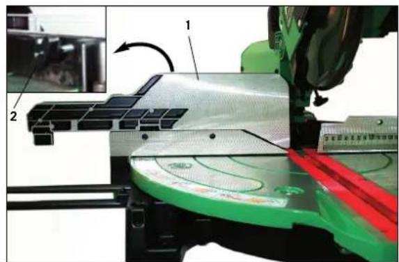
natural_image
Close-up of a robotic arm cutting a green and red plastic component on a workbench, with no visible text or symbols.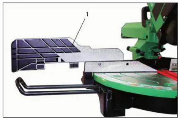
natural_image
Mechanical assembly diagram showing a green robotic arm interacting with a multi-panel solar panel and mechanical components (no text or symbols visible)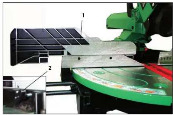
natural_image
Close-up of a green robotic arm assembling solar panels on a green cutting board (no visible text or symbols)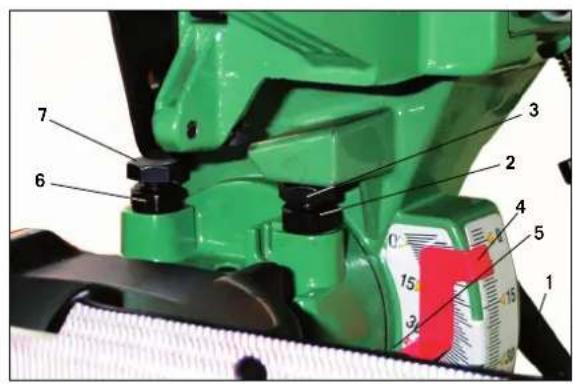
text_image
Labeled diagram of a green industrial machine with numbered components and a red scale showing measurement markings.
natural_image
Close-up of a green 3D-printed printer cutting through a metal ruler, no visible text or symbols on the device itself.General Safety Rules
WARNING! When using electric tools basic safety precautions should always be followed to reduce the risk of fire, electric shock and personal injury.
Read all these instructions before attempting to operate this product. Save these instructions for future reference.
- Keep work area clear. Cluttered areas and benches invite injuries.
- Consider work area environment. Do not expose tools to rain. Do not use tools in damp or wet locations. Keep work area well lit. Do not use tools in the presence of flammable liquids or gases.
- Guard against electric shock. Avoid body contact with earthed or grounded surfaces.
- Keep other people away. Do not let others, especially children, get involved in the work touch the tool or the extension lead and keep them away from the work area.
- Store idle tools. When not in use, tools should be stored in a dry locked-up place, out of reach of children.
- Do not force the tool. It will do the job better and safer at the rate for which it was intended.
- Use the right tool. Do not force small tools to do the job of a heavy duty tool. Do not use tools for purposes not intended; for example do not use circular saws to cut tree limbs or logs.
- Dress properly. Do not wear loose clothing or jewellery they can be caught in moving parts. Non-skid footwear is recommended when working outdoors. Wear protective hair covering to contain long hair.
- Use protective equipment. Use safety glasses. Use face or dust mask if cutting operations create dust.
- Connect dust extraction equipment. If devices are provided for the connection of dust extraction and collecting equipment, ensure these are connected and properly used.
- Do not abuse the cable. Never pull the power cable to disconnect it from the socket. Keep the cable away from heat, oil and sharp edge.
- Secure work. Where possible use clamps or a vice to hold the work. It's safer than using your hand.
- Don't over reach. Keep proper footing and balance at all time.
- Maintain tools with care. Keep cutting tools sharp and clean for better and safer performance. Follow instructions for lubricating and changing accessories. Inspect power cables periodically and if damaged have them replaced by an authorised service facility. Inspect extension cables periodically and replace if damaged. Keep handles dry, clean and free from oil and grease.
- Disconnect tools. When not in use, before servicing and when changing accessories such as blades, bits, cutters, disconnect tools from the power supply.
- Remove adjusting keys and wrenches. Form the habit of checking to see that keys and adjusting wrenches are removed from the tool before turning it on.
- Avoid unintentional starting. Ensure switch is in 'off' position when plugging in.
-
Use outdoor extension leads. When the tool is used outdoors, use only extension leads intended for outdoor use and so marked.
-
Stay alert. Watch what you are doing, use common sense and do not operate the tool when you are tired.
- Check damaged parts. Before further use of the tools, it should be carefully checked to determine that it will operate properly and perform its intended function. Check the alignment of moving parts, binding of moving parts, breakage of parts, mounting and any other conditions that may affect its operation. A guard or other part that is damaged should be properly repaired or replaced by an authorised service centre unless otherwise indicated in this instruction manual. Do not use the tool if the switch does not turn on and off.
- Warning. The use of any accessory or attachment other than one recommended in this instruction manual may present a risk of personal injury.
- Have your tool repaired by a qualified person. This electric tool complies with the relevant safety rules. Repairs should only be carried out by a qualified person using original spare parts, otherwise this may result in considerable danger to the user.
Additional Safety Rules For Mitre Saws
- Do not use saw blades which are damaged or deformed.
- Do not use the saw without guards in position.
- Replace the table insert when worn.
- Do not use the saw to cut anything other than wood or similar materials.
- Use only saw blades recommended by the manufacturer according to EN847-1.
- Connect your mitre saw to a dust collecting device when sawing.
- Select saw blades in relation to the material to be cut.
- Check the maximum depth of cut.
- When sawing long work pieces, always use extension wings to provide better support, and use clamps or other clamping devices.
- Wear ear protection.
WARNING! Noise can be a health hazard. When the noise level exceeds 85dB(A), be sure to wear ear protection.
Installation
Know your Pullover Mitre Saw (Fig. 1)
- Pullover carriage
- Motor
- Upper blade guard
- Lower blade guard lock lever
- Trigger switch
- Handle
- Lower blade guard
- Tungsten Carbide Tipped blade
- End Stop
- Extension support (optional)
- Mitre scale
- Mitre lock knob
- Table support
- Table insert
- Turn table
- Bolt holes
- Base
- Clamp
- Fence
- Extension fence
Technical Data
Motor 1120 W, 230V \~ 50Hz
Blade ∅ 216 mm; ∅ 30 mm Bore
No load speed 5000 min
Turn table ∅ 525 mm
Mitre stops 0°, 15°, 22.5°, 31.6°,
45° left & right
Mitre angle range 48° left & right
Bevel angle range -3° to 50°
Weight 23 kg
Max. Capacity
Cross Cut at 90° 65 x 320 mm
Mitre cut at 45° 65 x 220 mm
Bevel cut at 45° 45 x 320 mm
Compound cut at 45° 45 x 220 mm
The noise levels of this machine during cutting are as follows:
maximum sound pressure level: 99dB(A)
Assembly
WARNING! For your own safety, never connect the plug to power source outlet until all assembly steps are completed and you have read and understood the safety and operational instructions.
Lift the saw from the packaging and place it on your work bench.
Installing the Dust Bag
- Squeeze the metal collar wings ② of the dust bag and put it on the motor area exhaust port ①. (Fig. 2)
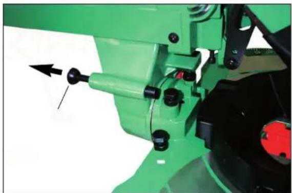
Installing the Extension Supports (Optional)
- Slide the End Stop ① onto the back rail ② of the Extension Support. (Fig. 3)
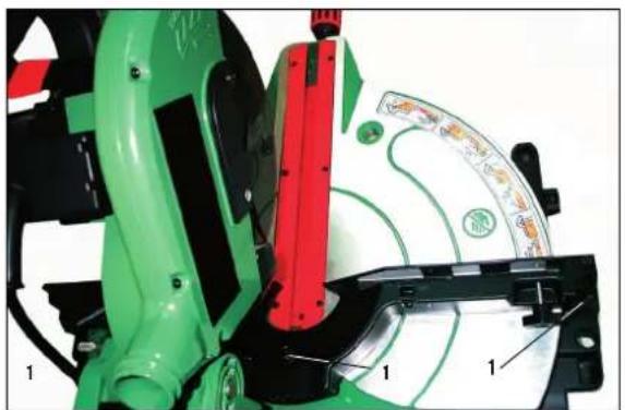
- Tighten the screw ① to lock the Extension Support. (Fig. 4)
- The Fig. 3 and 4 only show the installation of the right extension support. Repeat these procedures for the left extension support.
- The End Stop may be installed on either side of the extension supports.
Note:
Installing the Extension Fence
- For mitre cuts, install the Extension Fence ① close to the saw blade and tighten the lock knob ②. (Fig. 6)
- For bevel or compound cuts, install the Extension Fence ① some distance from the saw blade. (Fig. 7)
- For crown moulding cut, turn the Extension Fence ① close to the saw blade. Tighten the lock knob (Fig. 8)
Setting the Tool
Note:
This tool is accurately adjusted before shipping from the factory. Check the following accuracy and readjust if necessary in order to obtain the best results in operation.
Adjusting the Bevel Stops at 90° and 45° (Fig. 9)
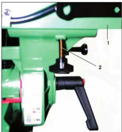
- Loosen the Bevel Lock Handle and move the cutting head all the way to the right and tighten the Bevel Lock Handle ①.
- Use a square to set the blade at 90^ to the table.
- If an adjustment is necessary, loosen the lock nut ② and adjust the bolt ③ using the supplied wrench so that the blade is 90^ to the table.
- Tighten the lock nut.
- Adjust the bevel indicator ④ to the 0 mark using the screw ⑤.
- To adjust the 45^ stop, follow the same procedure as the 90^ but move the cutting head to the left and use the lock nut ⑥ and bolt ⑦.
Adjusting the Fence
- Lower the cutting head and push in the lock pin. Make sure the table is in 0 mitre position.
- Place a combination square against the fence and next to the saw blade. (Fig. 10).
- If the blade does not contact the square, loosen the three screws ①. (Fig. 11)
- Adjust the fence so that the fence has full contact with the square. Tighten the screws.
Connecting to the Power Supply
Check that the power supply and outlet used are in accordance with your mitre saw. Have a look at the rating plate of the motor or the rating on the mitre saw. Any changes should always be carried out by a qualified electrician.
This is a double insulated tool which eliminates the need for an earthed power supply system.
WARNING! Avoid contact with the terminals on the plug when installing (removing) the plug to (from) the power supply outlet. Contact will cause a severe electrical shock.
Using an Extension Lead
The use of any extension lead will cause some loss of power. To keep this to a minimum and to prevent overheating and possible motor burn-out, ask advice from a qualified electrician to determine the minimum wire size of the extension lead.
The extension lead should be equipped with an earthed type plug that fits the power supply outlet at one end, and with an earthed type socket that fits the plug of this machine at the other end.
Mounting the Tool
Note:
We highly recommend that you bolt this mitre saw securely to a work bench to gain the maximum stability of your machine.
- Locate and mark the four bolt holes on the bench.
- Drill the bench with a 10 mm drill bit,
- Bolt the mitre saw on to the bench with bolts, washers and nuts. Note that these fasteners are not supplied with the machine.
Operating the Tool
WARNING! Never connect the plug to the power source outlet until all Installations and adjustments are completed and you have read and understood the safety and operational instructions.
Basic Pullover Mitre Saw Operations
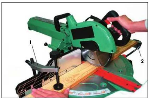
- Always use the clamp ① to hold the work piece firmly. Six holes are provided for the clamp. The End Stop ② is useful when making repetitive cuts. (Fig. 12)
- Always position the work piece against the fence. Any piece that is bowed or warped and cannot be held flat on the table or against fence may trap the blade and should not be used.
- Never place hands near the cutting area. Keep hands outside the "No Hands Zone" which includes the entire table and is labelled by "No Hands" symbols.
WARNING! To avoid injury from materials being thrown, unplug the saw to avoid accidental starting, and then remove small materials.
Chop Cut
- For chop cutting, slide the cutting head to the rear position as far as it will go, and lock the carriage ① by the lock handle ②. (Fig. 14)
Mitre Cut
- Make sure the extension fence is secured in the correct position. (Fig. 6)
-
Loosen the Mitre Lock Knob and move the table to the desired angle. For angles of 0^ , 15^ , 22.5^ , 31.6^ , and 45^ , the table will stop by itself. Tighten the mitre lock knob. (Fig. 13)
-
Activate the switch, then press the blade guard lock lever to lower the cutting head down.
Bevel Cut
- Turn the Extension Fence and install it far from the saw blade. (Fig. 7)
- Loosen the bevel lock handle and move the cutting head to the desired angle. Tighten the bevel lock handle.
- Activate the switch, then press the blade guard lock lever to lower the cutting head down.
Note:
- A special bevel angle 33.9^ stop device is fitted to this mitre saw for special crown moulding. When this angle is required, place the lock pin ① into the slot whilst turning the bevel angle to 33.9^ . (Fig. 15)
Compound Cut
- A compound cut is a combination of mitre cut and bevel cut. Refer to the above procedures to perform this cut.
Base Moulding
- Base moulding can be cut vertically against fence or flat on the table. Follow the table below for reference.
| SETTINGS | Vertical Position(Back of moulding is flat against the fence) | Horizontal Position(Back of moulding is flat on the table) | |||
| Extension Fence | Close to the blade | Far from the blade | |||
| Bevel Angle | 0° | 45° | |||
| Moulding Position | Left side | Right side | Left side | Right side | |
Inside corner | Mitre Angle | Left at 45° | Right at 45° | 0° | 0° |
| Moulding position | Bottom against table | Bottom against table | Top against fence | Bottom against fence | |
| Finished side | Keep left side of cut | Keep right side of cut | Keep left side of cut | Keep left side of cut | |
Outside corner | Mitre Angle | Right at 45° | Left at 45° | 0° | 0° |
| Moulding Position | Bottom against table | Bottom against table | Bottom against fence | Top against fence | |
| Finished side | Keep left side of cut | Keep right side of cut | Keep right side of cut | Keep right side of cut | |
Crown Moulding Cut
- Crown moulding can only be cut flat on the table using this mitre saw. (Fig. 16)
- This mitre saw has special mitre stops of 31.6° left and right and a bevel stop of 33.9° for a special crown moulding ① i.e. 52° between the back of the moulding and the top flat surface that fits against the ceiling; 38° between the back of the moulding and the bottom flat surface that fits against the wall (Fig. 17). Refer to the following table for this crown moulding cut.
Note:
- These special stops cannot be used with 45^ crown moulding.
- Since most rooms do not have angles of exactly 90^ , fine tuning is needed and always take a test cut to confirm the correct angles.
| SETTINGS | Left Side | Right Side | |
| Inside corner | Mitre Angle | 31.6° Right | 31.6° Left |
 | Bevel Angle | 33.9° | 33.9° |
| Moulding Position | top against fence | bottom against fence | |
| Finished side | Keep left side of cut | Keep left side of cut | |
| Outside corner | Mitre Angle | 31.6° Left | 31.6° Right |
 | Bevel Angle | 33.9° | 33.9° |
| Moulding Position | bottom against fence | top against fence | |
| Finished side | Keep right side of cut | Keep right side of cut | |
Pullover Cut
WARNING:
- Never pull the cutting head assembly and spinning blade towards you during the cut. The blade may try to climb up on the top of the workpiece, causing the cutting head assembly and spinning blade to kick back.
-
Never lower the spinning saw blade down before pulling the cutting head to the front of the saw.
-
Unlock the carriage ① with the lock handle ② and allow the cutting head assembly to move freely. (Fig. 14)
- Move the mitre handle and cutting head to the desired mitre angle and bevel angle according to the mitre cut and bevel cut procedures.
- Grasp the saw handle and pull the carriage forward until the centre of the saw blade is over the front of the work piece.
- Activate the switch, then press the blade guard lock lever to lower the cutting head down.
- When the saw reaches full speed, push the saw handle down slowly, cutting through the leading edge of the workpiece.
- Slowly move the saw handle toward the fence, completing the cut.
- Release the switch and allow the blade to stop spinning before allowing the cutting head to raise.
Carrying the Tool
- Loosen the mitre lock knob and turn the table all the way to the right. Lock the table at 45^ mitre angle.
- Pull the cutting head to the front of the saw, then lock the carriage.
- Lower the cutting head and push in the lock pin.
- Carry this mitre saw with the built-in carry handle and the side of the base.
Changing Blades
Fig. 18 and 19
WARNING: To avoid injury from accidental starting, always turn the switch off and remove the power plug from the power source before changing the blades.
- Loosen the cover screw ①.
- Rotate the arbor bolt cover ② up and back to reveal the arbor bolt ③.
- Locate the arbor lock latch ⑥ on the backside of the motor. Place a blade wrench ④ over the arbor bolt.
- Place the arbor lock latch and hold it in firmly while turning the wrench clockwise. The arbor lock will engage after turning the wrench.
- Remove arbor bolt, arbor washer and outside flange.
Note: Pay attention to the parts removed, noting their position and the direction they face.
- Whipe the outside flanges clean before mounting a new blade.
- Install the new 216 mm blade ⑤, making sure the rotating arrow matches the clockwise rotation arrow on upper guard.
- Install the outside flange, arbor washer and arbor bolt. Press the arbor lock and turn the blade wrench counterclockwise to secure the blade.
- Restore the arbor bolt cover to its original position. Replace the cover screw and securely tighten.
Optional Accessories
| Art. No. No. of Tooth Dimensions Teeth Style | |||
| 88001800 42 ATB | 30 mm Bore, | 305 mm O.D. | |
| 88001801 60 WZ | 30 mm Bore, | 305 mm O.D. | |
| 88001802 60 TFZ | 30 mm Bore, | 305 mm O.D. | |
Maintenance
WARNING: For your own safety, turn the switch off and remove the plug from the power source outlet before maintaining or lubricating your mitre saw.
General Maintenance
Occasionally use a cloth to wipe off chips and dust from the machine. Oil the rotary parts once a month to extend the tool life. Do not oil the motor.
Brush Inspection
Check the motor brushes after the first 50 hours of use for a new machine or after a new set of brushes have been installed. After the first check, examine them every 10 hours of use.
When the carbon is worn to 6 mm in length or if the spring or shunt wire is burned or damaged, replace both brushes. If the brushes are found serviceable after removing, reinstall them.
EC Declaration of Conformity
hereby declare that the machine referred to in the following conforms to the following relevant provisions of the EC directives with respect to its construction and design as well as the version which has been released from our factory.
This declaration loses its validity if the machine is modified.
Machine description: Pullover Compound Miter Saw
Machine model: capas 2
Relevant EC
directives: EC machine directive 98/37/EWG, last modified by the directive 98/79/EG,
EC Low voltage directive 72/23/EWG, last modified by the directive 93/68/EWG,
EC-EMV directive 89/336/EWG, last modified by the directive 93/68/EWG.
Notified body
text_image
Technical diagram of a mechanical assembly with numbered components and labeled parts, including exploded views and part numbers.Fig. 11
natural_image
Green industrial machine component with red and black parts, showing a circular diagram with labels (no readable text or symbols)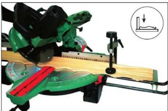
natural_image
Green and black saw cutting machine with a ruler, showing a close-up of a small surface detail (no text or symbols visible)Fig. 16
Fig. 13
natural_image
Green cutting machine with hands operating it, labeled parts 1 and 2 (no text or symbols on the machine itself)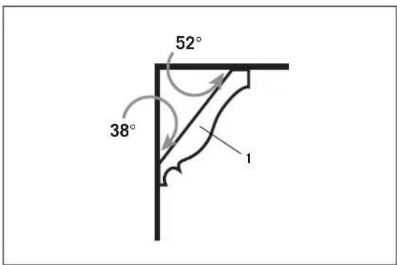
text_image
52° 38° 1Fig. 17
Fig. 14
text_image
Technical diagram of a green industrial machine with labeled parts 1 and 2, showing mechanical components and wiring.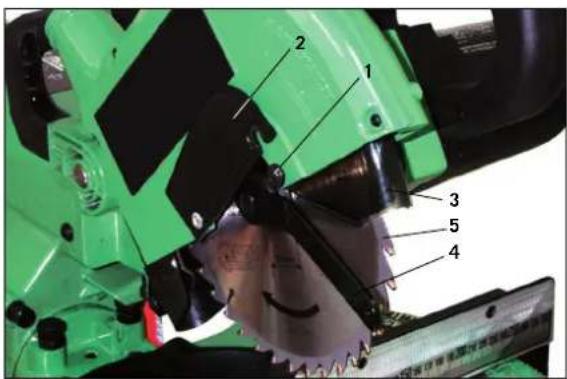
text_image
Labeled mechanical assembly diagram showing green cutting machine components with numbered partsFig. 18
Fig. 15
natural_image
Close-up of a green industrial machine tool with black components and a black arrow pointing to a component (no visible text or symbols)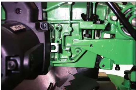
natural_image
Close-up of a green industrial machine component with visible parts and mounting holes (no text or symbols)Fig. 19
| DGBFINLGarantieAuf dieses Gerät gewähren wir Ihnen24 Monate Garantie1. Die Garantie erstreckt sich ausschließlich auf Material- oder Fabrika-tionsfehler. Schadhafte Teile werden kostenlos ersetzt, der Austausch ist kundenseitig vorzu- nehmen.Wir übernehmen nur Garantie für Original scheppach-Teile.2. Kein Garantieanspruch besteht bei: Transportschäden, Verschleißteilen, Schäden durch unsachgemäße Behandlung sowie Nicht-beachtung der Betriebs-anweisung, Ausfälle der elektrischen Anlage bei Nichtbeachtung der elek-trischen Vorschriften. VDE-Bestimmungen 0100, DIN 57113/ VDE 0113.3. Desweiteren können Garantieansprüche nur für Geräte geltend ge-macht werden, welche von dritten Personen nicht repariert wurden.Der Garantieschein hat nur Gültigkeit in Verbindung mit der Rechnung. | GuaranteeThis appliance is covered by a24 month’s guarantee1. The guarantee covers only material and con- struction faults. Faulty parts are replaced free of charge, customers must carry out replacement work.We guarantee only original scheppach parts.2. The guarantee does not cover: Transport damage, wearing parts, damage resulting from improper use or failure to observe operating instructions, electrical faults if electrical regulations are not observed.3. Guarantee claims are valid only if no repairs have been made by a third party.The warranty certificate is only valid with the invoice. | GarantieSur cet appareil, nous vous assurons24 mois de garantie1. La garantie ne prend effet que pour des défauts de matériel ou de fabrication. Les pièces défectueuses sont remplacées gratuït-ment, l’échange doit être accompli par le client.Nous n’assurons la garantie que pour les pièces scheppach d’origine.2. La garantie ne prend pas effet lors de:Avaries de transport, pièces d’usure, dommages résultants d’une mani-pulation erronée, ainsi que pour les détériorations résultant d’un non respect des consignes d’utilisation et d’une défectuosité des circuits électriques lors du non respect des consignes en vigueur.3. De plus, le droit à la garantie ne peut être sollicité que pour des appareils n’ayant pas fait l’objet de réparation par une tierce personne.Le certificat de garantie n’a d’effet que sur presentation de la facture. | GaranziaPer quest’apparecchio diamo una garanzia di 24 mesi1. La garanzia si estende esclusivamente ai difetti di materiale o di fabbrica. Le parti difettose saranno ricambiate gratuitamente, la sostituzione va effettuata da parte del cliente.Ci assumiamo la garanzia solo per parti originali scheppach.2. La garanzia non copre:Danni da trasporto, pezzi d’usura, danni derivati da uso improprio o dalla mancata osservazione delle istruzioni per l’uso, guasti dell’impianto elettrico dovuti all’inos-servanza delle norme sull’elettricità.3. La garanzia decade se vengono effettuate riparazioni da persone non autorizzate.Il certificato di garanzia è valido solo insieme alla fat-tura. | GarantieOp dit apparaat bieden wij U24 maanden garantie1. De garantie heeft alleen betrekking op materiaal-of fabricagefouten.Beschadigde onderdelen worden kostenlos ver-vangen. De vervanging wordt bij de klant door-gevoerd.Wij bieden alleen garan-tie op originele onderde-len van scheppach.2. Er kan geen aanspraak op garantie worden ge-maakt bij: Transport-schade, slijtende onder-delen, schade door ondeskundige behande-ling alsmede door het niet inachtnemen van de gebruiksaanwijzing, bij het uitvallen van de electrische installatie door het niet inachtnemen van de electrische voorschriften.3. Vervolgens kan er alleen aanspraak op garantie worden gemaakt, als het apparaat niet door derden werd gerepareerd.Deze garantieverklaring is alleen geldig in verbinding met de rekening. |
| HÄNDLER: DEALER: VENDEUR: RIVENDITORE: HANDELAAR: | Gerätetype: Appliance type: Type d'appareil: Tipo d'apparecchio: Type: |
| Gerätenummer: Serial number: Numéro de l'appareil: N. dell'apparecchio: Nummer: |
| KontrolleBei einer eventuellenReklamation senden Sie bitte diesen Kontrollzettel an Ihren Händler oder an uns. | Check slipIn case of any claim,please return this check slip to your dealer or to us. | Fiche de contrôleEn cas d'une réclamation éventuelle, retournez cette fiche de contrôle à votre vendeur ou à nous. | Biglietto di controlloIn caso di un reclamo eventuale, bisogna rispedire questo biglietto di controllo al rivenditore o a noi. | ControlestrookIn het geval van een eventuele reclamatie moeten wij u vragen, deze controle-strook aan de handelaar of aan ons terug te sturen. |
E Garantía
Esta máquina tiene