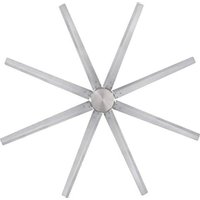
Widespan 7224940 - Fan WESTINGHOUSE - Free user manual and instructions
Find the device manual for free Widespan 7224940 WESTINGHOUSE in PDF.


| Product Type | High Volume Ceiling Fan |
| Brand | Westinghouse |
| Model | Widespan 7224940 |
| Blade Diameter | 254 cm (100 inches) |
| Intended Use | Large indoor spaces: factories, barns, farms, gyms, warehouses |
| Power Supply | 230 V ~ 50 Hz (European standard) |
| Maximum supported weight by outlet box | 22.7 kg (50 lb) |
| Minimum height from floor to blades | 3.05 m (10 ft) |
| Protection Rating | IP20 (indoor only) |
| Number of Speeds | 6 (from very slow to very fast) |
| Control Type | Wireless remote control with built-in receiver |
| Timer Function | Yes, adjustable from 1 to 8 hours |
| Recommended Switch | Double-pole switch with 3 mm contact opening |
| Compatible Dimmer Type | Only with model BF-5 (do not use with solid-state dimmer) |
| Lubrication | Permanent, no oil required |
| Maintenance and Cleaning | Soft brush or lint-free cloth; do not use water |
| Required Installation | By a qualified electrician only |
| Blade Material | Wood (varnished to resist discoloration) |
| Approximate Weight | Approximately 15-20 kg (depending on configuration) |
Frequently Asked Questions - Widespan 7224940 WESTINGHOUSE
User questions about Widespan 7224940 WESTINGHOUSE
0 question about this device. Answer the ones you know or ask your own.
Ask a new question about this device
Download the instructions for your Fan in PDF format for free! Find your manual Widespan 7224940 - WESTINGHOUSE and take your electronic device back in hand. On this page are published all the documents necessary for the use of your device. Widespan 7224940 by WESTINGHOUSE.
USER MANUAL Widespan 7224940 WESTINGHOUSE
natural_image
Line drawing of a six-pole ceiling fan with a top-mounted head and radial blades (no text or symbols)GB CEILING FAN
D DECKENVENTILATOR
F VENTILATEUR DE PLAFOND
I VENTILATORE DA SOFFITTO
NL PLAFONDVENTILATOR
E VENTILADOR DE TECHO
EST VENTILAATOR-LAEVALGUSTI
LV GRIESTU VENTILATORS
LT LUBU VENTILIATORIUS
SK STROPNÝ VENTILÁTOR
CZ STROPNÍ VENTILÁTOR
SLO STROPNI VENTILATOR
HR STROPNI VENTILATOR
H MENNYEZETI VENTILÁTOR
GAS WARNING: Do not use this fan in the same room at the same time as a gas or fuel burning fire, unless the flue has been tested under these conditions of use by a competent person.
SAFETY TIPS
READ AND SAVE THESE INSTRUCTIONS
WARNING: TO REDUCE THE RISK OF FIRE, ELECTRIC SHOCK, OR INJURY TO PERSONS, OBSERVE THE FOLLOWING:
- Proceed with caution. Read all instructions before beginning the installation.
- WARNING! This fan may be operated only with a 2-pole switch with a 3mm contact opening each.
- Only an authorized electrician should execute the installation.
- The installation height, i.e. the distance between the blades and the floor, should be at least 3.05 m.
- Make sure the fan is securely fastened at the ceiling.
- WARNING! To prevent injuries, make sure the blades are not bent and that there are no objects with in the area of rotation.
- WARNING: Do Not use this fan in the same room at the same time as a gas or fuel burning fire, unless the flue has been tested under these conditions of use by a competent person.
- This appliance can be used by children aged from 8 years and above and persons with reduced physical, sensory or mental capabilities or lack of experience and knowledge if they have been given supervision or instruction concerning use of the appliance in a safe way and understand the hazards involved. Children shall not play with the appliance. Cleaning and user maintenance shall not be made by children without supervision.
- Suitable for use indoors.
- Means for all poles disconnection having a contact separation that provide full disconnection under over voltage category III conditions must be incorporated in the fixed wiring in accordance with national wiring rules.
- IP20 The fan is designed for indoor use. It is not designed for installation in a bathroom or any damp area. Please ensure that the lamp does not come into contact with water.
- All set screws must be checked and re-tightened where necessary before installation.
- WARNING! To reduce the risk of fire or electric shock, do not use this fan with any solid state fan speed control device, or variable speed control. this fan should only be used with fan speed control part #: BF-5.
- Before you begin installing the fan and servicing or cleaning unit, switch power off at service panel and lock service disconnecting means to prevent power from being switched on accidentally. When the service disconnecting means cannot be locked, securely fasten a prominent warning device, such as a tag, to the service panel.
- Use this unit only in the manner intended by the manufacturer. If you have any questions, contact the manufacturer.
- After making the wire connections, gently push connections into outlet box with wire nuts pointing up. The wires should be spread apart with the grounded conductor and the equipment-grounding conductor on one side of the outlet box and ungrounded conductor on the other side of the outlet box.
- When cutting or drilling into wall or ceiling, do not damage electrical wiring and other hidden utilities.
- To reduce the risk of electric shock, or personal injury, mount to outlet box marked “acceptable for fan support of 22.7 Kg (50 lb.) or less” and use mounting screws provide with the outlet box and/or support directly from building structure. Most outlet boxes commonly used for the support of lighting fixtures are not acceptable for fan support and may need to be replaced. Consult a qualified electrician if in doubt.
-
This fan is designed for certain applications only. Westinghouse is not responsible for issues arising from modification or improper use of this product such as an application for which it was not designed. We strongly recommend that this product not be modified and/or used for any application other than that for which it was designed.
-
The Widespan 100In. High Volume Ceiling Fan is designed for large, high ceiling areas such as factories, barns, ranches, gyms, and warehouses.
- The warnings, cautions, and instructions in this manual cannot cover all possible conditions or situations that could occur. Exercise common sense and caution when using this tool. Always be aware of the environment and ensure that the tool is used in a safe and responsible manner. 2. WARNING! This fan may be operated only with a 2-pole switch with a 3mm contact opening each.
- Do not modify this product in any way. Unauthorized modification may impair the function and/or safety and could affect the life of the product. There are specific applications for which the product was designed.
- Use the right tool for the job. DO NOT attempt to force small equipment to do the work of larger industrial equipment. There are certain applications for which this equipment was designed. This product will be safer and do a better job at the capacity for which it was intended. DO NOT use this equipment for a purpose for which it was not intended.
- Inspect the work area before each use. Keep work area clean, dry, free of clutter, and well-lit. Cluttered, wet, or dark work areas can result in injury. Using the product in confined work areas may put you dangerously close to cutting tools and rotating parts.
- Do not use the product where there is a risk of causing a fire or an explosion; e.g., in the presence of flammable liquids, gases, or dust. The product can create sparks, which may ignite the flammable liquids, gases, or dust.
- Do not allow the product to come into contact with an electrical source. The tool without insulation and contact will cause electrical shock.
- Be aware of all power lines, electrical circuits, water pipes, and other mechanical hazards in your work area. Some of these hazards may be hidden from your view and may cause personal injury and/or property damage if contacted.
- Stay alert, watch what you are doing, and use common sense when operating the tool. Do not use the tool while you are tired or under the influence of drugs, alcohol, or medication. A moment of inattention while operating the tool may result in serious personal injury.
- Dress properly. Do not wear loose clothing, dangling objects, or jewelry. Keep your hair, clothing and gloves away from moving parts. Loose clothes, jewelry, or long hair can be caught in moving parts. Air vents on the tool often cover moving parts and should be avoided.
- Do not force the fan. Products are safer and do a better job when used in the manner for which they are designed. Plan your work and use the correct product for the job.
- Check for damaged parts before each use. Carefully check that the product will operate properly and perform its intended function. Replace damaged or worn parts immediately. Never operate the product with a damaged part.
- Do not use a product with a malfunctioning switch. Any power tool that cannot be controlled with the power switch is dangerous and must be repaired by an authorized service representative before using.
- Store the product when it is not in use. Store it in a dry, secure place out of the reach of children. Inspect the tool for good working condition prior to storage and before re-use.15. Use this unit only in the manner intended by the manufacturer. If you have any questions, contact the manufacturer.
- Use only accessories that are recommended by the manufacturer for use with your product. Accessories that may be suitable for one product may create a risk of injury when used with another tool. Never use an accessory that has a lower operating speed or operating pressure than the tool itself.
- Keep guards in place and in working order. Never operate the product without the guards in place.
- To reduce the risk of fire or electrical shock, do not expose fan to water or rain.
- Do not use fan near windows; rain and moisture may create an electrical hazard.
-
Do not alter fan's assembly.
-
If the power supply cord is damaged, contact your local service center or a qualified electrician to install an appropriate replacement cord to prevent any injury or damage.
- The appliance should not be used in locations where special conditions prevail such as the presence of a corrosive or explosive atmosphere (dust, vapor, gas).
- Do not place the fan near an open flame, cooking or heating appliance, or hot surface.
- Be sure fan is not making unusual sounds or movements.
- Be sure fan is switched off when unattended.
- Be sure not to loosen any of the fan's connections while maintaining your fan.
- Do not use cleaners that harm paints or plastics; i.e., bleach or ammonia
natural_image
Line drawing showing a printer box open and inserting an open circuit board with a hand interacting (no text or symbols)GB Unpack and inspect fan carefully to be certain all contents are included. Turn off power at fuse box to avoid possible electrical shock.
natural_image
Diagram of a bathtub with three circular arrows indicating cycle (no text or symbols)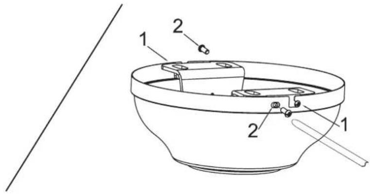
GB Remove the screws from the two mating holes (2) on the canopy. Loosen (do not remove) the screws in the mating slots (1) on the canopy. Rotate the mounting bracket and remove from the canopy.
GB According to the line art, drill two holes on each side of the supply mains for the expansion anchors. WARNING: The ceiling or structure the device is attached to must be strong enough to hold 100 kg/20 cm ^2 .
GB Drive the expansion anchors (1) into the holes. (Note: do not detach hex nut (2), spring washer (3) and metal washer (4) for this step).
natural_image
Technical diagram of a mechanical assembly with two cylindrical components and a separate section, showing alignment lines and dimension arrows (no text or labels)GB Tighten hex nut until feel the metal expansion anchor is not working loose.
natural_image
Technical diagram of a mechanical assembly with threaded components and a cross-section view (no text or labels)GB Remove the hex nut, spring washer, metal washer, keep them for next step usage.
natural_image
Technical line drawing of a mechanical bracket assembly with multiple cylindrical components and mounting holes (no text or symbols)GB Attach the ceiling bracket with the four expansion metal anchors of 10 mm diameter, washers and screws provided. Make sure the screws are properly tightened and the bracket is secure (not moving at all).
GB Remove clamp pin (2) and cross pin (1) from downrod. Loosen set screw in downrod ball (3) until ball moves easily up and down the downrod. Do not remove ground wire (4) from downrod ball. Slide downrod ball down, exposing cross pin (5). Do not remove ball completely. Remove cross pin and save for later use.
natural_image
Line drawing of a lamp with a base and top component (no text or symbols)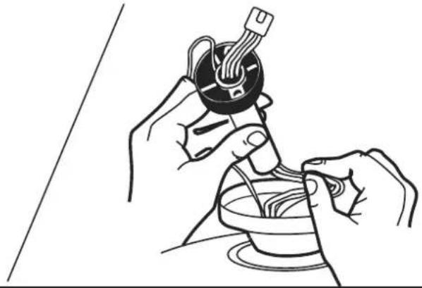
natural_image
Line drawing of hands assembling a mechanical component with wires (no text or symbols)GB Insert the downrod through the canopy and coupling cover. Carefully thread lead wires and plug though the downrod and ball assembly.
natural_image
Three-panel illustration showing hands using a tool to adjust a black object in a bowl, with no visible text or symbols.GB Re-install cross pin into downrod and slide downrod ball up until cross pin fits firmly into ball. Tighten set screw in ball.
GB Loosen set screws in downrod coupling (1). Insert downrod into downrod coupling. Make sure to align hole in downrod with the hole in coupling. Install yoke cross pin (2) through yoke and downrod. Insert clamp pin (3) into cross pin until it snaps into place. Tighten set screws (4) in coupling. Slide coupling cover (5) over coupling.
GB Carefully lift fan assembly onto mounting bracket. Rotate fan until notch on down rod ball (1) engages the ridge on the mounting bracket (2). This will allow for hands free wiring. Thread the metal safety cable (3) through the ceiling bracket and secure it by tightening the nut on the safety bolt (4).
D Die Ventilatoreinheit vorsichtig anheben und auf die Deckenplatte anbringen. Den Ventilator drehen, bis die Sicherungskugel (1) der unteren Stange in die Furche der Montagehalterung (2) einrastet. Dadurch wird eine freihändige Verkabelung ermöglicht. Das Metallsicherheitskabel (3) durch die Deckenhalterung führen und durch Anziehen der Mutter an der Sicherheitsschraube (4) feststellen.
F Avec précaution, soulevez l'assemblage de ventilateur jusqu'au support de montage. Faites tourner le ventilateur pour que l'encoche sous la bille de tige inférieure (1) s'engage dans le rebord sur le support de montage (2). Vous assurez ainsi un câblage mains libres. Filetez le câble de sécurité métallique (3) à travers le support de plafond et fixez-le en serrant l'écrou sur le boulon de sécurité (4).
Sollevare con cautela il gruppo del ventilatore sulla staffa di montaggio. Ruotare il ventilatore fino quando la tacca sulla sfera dell'asta inferiore (1) non si innesti sulla sporgenza della staffa di montaggio (2). In questo modo, il cablaggio potrà essere effettuato a mani libere. Infilare il cavo di sicurezza in metallo (3) attraverso la staffa del soffitto e fissarlo serrando il dado sul bullone di sicurezza (4).
NL Hef de ventilator voorzichtig op de montagebeugel. Draai de ventilator tot de inkeping op de neerwaartse stangkogel (1) in de nok aan de montagebeugel (2) grijpt. Dit maakt handsfree bedrading mogelijk. Steek de metalen veiligheidskabel (3) door de plafondbeugel en zet deze vast door de moer op de veiligheidsbout vast te draaien (4).
E Levante con cuidado el conjunto del ventilador hasta el soporte de montaje. Gire el ventilador hasta que la muesca en la bola de la barra (1) engrane en la ranura del soporte de montaje (2). De este modo, tendrá las dos manos libres para hacer el cableado. Enhebre el cable de metal de seguridad (3) a través del soporte de techo y asegúrelo apretando la tuerca del perno de seguridad (4).
P Levante com cuidado a ventoinha montada até ao suporte de montagem. Rode o ventilador até o entalhe na haste de acionamento (1) encaixar o rebordo no suporte de montagem (2). Isso permite mais liberdade às mão para ligação. Enrosque o cabo de segurança de metal (3) pelo suporte do teto e fixe-o apertando a porca no parafuso de segurança (4).
N Løft vifteenheten forsiktig inn på monteringsbraketten. Drei viften til hakket på den nedre stangkulen (1) griper inn i kanten på monteringsbeslaget (2). Dette vil gi rom for håndfri kabling. Før metallsikkerhetskabelen (3) gjennom takbeslaget og fest den ved å stramme mutteren på sikkerhetsbolten (4).
S Lyft försiktigt upp fläkten på monteringshållaren. Vrid fläkten tills dess att skåran på den nedre stavkulan (1) kommer i kontakt med kanten av monteringsfästet (2). Detta gör det möjligt att dra in ledningen utan att använda händerna. Trä metallskyddskabeln (3) genom takfästet och fäst den genom att dra åt muttern på säkerhetsskruven (4).
FIN Nosta tuuletinkokonaisuus varovasti kiinnittimeen. Kierrä tuuletinta, kunnes pallotangon (1) ura lovi kytkeytyy asennuspidikkeeseen (2). Se jälkeen voit vapaasti kytkeä johdot. Pujota metallinen turvakaapeli (3) kattopidikkeen läpi ja varmista se kiristämällä kiinnitysruuvin mutteria (4).
DK Forsigtigt løft ventilatorsamlingen op på monteringsholderen. Roter ventilatoren, indtil hakket på kuglen på den nedadgående stang (1) griber fat i monteringsbeslaget (2). Dette gør det nemmere at gennemføre ledningsføringen med hænderne. Sæt sikkerhedsmetalwiren (3) ind gennem monteringsbeslaget i loftet, og sæt det fast ved at stramme møtrikkerne på sikkerhedsbolten (4).
PL Ostrożnie podnieś zestaw wentylatora na wspornik. Obracaj wentylator, aż nacięcie na kulistej podstawie (1) pionowego pręta zaczepi się na występie wspornika montażowego (2). Umożliwi to zwolnienie rąk w celu przeprowadzenia okablowania. Przeciągnij metalowy kabel zabezpieczający (3) przez wspornik sufitowy i zamocuj go, dokręcając nakrętkę na śrubie zabezpieczającej (4).
RUS Аккуратно поднять вентилятор и установить его на кронштейне. Повернуть вентилятор таким образом, чтобы надрез на шарике нижнего стержня (1) зафиксировал конек на монтажном кронштейне (2). Это позволит освободить руки для выполнения электрических соединений. Пропустить металлический предохранительный трос (3) через потолочный кронштейн и закрепить его, затянув гайку на предохранительном болте (4).
UA Обережно підніміть вузол вентилятора до монтажного кронштейну. Обертайте вентилятор, поки виймка на кульці штока (1) не зачепиться за виступ на монтажному кронштейні (2). Це дозволить звільнити руки для виконання електричних з'єднань. Протягніть металевий запобіжний кабель (3) через стельовий кронштейн та зафіксуйте його, для цього затягніть гайку на запобіжному болті (4).
EST Töstke ettevaatlikult ventilaatori kooslus paigalduskronsteinile. Keerutage ventilaatorit, kuni sälk ventilaatori vardal (1) ühendub vaoga laekronsteinil (2). See võimaldab käed-vabad kaabeldust. Lükake metallist ohutuskaabel (3) läbi laekronsteini ja kinnitage see, pingutades kinnituspoldi (4) mutrit.
LV Uzmanīgi paceliet ventilatora sastāvdaļas uz piestiprināšanas kronšteina. Groziet ventilatoru, kamēr robs uz apakšējā stieņa bumbas (1) sakritis ar izcilni uz montāžas stiprinājuma (2). Tas ľaus savienot elektroinstalāciju, neturot ventilatoru ar rokām. Izvelciet metāla drošības kabeli (3) cauri griestu turētājam un piestipriniet to, pievelkot uzgriezni uz drošības bultskrūves (4).
LT Atsargiai uždėkite ventilatoriaus bloką ant tvirtinimo rėmo. Sukite ventilatorių, kol griovelis ant strypo rutulio (1) susijungs su briauna ant tvirtinimo rėmo (2). Taip atlaisvinsite rankas ir galėsite pravesti laidus. Perkiškite metalinį apsauginį kabelį (3) per lubinį laikiklj ir pritvirtinkite priverždami apsauginio varžto veržlę (4).
SK Opatrne zodvihnite zmontovaný ventilátor na montážny držiak. Otáčajte ventilátorom, kým zárez na guli predlžovacej tyče (1) nezapadne do drážky na montážnej konzole (2). Budete tak môč zapojiť káble bez použitia rúk. Prevlečte kovový bezpečnostný kábel (3) cez stropnú konzolu a zaistite ho dotiahnutím matice na bezpečnostnej skrutke (4).
CZ Opatrně vyzvedněte sestavu ventilátoru na nosný držák. Otáčejte ventilátorem, dokud zářez na kouli dolního táhl a (1) nezapadne na hřeben na montážní konzole (2). Uvolnite si tak ruce pro zapojení drátů. Protáhněte kovový bezpečnostní kabel (3) skrz stropní konzolu a zajistěte jej utažením matice na bezpečnostním šroubu (4).
SLO Previdno privzdignite sklop ventilatorja na stropno plošėo. Obračajte ventilator, dokler utor na krogelnem delu nosilne palice (1) ne zaskoči v rob na montažnem nosilcu (2). To bo omogočilo prostoročno izvedbo napeljave. Kovinski varnostni kabel (3) vstavite skozi stropni nosilec in ga pritrdite s privitjem matice na varnostni vijak (4).
HR Pažljivo podignite sklop ventilatora do ploče za pričvršćivanje. Rotirati ventilator dok žljeb na donjoj kugli šipke (1) ne zahvati brazdu na montažnom nosaču (2). To omogućuje postavljanje žica bez upotrebe ruku. Provući metalni sigurnosni kabel (3) kroz plafonski nosač i fiksirati ga pritezanjem sigurnosnog zavrtnja (4).
H Óvatosan emelje a ventilátoregységet a rögzítőkeretre. Fordítsa el a ventilátort addig, amíg a lefelé irányló rúd lezárásán (1) található bevágás egybeesik a tartókereten lévő (2) éllel. Igy kezei szabaddá válnak a szereléshez. Füzze át a fém biztonsági kábelt (3) a mennyezeti rögzítőderékszögön, és rögzítse a biztonsági csavar anyacsavarjának megszorításával (4).
BG Вдигнете вентилаторната единица внимателно и я поставете на таванната плочка. Завъртете вентилатора, докато жлебът на долния сферичен прът (1) не се фиксира в ръба на монтажната скоба (2). Това ще позволи си освободите ръцете за свързването. Прокарайте металния предпазен кабел (3) през тавана и го фиксирайте чрез затягане на гайката на обезопасителния болт (4).
RO D Rotiți ventilatorul până când crestătura de pe profilul tijei inferioare (1) se cuplează la bavura de pe suportul de fixare (2). Acest lucru va permite cablarea fără utilizarea maiinilor. Introduceți cablul metallic de siguranță (3) prin suportul tavanului și fixați-l prin strângerea piuliței pe șurubul de siguranță (4). e ventilator cu atentie si puneti-o pe placa de tavan.
GR Ανυψώστε προσεκτικά το συγκρότημα του ανεμιστήρα προς τη βάση στήριξης. Περιστρέψτε τον ανεμιστήρα μέχρι η εγκοπή στην κάθετη ράβδο με σφαιρική άρθρωση(1) να ασφαλίσει στη πάχη του βραχίονα στήριξης (2). Αυτό καθιστα εφικτή την ελεύθερη καλωδίωση. Περάστε το μεταλλικό καλώδιο ασφαλείας (3) μέσα από τον βραχίονα οροφής και ασφαλίστε το σφίγγοντας το παξιμάδι στον πείρο ασφαλείας (4).
TR Pervane takımını dikkatlice bağlantı plakasına doğru kaldırın. Vantilatörü, alt tom tutucudaki çentik (1) montaj desteğindeki (2) çıkıntıya oturuncaya kadar döndürün. Böylece eller serbest şekilde kablo bağlantısını yapabilirsiniz. Metal güvenlik kablosunu (3) tavan desteğinden geçirin ve emniyet civatası (4) üzerindeki somunu sikarak sabitleyin.
natural_image
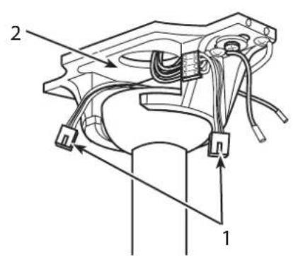
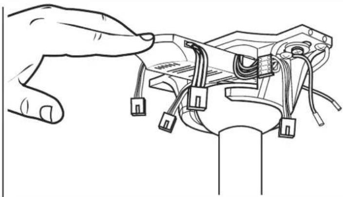
Line drawing of a hand inserting wires into a mechanical component (no text or symbols)GB After hanging fan onto the mounting bracket, make sure plug connectors from the ceiling fan and terminal block (1) are moved away from the space located above the downrod ball (2). Slide the remote receiver into the space above the downrod ball as shown.
GB While fan is hanging on bracket, plug 4-pole connector from the mounting bracket into the 4-pole plug connector from the remote receiver (1). Plug the 6-pole plug connector from the remote receiver into the 6-pole plug connector from the fan (2). Attach the ground wire (3) from the downrod to the mounting bracket.
GB The canopy has two mating slots (1) and two mating holes (2). Position both slots on canopy directly under and in line with two screws in the mounting bracket. Lift the canopy, allowing the two screws to slide into the mating slots. Rotate the canopy until both screws from the mounting bracket drop into the slot recesses. Tighten screws securely. Install two screws into the mating holes of the canopy and tighten to secure the canopy to the mounting bracket.
natural_image
Technical line drawing of a mechanical component with internal parts and mounting holes (no text or symbols)GB Install blades to the pre-installed blade flywheel using screws and nuts. See above drawing for reference.
GB
-
Note: Be sure the slide switch is pushed firmly to one side or the other. The fan will not operate with the slide switch in the middle.
-
To reverse the direction of the blades, slide the reverse switch (located in the cover of the transmitter) to the opposite side.
-
The slide switch controls the fan flow direction downward or upward.
-
Operation Turn on the power and check operation of fan. Speed settings for warm or cool weather depend on factors such as room size, ceiling height, number of fans and so on.
-
The slide switch controls direction, forward or reverse. Warm weather/down position - (Forward) Fan turns counterclockwise direction. A downward air flow creates a cooling effect as shown in illustration A. (S mark located above the battery) This allows you to set your air conditioner on a higher temperature setting without affecting your comfort. Cool weather/up position - (Reverse) Fan turns clockwise direction. An upward airflow moves warm air off the ceiling area as shown in illustration B. (W mark located above the battery) This allows you to set your heating unit on a lower setting without affecting your comfort.
NOTE: Turn off and wait for fan to stop before changing the setting of the forward/reverse slide switch.
D
-
Note : Assurez-vous que l'interrupteur coulissant est poussé fermement d'un côté ou de l'autre. Le ventilateur ne fonctionne pas avec l'interrupteur coulissant au milieu.
-
To reverse the direction of the blades, slide the reverse switch (located in the cover of the transmitter) to the opposite side.
-
The slide switch controls the fan flow direction downward or upward.
-
Operation Turn on the power and check operation of fan. Speed settings for warm or cool weather depend on factors such as room size, ceiling height, number of fans and so on.
-
The slide switch controls direction, forward or reverse. Warm weather/down position - (Forward) Fan turns counterclockwise direction. A downward air flow creates a cooling effect as shown in illustration A. (S mark located above the battery) This allows you to set your air conditioner on a higher temperature setting without affecting your comfort. Cool weather/up position - (Reverse) Fan turns clockwise direction. An upward airflow moves warm air off the ceiling area as shown in illustration B. (W mark located above the battery) This allows you to set your heating unit on a lower setting without affecting your comfort.
NOTE: Turn off and wait for fan to stop before changing the setting of the forward/reverse slide switch.
natural_image
Technical line drawing of a remote control device with internal components and a separate view (no text or symbols)GB Mount the transmitter holder onto the wall using screws provided. Place the transmitter into the holder.
GB Remote Control Operation
- Symbol from the transmitter- press and release reflects the fan ON/OFF function.
- The transmitter controls the fan speeds from the lowest speed to the highest speed. The remote control operates the fan speed as below: 1-lowest fan speed, 2-Med low fan speed, 3-Low fan speed; 4-Med fan speed; 5-Med high fan speed; 6-Highest fan speed.
- Ⓧ Operation duration time (1-8 hours setting).
GB Controlling more that one fan with remote control
-
The remote control has no memory function. When the fan is working after disconnecting the power supply, the original state cannot be restored.
-
The transmitter and receiver are matched at the factory. Please follow the point 4 for re-match when the match is failed.
-
With the matching process can be done by fan without the blades, the same transmitter can control another identical model ceiling fan.
-
When the transmitter and receiver are matched, the time key and the power on key on the transmitter panel must be pressed simultaneously within 5 seconds after the power button is connected.
-
The ceiling fan will make a buzzing sound twice. After it receives this, the fan has recognized the remote control and you can:
- Control this fan with the remote control.
- Re-match two ceiling fans with one remote control transmitter with the same process.
NOTE: To control two fans simultaneously, the installation distance between the two fans must not exceed 30 feet.
- Because of the fan's natural movement, some connections may become loose. Check the support connections, brackets, and blade attachments twice a year. Make sure they are secure.
- Clean your fan periodically to help maintain its new appearance over the years. Do not use water when cleaning. This could damage the motor, or the wood, or possibly cause electrical shock.
- Use only a soft brush or lint-free cloth to avoid scratching the finish. The plating is sealed with a lacquer coating to minimize discoloration or tarnishing.
- There is no need to oil your fan. The motor has permanently lubricated bearings.
- Maintain the fan by adopting a program of conscientious repair and maintenance in accordance.
- Maintain your fan. It is recommended that the general condition of any fan be examined before it is used. Keep your fan in good repair by adopting a program of conscientious repair and maintenance. Have necessary repairs made by qualified service personnel.
TROUBLESHOOTING GUIDE
If you have difficulty operating your new ceiling fan, it may be the result of incorrect assembly, installation, or wiring. In some cases, these installation errors may be mistaken for defects. If you experience any faults, please check this Trouble Shooting Chart. If a problem cannot be remedied, please consult with your authorized electrician and do not attempt any electrical repairs yourself.
TROUBLE
- Check main and branch circuit fuses or circuit breakers.
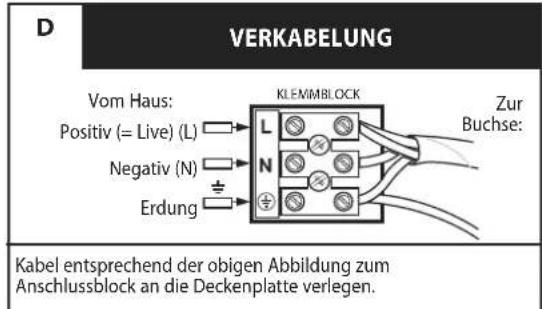
- Check terminal block connections as performed in step #8 of installation.
CAUTION: Make sure main power is turned off. - Make sure forward/reverse switch is firmly in up or down position. Fan will not operate when switch is in the middle.
-
If the fan still will not start, contact a qualified electrician. Do not attempt to troubleshoot internal electrical connections yourself.
-
If fan sounds noisy:
-
Check to make sure all screws in motor housing are snug (not over tightened).
- Check to make sure the screws, which attach the fan blade holder to the motor, are tight.
- Some fan motors are sensitive to signals from Solid State variable speed controls. DO NOT USE a Solid State variable speed control.
-
Allow "break-in" period of 24 hours. Most noises associated with a new fan will disappear after this period.
-
If fan wobbles:
All blades are weighed and grouped by weight. Natural woods vary in density, which could cause the fan to wobble even though all blades are weight-matched. The following procedures should eliminate most of the wobble. Check for wobble after each step.
1. Check that all blade holders are tightened securely to motor.
2. Make sure that canopy and mounting bracket are tightened securely to a fan rated electrical box or a ceiling joist.
3. Make sure that canopy and mounting bracket are tightened securely to ceiling joist.
4. If blade wobble is still noticeable, interchanging two adjacent (side by side) blades can redistribute the weight and possibly result in smoother operation.
5. Be sure ball to hanger bracket is locked in place. Remove canopy and adjust ball in hanger bracket.
Wartung
GB Meaning of crossed-out wheeled dustbin:
Do not dispose of electrical appliances as unsorted municipal waste, use separate collection facilities.
Contact you local government for information regarding the collection systems available.
If electrical appliances are disposed of in landfills or dumps, hazardous substances can leak into the groundwater and get into the food chain, damaging your health and well-being.
When replacing old appliances with new ones, the retailer is legally obligated to take back your old appliance for disposal at least free of charge.
Westinghouse Lighting Corporation
Krefelder Strasse 562
D-41066 Mönchengladbach / Germany

WESTINGHOUSE, and INNOVATION YOU CAN BE SURE OF
are trademarks of Westinghouse Electric Corporation.
Used under license by Westinghouse Lighting
All rights reserved.
Made in China



Brand : WESTINGHOUSE
Model : Widespan 7224940
Category : Fan