
TR60A - Folding tool Vevor - Free user manual and instructions
Find the device manual for free TR60A Vevor in PDF.

| Product Type | Manual Metal Bender |
| Brand | Vevor |
| Model | TR60A |
| Body Material | Cast Iron |
| Max Bending Width | 40 mm |
| Max Bending Thickness (mild steel) | 2 mm |
| Max Bending Thickness (aluminum) | 4 mm |
| Max Bending Angle | 360° |
| Bending Capacity | 20-gauge mild steel, 18-gauge aluminum, 20-gauge stainless steel |
| Included Accessories | Square tube die (3 pcs), round tube die (3 pcs), rotating handle, top handle, ball handle |
| Power Source | Manual (non-electric) |
| Main Functions | Bending pipes, flat bars, angle bars without heating or hammer |
| Safety | Wear safety glasses and gloves; keep work area clean and well-lit |
| Maintenance and Cleaning | Keep clean, lubricate moving parts, store in dry place |
| Spare Parts | M10 screws, nuts, upper and lower rollers, shafts, handles |
| Technical Support | www.vevor.com/support |
Frequently Asked Questions - TR60A Vevor
User questions about TR60A Vevor
0 question about this device. Answer the ones you know or ask your own.
Ask a new question about this device
Download the instructions for your Folding tool in PDF format for free! Find your manual TR60A - Vevor and take your electronic device back in hand. On this page are published all the documents necessary for the use of your device. TR60A by Vevor.
USER MANUAL TR60A Vevor
Technical Support and E-Warranty Certificate www.vevor.com/support
BENDER
MODEL: TR60A
We continue to be committed to provide you tools with competitive price. "Save Half", "Half Price" or any other similar expressions used by us only rep estimate of savings you might benefit from buying certain tools with us compared top brands and does not necessarily mean to cover all categories of tools offered are kindly reminded to verify carefully when you are placing an order with us actually saving half in comparison with the top major brands.
VEVOR®
TOUGH TOOLS, HALF PRICE
BENDER
natural_image
Technical line drawing of a mechanical clamp or bracket device with internal components and a handle (no text or symbols)TR60A
NEED HELP? CONTACT US!
Have product questions? Need technical support? Please feel from contact us:
Technical Support and E-Warranty Certificate www.vevor.com/support
This is the original instruction, please read all manual instruction carefully before operating. VEVOR reserves a clear interpretation user manual. The appearance of the product shall be subject to product you received. Please forgive us that we won't inform your there are any technology or software updates on our product.
PRODUCT PROFILE
The metal shrinker stretcher is designed to handle most of our automotive metal-shaping jobs. It features powerful steel jaws that can curve or angle 16 gauge aluminum, 18 gauge mild steel, 20 gauge stainless steel. Compound leverage allows effortless forming without making relief cuts, heating, or hammer-forming. The cast iron body can be utilized for a long service life.
IMPORTANT SAFEGUARDS

Read the instruction manual.

Warning- Be sure to wear eye protectors when using this product protectors when using this product.

Warning-Be sure to wear gloves when using this product.
WARNING: When using tool, basic safety precautions should always be follow to reduce the risk of personal injury and damage.
Read all instructions before using this tool!
- Keep work area clean. cluttered areas invite injuries.
- Consider work area conditions. don't use in damp, wet, or poorly location. expose to rain. keep work area wel lit.
- Keep children away. all children should be kept away from the work area let them handle machine.
- Store idle equipment. when not in use, tool should be locked up in a dr to inhibit rust. if possible, store in an area out of reach of children.
- Don't force the machine or tool. it will do the job better and more safely rate for which it was intended.
- Use the right tool. don't force a small tool or attachment to do the work larger industrial tool, don't use a tool for a purpose for which it was not int
- Dress properly. don't wear loose clothing or jewelry. they can be caught i moving parts. protective gloves and non-skid footwear are recommended when
working. wear restrictive hair covering to contain long hair, preventing it from getting caught in machinery.
- Use eye and ear protection. use a full-face mask if the work you're doing produces metal filings, dust or wood chips. goggles are acceptable in other situations. wear a clean dust mask if the work creates a lot of fine or coarse when operating for extended periods of time, use approved ear protection.
- Secure work. use clamps or a vise to hold the work if possible. it's safe using your hands and it frees both hands to operate the tool.
- Don't overreach. keep proper footing and balance at all time.
- Maintain tools with care. keep tools sharp and clean for better and safer performance. follow instructions for lubricating and changing accessories. Keep handles dry, clean, and free from oil and grease.
- Stay alert.watch what you are doing, use common sense. don't operate a tool when you are tired.
- Check damaged parts. before using any tool, any part that appears damage should be carefully checked to determine that it will operate properly and per it's intended function. check for alignment of moving parts, binding of moving breakage of parts, mounting, and other conditions that may affect it's operation. any part that is damaged should be properly repaired or the instruction manual.
- Replacement parts and accessories. when servicing, use only identical replacement parts. only use accessories intended for use with this tool.
- Do not operate tool if under the influence of alcohol or drugs.read warni labels on prescriptions to determine if your judgment or reflexes are impaired taking drugs. if there is any doubt, do not operate machine.
SPECIFICATIONS
| Model | TR60A |
| Maximum bending width | 40mm |
| Maximum bending thickness | Low carbon steel: 2mm; Aluminum: 4 |
| Maximum bending angle | 360° |
ACCESSORY
- Square tube moldX1 set (3pcs)
- Round tube moldX1 set (3pcs)
- Rotary Handle X 1 pcs
- Upper handleX1 pcs
- Handle ballX1 pcs
SPECIFICATIONS
| Material | Size | Minimum Radius |
Flats  | 1 1/4" | 10" |
C Channel  | 1 X2" | 60" |
Pipe Tube  | 1 1/2" | 20" |
Round Tube  | 1/4" to 2" | According To Material |
Square Tube  | 2" | According To Material |
Rect. Tube  | 1 X2" | 60" |
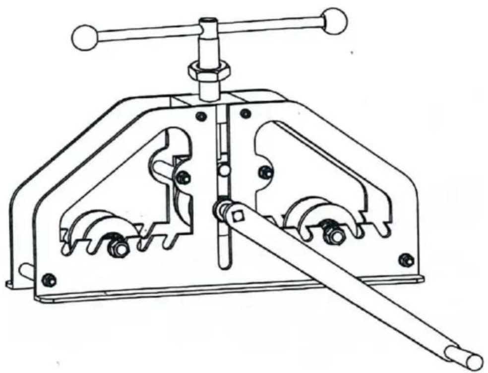
ASSEMBLE
- Fix the product on the workbench with 4 M10X30 screws and 4 M10 nut length of the screws can be adjusted according to the thickness of the work
The product does not come standard with M10X30 screws and M10 nuts.
- Thread the (12) rotary handle through the (13) lead screw, and then insta (11) handle ball onto the (12) rotary handle
- Install the (26) crane into (24), loosen the (25) pin on the (26) crane be installation, and tighten the (25) pin on the (26) crane after installation.
Screw fixing hole X 4
OPERATION
1. WORKING
Put two down roller(35) into frame's slot(6) symmetrically, turn lead screw(13), make upper roller(19) up to right deposition. Put into workpiece and clamp. E handle(28) turn crank clockwise and anticlockwise. Clamp workpiece again and turn crank again,
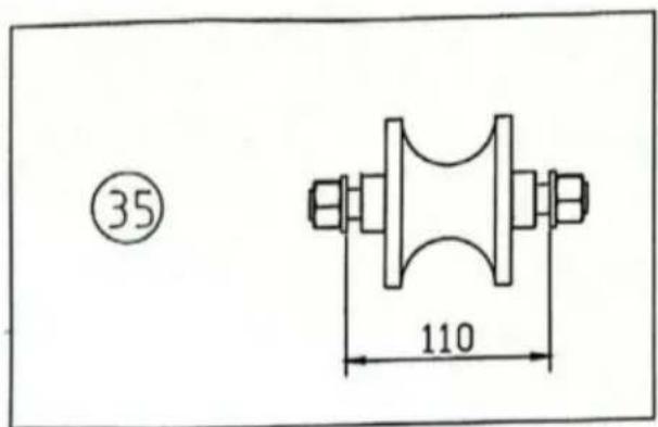
According to requirement, choose the center distance for two symmetrical dow roller(35). Reduce center distance when bending to bend out required size.
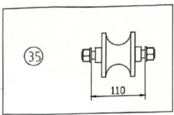
2. Change roller
Take down nut (4), get washer (3), knot (31) down. Take down roller (32) change for required roller. Then assemble the spare part.
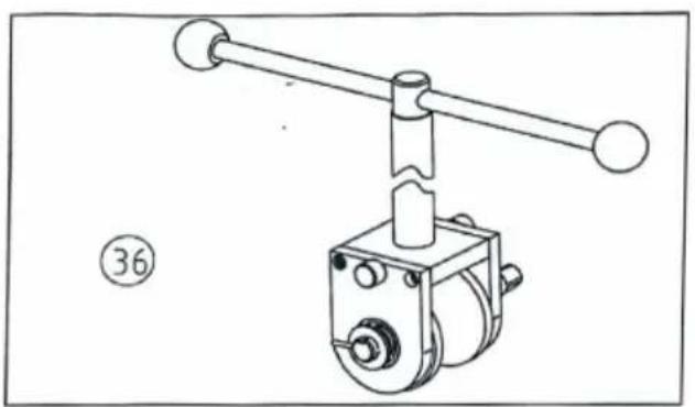
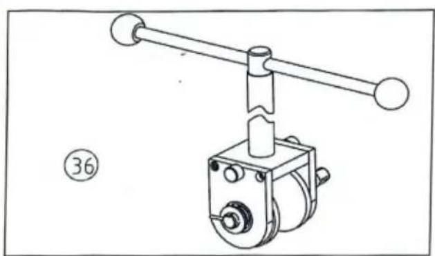
Take down SCREW (5), get upper roller (36) down. Take upper axis (24) out upper roller (19) down, change for required roller. Plug into upper axis (24) into pin(24). Then assemble back to rack.
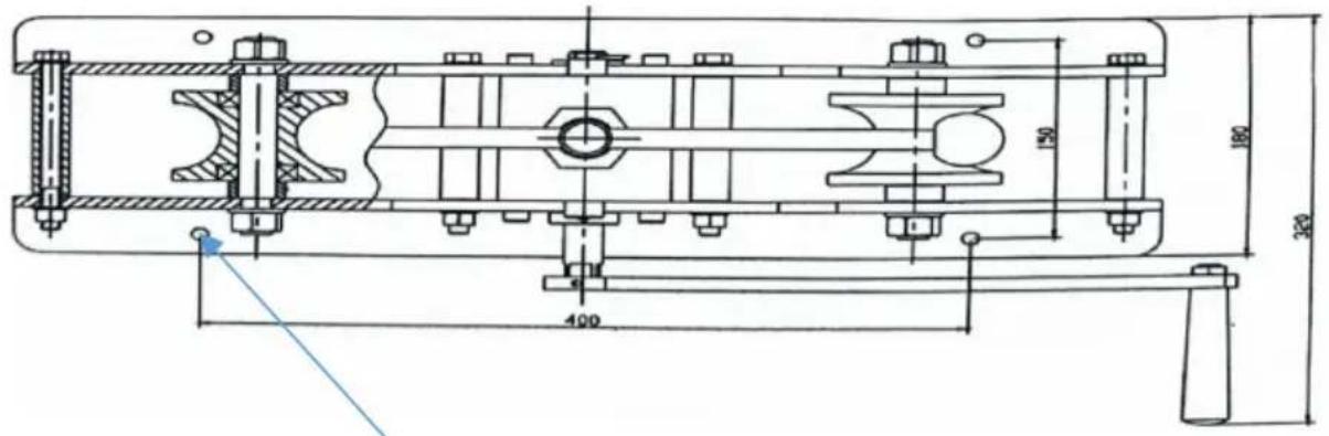
BREAKDOWN AND PARTS

natural_image
Technical line drawing of a mechanical device with lever and base mount (no text or symbols)| part No. | Description | Part No. | Description |
| 1 | WASHER | 21 | LOCATING BUSH |
| 2 | BOLT | 22 | SCREW |
| 3 | WASHER | 23 | PIN |
| 4 | NUT | 24 | UPPER ROLLER AXIS |
| 5 | SCREW | 25 | PIN |
| 6 | FRAME | 26 | CRANK |
| 7 | WASHER | 27 | SCREW |
| 8 | SCREW | 28 | HANDLE |
| 9 | LEADING AXIS | 29 | THIN NUT |
| 10 | BOARD | 30 | NUT |
| 11 | HANDLE BALL | 31 | KNOT |
| 12 | ROTARY HANDLE | 32 | ROLLER |
| 13 | LEAD SCREW | 33 | DOWN AXIS |
| 14 | TRANSVERSE BOARD | 34 | BOLT KNOT |
| 15 | KNOT | 35 | DOWN ROLLER |
| 16 | BEARING | 36 | UPPER ROLLER |
| 17 | BOLT | ||
| 18 | BEARING | ||
| 19 | ROLLER | ||
| 20 | UPPER BOARD |
PARTS LIST
Note: This manual is only for your reference. Owing to the continuous improvement of the machine, changes may be made at any time without obli on notice.
Manufacturer: Shanghaimuxinmuyeyouxiangongsi
Address: Shuangchenglu 803nong11hao1602A-1609shi, baoshanqu, shanghai 200000 CN.
Imported to AUS: SIHAO PTY LTD. 1 ROKEVA STREETEASTWOOD NSW 2 Australia
Imported to USA: Sanven Technology Ltd. Suite 250, 9166 Anaheim Place, Rancho Cucamonga, CA 91730
| EC | REP |
E-CrossStu GmbH
Mainzer Landstr.69, 60329 Frankfurt am Main
| UK | REP |
YH CONSULTING LIMITED.
C/O YH Consulting Limited Office 147, Centurion House, London Road, Staines-upon-Thames, Surrey TW18 4AX
VEVOR®
TOUGH TOOLS, HALF PRICE
Technical Support and E-Warranty Certificate
www.vevor.com/support
VEVOR®
TOUGH TOOLS, HALF PRICE
natural_image
Technical line drawing of a mechanical clamp or bracket device with internal components and a handle (no text or symbols)TR60A
BESOIN D'AIDE? CONTACTEZ-NOUS!
natural_image
Technical line drawing of a mechanical device with lever and base (no text or symbols)| Numéro de pièce | Description | Numéro de pièce | |
| 1 | RONDELLE | 21 | LOCALISATION DE LA BUSE |
| 2 | BOULON | 22 | VIS |
| 3 | RONDELLE | 23 | ÉPINGLE |
| 4 | NOIX | 24 | AXE DU ROULEAU SUPÉRIEUR |
| 5 | VIS | 25 | ÉPINGLE |
| 6 | CADRE | 26 | MANIVELLE |
| 7 | RONDELLE | 27 | VIS |
| 8 | VIS | 28 | POIGNÉE |
| 9 ÉCROU | MIXE DIRECTEUR | 29 | |
| 10 | CONSEIL | 30 | NOIX |
| 11 | POIGNÉE DE BALLE | 31 | NOEUD |
| 12 | ROTATIF POIGNÉE | 32 | ROULEAU |
| 13 | VIS MÈRE | 33 | AXE DESCENDANT |
| 14 | TRANSVERSAL CONSEIL | 34 | NŒUD DE BOULON |
| 15 | NOEUD | 35 | ROULEAU DESCENDANT |
| 16 | PALIER | 36 | ROULEAU SUPÉRIEUR |
| 17 | BOULON | ||
| 18 | PALIER | ||
| 19 | ROULEAU | ||
| 20 | PLANCHE SUPERIEURE |
LISTE DES PIÈCES
A/S YH Consulting Limited Bureau 147, Centurion
Maison, London Road, Staines-upon-Thames, Surrey, TW18 4AX
VEVOR®
TOUGH TOOLS, HALF PRICE
natural_image
Technical line drawing of a mechanical clamp or bracket device with internal components and a handle (no text or symbols)TR60A


natural_image
Technical line drawing of a mechanical device with lever and base (no text or symbols)| Teile-No | Beschreibung | Teile-No | Beschreibung |
| 1 | WASCHMASCHINE | 21 | POSITIONSBUCHSE |
| 2 | BOLZEN | 22 | SCHRAUBEN |
| 3 | WASCHMASCHINE | 23 | STIFT |
| 4 | NUSS | 24 | OBERE ROLLENACHSE |
| 5 | SCHRAUBEN | 25 | STIFT |
| 6 | RAHMEN | 26 | KURBEL |
| 7 | WASCHMASCHINE | 27 | SCHRAUBEN |
| 8 | SCHRAUBEN | 28 | HANDHABEN |
| 9 | FÜHRENDE ACHSE | 29 | DÜNNE MUTTER |
| 10 | PLANKE | 30 | NUSS |
| 11 | GRIFFBALL | 31 | KNOTEN |
| 12 | ROTIEREND HANDHABEN | 32 | ROLLE |
| 13 | Leitspindel | 33 | Abwärtsachse |
| 14 | QUER PLANKE | 34 | Bolzenknoten |
| 15 | KNOTEN | 35 | ABWÄRTSWALZE |
| 16 | LAGER | 36 | OBERE WALZE |
| 17 | BOLZEN | ||
| 18 | LAGER | ||
| 19 | ROLLE | ||
| 20 | OBERES BRETT |
TEILELISTE
C/O YH Consulting Limited Office 147, Centurion
Haus, London Road, Staines-upon-Thames, Surrey, TW18 4AX
VEVOR®
TOUGH TOOLS, HALF PRICE
www.vevor.com/support
VEVOR®
TOUGH TOOLS, HALF PRICE
natural_image
Technical line drawing of a mechanical clamp or bracket device with internal components and a handle (no text or symbols)TR60A


natural_image
Technical line drawing of a mechanical device with lever and base (no text or symbols)| parte n. | Descrizione | Numero parte | Descrizione |
| 1 | RONDELLA | 21 | LOCALIZZAZIONE DEL BUSH |
| 2 | BULLONE | 22 | VITE |
| 3 | RONDELLA | 23 | SPILLO |
| 4 | NOCE | 24 | ASSE RULLO SUPERIORE |
| 5 | VITE | 25 | SPILLO |
| 6 | TELAIO | 26 | MANOVELLA |
| 7 | RONDELLA | 27 | VITE |
| 8 | VITE | 28 | MANIGLIA |
| 9 | ASSE PRINCIPALE | 29 | DADO SOTTILE |
| 10 | ASSE | 30 | NOCE |
| 11 | PALLA MANICO | 31 | NODO |
| 12 | ROTANTE MANIGLIA | 32 | RULLO |
| 13 | VITE MADRE | 33 | ASSE VERSO IL BASSO |
| 14 | TRASVERSALE ASSE | 34 | NODO A BULLONE |
| 15 | NODO | 35 | RULLO GIÙ |
| 16 | CUSCINETTO | 36 | RULLO SUPERIORE |
| 17 | BULLONE | ||
| 18 | CUSCINETTO | ||
| 19 | RULLO | ||
| 20 | TAVOLA SUPERIORE |
ELENCO DELLE PARTI
Importato in AUS: SIHAO PTY LTD. 1 ROKEVA STREETEASTWOOD NSW 2122 Australia
Importato negli USA: Sanven Technology Ltd. Suite 250, 9166 Anaheim Place, Rancho Cucamonga, CA 91730
C/O YH Consulting Limited Ufficio 147, Centurion
Casa, London Road, Staines-upon-Thames, Surrey, TW18 4AX
VEVOR®
TOUGH TOOLS, HALF PRICE
elettronica www.vevor.com/support
VEVOR®
TOUGH TOOLS, HALF PRICE
natural_image
Technical line drawing of a mechanical clamp or bracket device with internal components and a handle (no text or symbols)TR60A


natural_image
Technical line drawing of a mechanical device with lever and base (no text or symbols)Casa, London Road, Staines-upon-Thames, Surrey, TW18 4AX
VEVOR®
TOUGH TOOLS, HALF PRICE
natural_image
Technical line drawing of a mechanical clamp or bracket device with internal components and a handle (no text or symbols)TR60A
POTRZEBUJESZ POMOCY? SKONTAKTUJ SIĘ Z NAMI!


natural_image
Technical line drawing of a mechanical device with lever and base (no text or symbols)| część nr. | Opis | Numer części. | Opis |
| 1 | PRALKA | 21 | LOKALIZACJA KRZASZCZU |
| 2 | ŚRUBA | 22 | ŚRUBA |
| 3 | PRALKA | 23 | SZPILKA |
| 4 | NAKRETKA | 24 | OŚ GÓRNEGO WAŁKA |
| 5 | ŚRUBA | 25 | SZPILKA |
| RAMA | 26 | KORBA6 | |
| 7 | PRALKA | 27 | ŚRUBA |
| 8 | ŚRUBA | 28 | UCHWYT |
| 9 | OŚ GŁÓWNA | 29 | CIENKA ORZECHÓWKA |
| 10 | TABLICA | 30 | NAKRETKA |
| 11 | RĄCZENIE PIŁKI | 31 | WEŻEŁ |
| 12 | OBROTOWY UCHWYT | 32 | WAŁEK |
| 13 | ŚRUBA OŁOWIOWA | 33 | OŚ DÓŁ |
| 14 | POPRZECZNY TABLICA | 34 | WEŻEŁ ŚRUBOWY |
| 15 | WEŻEŁ | 35 | WAŁEK DÓŁ |
| 16 | ŁOŻYSKO | 36 | WAŁEK GÓRNY |
| 17 | ŚRUBA | ||
| 18 | ŁOŻYSKO | ||
| 19 | WAŁEK | ||
| 20 | GÓRNA DESKA |
LISTA CZĘŚCI
C/O YH Consulting Limited Biuro 147, Centurion Dom, London Road, Staines-upon-Thames, Surrey, TW18 4AX
VEVOR®
TOUGH TOOLS, HALF PRICE
natural_image
Technical line drawing of a mechanical clamp or bracket device with internal components and a handle (no text or symbols)TR60A
HULP NODIG? NEEM CONTACT MET ONS OP!
Schroefbevestigingsgat X 4
WERKING
1. WERKEN


natural_image
Technical line drawing of a mechanical device with lever and base (no text or symbols)| Onderdeelnr. | Beschrijving | Onderdeelnr. | |
| 1 | WASMACHINE | 21 | PLAATSING VAN BUSH |
| 2 | BOUT | 22 | SCHROEF |
| 3 | WASMACHINE | 23 | PIN |
| 4 | MOER | 24 | BOVENSTE ROLLENAS |
| 5 | SCHROEF | 25 | PIN |
| KADER | 26 | KRUK6 | |
| 7 | WASMACHINE | 27 | SCHROEF |
| 8 | SCHROEF | 28 | HENDEL |
| 9 | LEIDENDE AS | 29 | DUNNE MOER |
| 10 | BORD | 30 | MOER |
| 11 | HANDLE BAL | 31 | KNOOP |
| 12 | ROTATIEF HENDEL | 32 | ROL |
| 13 | Loodschroef | 33 | OMLAAG-AS |
| 14 | TRANSVERSAAL BORD | 34 | SCHROEF KNOOP |
| 15 | KNOOP NEERWAARTSE5 ROL | ||
| 16 | HANDELSWIJZE | 36 | BOVENSTE ROL |
| 17 | BOUT | ||
| 18 | HANDELSWIJZE | ||
| 19 | ROL | ||
| 20 | BOVENSTE BOORD | ||
ONDERDELENLIJST
C/O YH Consulting Limited Kantoor 147, Centurion
Huis, London Road, Staines-upon-Thames, Surrey, TW18 4AX
VEVOR®
TOUGH TOOLS, HALF PRICE
garantiecertificaat www.vevor.com/support
VEVOR®
TOUGH TOOLS, HALF PRICE
natural_image
Technical line drawing of a mechanical clamp or bracket device with internal components and a handle (no text or symbols)TR60A
BEHÖVER HJÄLP? KONTAKTA OSS!
Skruva fästhål X 4
DRIFT
1. ARBETA


natural_image
Technical line drawing of a mechanical device with lever and base (no text or symbols)| del nr. | Beskrivning | Delnr. | Beskrivning |
| 1 | BRUCKOR | 21 | PLACERING BUSH |
| 2 | BULT | 22 | SKRUVA |
| 3 | BRUCKOR | 23 | STIFT |
| 4 | MUTTER | 24 | ÖVRE RULLAXEL |
| 5 | SKRUVA | 25 | STIFT |
| 6 | RAM | 26 | VEV |
| 7 | BRUCKOR | 27 | SKRUVA |
| 8 | SKRUVA | 28 | HANTERA |
| LEDANDE AXEL | 29 | TUNN NÖTTER9 | |
| 10 | STYRELSE | 30 | MUTTER |
| 11 | HANTERA BOLLEN | 31 | KNUT |
| 12 | ROTERANDE HANTERA | 32 | ROLLER |
| 13 | BLYSKRUV | 33 | NER AXEL |
| 14 | TRANSVERS STYRELSE | 34 | BOLTKNUT |
| 15 | KNUT | 35 | NEDRULLARE |
| 16 | LAGER | 36 | ÖVRE RULLE |
| 17 | BULT | ||
| 18 | LAGER | ||
| 19 | ROLLER | ||
| 20 | ÖVERSTYRELSE |
DELLISTA
C/O YH Consulting Limited Office 147, Centurion
House, London Road, Staines-upon-Thames, Surrey, TW18 4AX
VEVOR®
TOUGH TOOLS, HALF PRICE
www.vevor.com/support


