DN-100E - Welding machine Vevor - Free user manual and instructions
Find the device manual for free DN-100E Vevor in PDF.

User questions about DN-100E Vevor
0 question about this device. Answer the ones you know or ask your own.
Ask a new question about this device
Download the instructions for your Welding machine in PDF format for free! Find your manual DN-100E - Vevor and take your electronic device back in hand. On this page are published all the documents necessary for the use of your device. DN-100E by Vevor.
USER MANUAL DN-100E Vevor
Technical Support and E-Warranty Certificate www.vevor.com/support
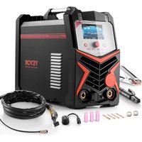
SPOT WELDER
MODEL: DN-100E
We continue to be committed to provide you tools with competitive price. "Save Half", "Half Price" or any other similar expressions used by us only repressor estimate of savings you might benefit from buying certain tools with us compared to top brands and does not necessarily mean to cover all categories of tools offered by are kindly reminded to verify carefully when you are placing an order with us if you actually saving half in comparison with the top major brands.
VEVOR®
TOUGH TOOLS, HALF PRICE
SPOT WELDER
MODEL:DN-100E

natural_image
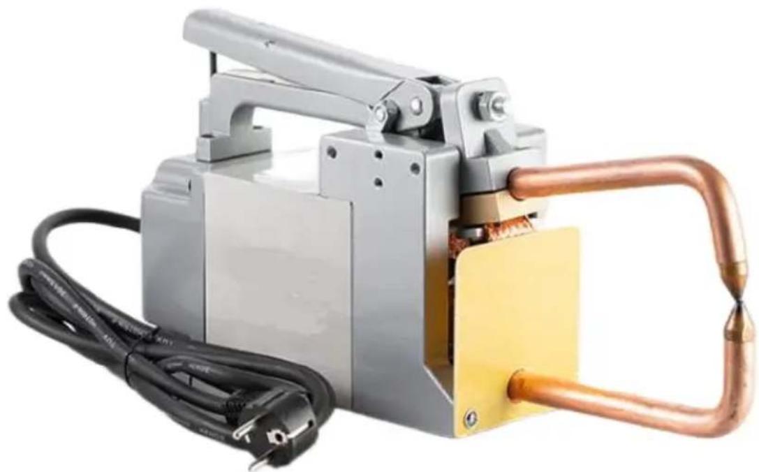
Industrial electrical tool with copper pipe and yellow base, connected to black and white cables (no visible text or symbols)NEED HELP? CONTACT US!
Have product questions? Need technical support? Please feel free contact us:
Technical Support and E-Warranty Certificate www.vevor.com/support
This is the original instruction, please read all manual instructions carefully before operating. VEVOR reserves a clear interpretation of user manual. The appearance of the product shall be subject to the product you received. Please forgive us that we won't inform you there are any technology or software updates on our product.
 | Warning-To reduce the risk of injury, user must read instructi manual carefully. |
 | CORRECT DISPOSALThis product is subject to the provision of European Directive 2012/19/EC. The symbol showing a wheelie bin crossed through indicates that the product requires separate refuse collection in European Union. This applies to the product and all accessor marked with this symbol. Products marked as such may not be discarded with normal domestic waste, but must be taken to collection point for recycling electrical and electronic devices |
SECTION 1- SAFETY PRECAUTIONS - READ BEFORE USIN
Protect yourself and others from injury — read and follow these precautions.
1-1. Symbol Usage
ANGER! -Indicates a hazardous situation which, if not avoided, will result in death or serious injury. The possible hazards are shown in the adjoining symbols or explained in the text.
Indicates a hazardous situation which, if not avoided, could result in death or serious injury. The possible hazards are shown in the adjoining symbols or explained in the text.
NOTICE -Indicates statements not related to personal injury.

Indicates special instructions.
natural_image
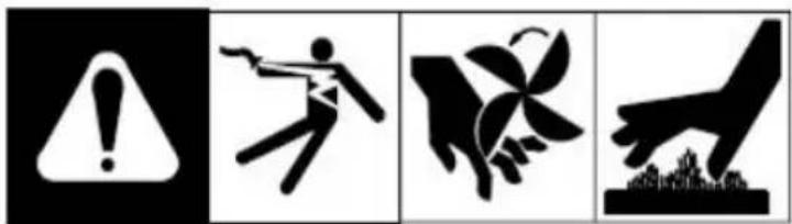
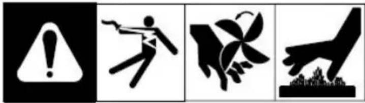
Four black-and-white pictograms: warning sign, falling figure, hand holding leaf, and hand reaching upward (no text or symbols)This group of symbols means Warning! Watch Out! ELECTRIC SHOCK, MOVING PARTS, and HOT PARTS hazards. Consult symbols and related instructions below for necessary actions to avoid the hazards.
1-2. Resistance Spot Welding Hazards

The symbols shown below are used throughout this manual to call attention to and identify possible hazards. When you see the symbol, watch out, and follow the related instructions to avoid the hazard. The safety information given below is only a summary of the more complete safety information found in the Safety Standards listed in Section 1-5. Read and follow Safety Standards.
Only qualified persons should install, operate, maintain, and repair this unit.
During operation, keep everybody, especially children, away.
- SPOT WELDING can cause fire or explosion.
Sparks can fly off from the welding arc. The flying sparks, hot workpiece, and hot equipment can cause fires and burns.
Accidental contact of electrode to metal objects can cause sparks, explosion, overheating, or fire. Check and be sure the area is safe before doing any welding.
- Remove all flammables within 35 ft (10.7 m) of the weld. If this is not possible tightly cover them with approved covers.
- Do not spot weld where flying sparks can strike flammable material.
- Protect yourself and others from flying sparks and hot metal.
- Be alert that welding sparks can easily go through small cracks and openings adjacent areas.
- Watch for fire, and keep a fire extinguisher nearby.
- Do not weld on closed containers such as tanks, drums, or pipes, unless they are properly prepared according to AWS F4.1 (see Safety Standards).
- Do not weld where the atmosphere may contain flammable dust, gas, or liquid vapors (such as gasoline).
- Remove any combustibles, such as a butane lighter or matches, from your person before doing any welding.
- After completion of work, inspect area to ensure it is free of sparks, glowing embers, and flames.
- Do not exceed the equipment rated capacity.
- Use only correct fuses or circuit breakers. Do not oversize or bypass them.
- Follow requirements in OSHA 1910.252 (a) (2) (iv) and NFPA 51B for hot work and have a fire watcher and extinguisher nearby.
• ELECTRIC SHOCK can kill.
Touching live electrical parts can cause fatal shocks or severe burns. The input power circuit and machine internal circuits are also live when power is on. Incorrectly installed or improperly grounded equipment is a hazard.
- Do not touch live electrical parts.
- Wear dry, hole-free insulating gloves and body protection.
- Additional safety precautions are required when any of the following electrically hazardous conditions are present: in damp locations or while wearing wet clothing on metal structures such as floors, gratings, or scaffolds; when in cramped positions such as sitting, kneeling, or lying; or when there is a high risk of unavoidable or accidental contact with the workpiece or ground. For these conditions, see ANSI Z49.1 listed in Safety Standards. And, do not work alone!
- Disconnect input power before installing or servicing this equipment. Lockout / tagout input power according to OSHA 29 CFR 1910.147 (see Safety Standards).
- Properly install and ground this equipment according to this manual and national, state, and local codes.
- Always verify the supply ground - check and be sure that input power cord ground wire is properly connected to ground terminal in disconnect box or that cord plug is connected to a properly grounded receptacle outlet.
- When making input connections, attach the grounding conductor first - double - check connections.
- Keep cords dry, free of oil and grease, and protected from hot metal and sparks.
- Frequently inspect input power cord and ground conductor for damage or bare wiring-replace immediately if damaged-bare wiring can kill. Check ground conductor for continuity.
- Turn off all equipment when not in use.
- For water-cooled equipment, check and repair or replace any leaking hoses or fittings. Do not use any electrical equipment if you are wet or in a wet area.
- Use only well-maintained equipment. Repair or replace damaged parts at once.
-
Wear a safety harness if working above floor level.
-
Keep all panels, covers, and guards securely in place.
- FLYING SPARKS can injure.
Very often sparks fly off from the joint area.
- Wear approved face shield or safety goggles with side shields.
- Wear protective garments such as oil-free, flame-resistant leather gloves, heavy shirt, cuffless trousers, high shoes, and a cap.
Synthetic material usually does not provide such protection.
- Protect others in nearby areas by using approved flame-resistant or noncombustiblefire curtains or shields. Have all nearby persons wear safety glasses with side shields.
• HOT PARTS can burn.
- Do not touch hot parts bare handed.
- Allow cooling period before working on equipment.
- To handle hot parts, use proper tools and/or wear heavy, insulated welding gloves and clothing to prevent burns.
- MOVING PARTS can injure.
The tong tips, tongs, and linkages move during operation.
- Keep away from moving parts.
- Keep away from pinch points.
-
Do not put hands between tips.
-
Keep all guards and panels securely in place.
- OSHA and/or local codes may require additional guarding to suit the application.
• FUMES AND GASES can be hazardous.
natural_image
Simple icon showing a person emitting smoke with a downward arrow, next to a small pile of food (no text or symbols)Welding produces fumes and gases. Breathing these fumes and gases can be hazardous to your health.
- Keep your head out of the fumes. Do not breathe the fumes.
- If inside, ventilate the area and/or use local forced ventilation at
the arc to remove welding fumes and gases.
- If ventilation is poor, wear an approved air-supplied respirator.
- Read and understand the Material Safety Data Sheets (MSDSs) and the manufacturer's instructions for metals, consumables, coatings, cleaners, and
degreasers.
- Work in a confined space only if it is well ventilated, or while wearing an air-supplied respirator. Always have a trained watch person nearby. Welding fumes and gases can displace air and lower the oxygen level causing injury or death. Be sure the breathing air is safe.
- Do not weld in locations near degreasing, cleaning, or spraying operations. The heat and rays of the arc can react with vapors to form highly toxic and irritating gases.
- Do not weld on coated metals, such as galvanized, lead, or cadmium plated steel, unless the coating is removed from the weld area, the area is well ventilated, and while wearing an air-supplied respirator. The coatings and any metals containing these elements can give off toxic fumes if welded.
1-3. Additional Symbols For Installation, Operation, And Maintenance
- FIRE OR EXPLOSION hazard.
natural_image
Abstract black-and-white graphic of a flame-like shape with no text or symbols- Do not install or place unit on, over, or near combustible surfaces.
- Do not install or operate unit near flammables.
- Do not overload building wiring -be sure power supply system is
properly sized, rated, and protected to handle this unit.
- FALLING EQUIPMENT can injure.

natural_image
Simple black silhouette of a running person with a downward arrow above (no text or symbols)- Use equipment of adequate capacity to lift and support unit.
- Follow the guidelines in the Applications Manual for the Revised NIOSH Lifting Equation (Publication No. 94-110) when manually lifting heavy parts or equipment.
- Secure unit during transport so it cannot tip or fall.
- READ INSTRUCTIONS.
- Read and follow all labels and the Owner's Manual carefully before installing, operating, or servicing unit. Read the safety information at the beginning of the manual and in each section.
- Use only genuine replacement parts from the manufacturer.
- Perform maintenance and service according to the Owner's Manuals, industry standards, and national, state, and local codes.
- FLYING METAL or DIRT can injure eyes.
- Wear approved safety glasses with side shields or wear face shield.
- ELECTRIC AND MAGNETIC FIELDS (EMF) can affect Implanted Medical Devices.

- Wearers of Pacemakers and other Implanted Medical Devices should keep away.
- Implanted Medical Device wearers should consult their doctor and the device manufacturer before going near arc welding, spot welding,
gouging, plasma arc cutting, or induction heating operations.
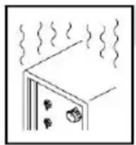
• OVERUSE can cause OVERHEATING.
natural_image
Simple line drawing of a door with steam rising, no text or symbols present- Allow cooling period; follow rated duty cycle.
- Reduce duty cycle before starting to weld again.
1-4. Warnings

Welding or cutting equipment produces fumes or gases which contain chemicals known to the State of California to cause birth defects and, in some cases, cancer.
Battery posts, terminals and related accessories contain lead and lead compounds, chemicals known to the State of California to cause cancer and birth defects or other reproductive harm. Wash hands after handling.

This product contains chemicals, including lead, known to the state of California to cause cancer, birth defects, or other reproductive harm. Wash hands after use.
For Gasoline Engines:

Engine exhaust contains chemicals known to the State of California to cause cancer, birth defects, or other reproductive harm.
For Diesel Engines:
Diesel engine exhaust and some of its constituents are known to the Sta of California to cause cancer, birth defects, and other reproductive harm.
1-5. EMF Information
Electric current flowing through any conductor causes localized electric and magnetic fields (EMF). Welding current creates an EMF field around the welding circuit and welding equipment. EMF fields may interfere with some medical implants, e.g. pacemakers. Protective measures for persons wearing medical implants have to be taken. For example, access restrictions for passerby or individual risk assessment for welders. All welders should use the following procedures in order to minimize exposure to EMF fields from the welding circuit:
- Keep cables close together by twisting or taping them, or using a cable cover
- Do not place your body between welding cables. Arrange cables to one side and away from the operator.
- Do not coil or drape cables around your body.
- Keep head and trunk as far away from the equipment in the welding circuit a possible.
- Connect work clamp to workpiece as close to the weld as possible.
- Do not work next to, sit or lean on the welding power source.
- Do not weld whilst carrying the welding power source or wire feeder.
About Implanted Medical Devices:
Implanted Medical Device wearers should consult their doctor and the device manufacturer before performing or going near arc welding, spot welding, gouging, plasma arc cutting, or induction heating operations. If cleared by your doctor, then following the above procedures is recommended.
SECTION 2- INTRODUCTION
Resistance welding is one of the oldest of the electric welding processes in use industry today. The weld is made by a combination of heat, pressure, and time. the name resistance welding implies, it is the resistance of the material to be welded to current flow that causes a localized heating in the part. The pressure exerted by the tongs and electrode tips, through which the current flows, holds th
parts to be welded in intimate contact before, during, and after the welding current time cycle. The required amount of time current flows in the joint is determined by material thickness and type, the amount of current flowing, and the cross-sectional area of the welding tip contact surfaces.
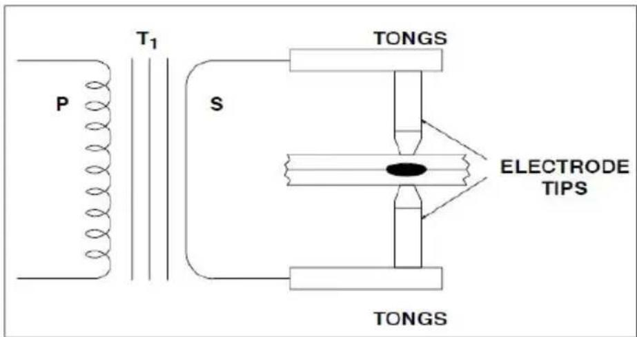
Figure 2-1. Resistance Spot Welding Machine With Work
In Figure 2-1, a complete secondary resistance spot welding circuit is illustrated. For clarity, the various parts of the resistance spot welding machine are identified. Some technical parameters is shown on the nameplate of the resistance spot welding machine.
SYMBOL AND MEANING ON DATA PLATE
U1: Rated AC input voltage of the welding power source
50H_z or 60H : Rated frequency of single phase AC power supply.
I_1max : Max. input current.
I_1eff : Max. effective input current.
X: Rated duty cycle. It is the ratio between the load duration time and the full cycle time.
Note1: This ratio is between 0\~100%.
Note2: For this standard, one full cycle time is 30 second. For example, if the rat 10% , the loaded time shall be 3 second and rest time shall be 7 second. If it is more than 3 second during several successive 10 second periods, it may overheat U_0 : Non-load voltage
It is the open-circuit output voltage of the welding power source.
S1: The rated Input Power, KVA
IP : Protection grade . For example, IP21, approving the welding machine as suitable for use indoors; IP23,. approving the welding machine as suitable for use outdoors in the rain.
Class of Insulation: H
ENVIRONMENTAL CONDITIONS
Welding power sources shall be capable of delivering their rated output when the following environmental conditions prevail:
a) range of the temperature of the ambient air:
$$ \begin{array}{l} \text { during operation: } \quad - 1 0 ^ {\circ} \mathrm{C} \text { to } + 4 0 ^ {\circ} \mathrm{C}; \ \text { after transport and storage at: } \quad - 2 0 ^ {\circ} \mathrm{C} \text { to } + 5 5 ^ {\circ} \mathrm{C}; \ \end{array} $$
b) relative humidity of the air:
$$ \text { up to } 50 \% \text { at } 40 ^ {\circ} \mathrm{C}; $$
$$ \text { up to } 90 \% \text { at } 20 ^ {\circ} \mathrm{C}; $$
c) ambient air, free from abnormal amounts of dust, acids, corrosive gases or substances, etc. other than those generated by the welding process;
d) altitude above sea level up to 1 000 m;
e) base of the welding power source inclined up to 10°.
SECTION3- FUNDAMENTALS OF RESISTANCE SPOT WELDI
3-1. Principle
Resistance welding is accomplished when current is caused to flow through electrode tips and the separate pieces of metal to be joined. The resistance of t base metal to electrical current flow causes localized heating in the joint, and the weld is made. The resistance spot weld is unique because the actual weld nugget is formed internally with relation to the surface of the base metal. Figure 4-1 show a resistance spot weld nugget compared to a gas tungsten-arc (TIG) spot weld.
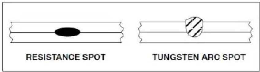
Figure 3-1. Resistance And TIG Spot Weld Comparison
The gas tungsten-arc spot is made from one side only. The resistance spot weld normally made with electrodes on each side of the workpiece. Resistance spot welds may be made with the workpiece in any position.
The resistance spot weld nugget is formed when the interface of the weld joint is heated due to the resistance of the joint surfaces to electrical current flow. In all cases, of course, the current must flow or the weld cannot be made. The pressure of the electrode tips on the workpiece holds the part in close and intimate contact during the making of the weld. Remember, however, that resistance spot welding machines are NOT designed as force clamps to pull the workpieces together for welding.
3-2. Heat Generation
A modification of Ohm's Law may be made when watts and heat are considered synonymous. When current is passed through a conductor the electrical
resistance of the conductor to current flow will cause heat to be generated. The basic formula for heat generation may be stated:
$$ \begin{array}{l} H = ^ {2} R \text { where } H = \text { Heat } \ I ^ {2} = \text { Welding Current Squared } \ R = \text { Resistance } \ \end{array} $$
The secondary portion of a resistance spot welding circuit, including the parts to welded, is actually a series of resistances. The total additive value of this electric resistance affects the current output of the resistance spot welding machine and the heat generation of the circuit.
The key fact is, although current value is the same in all parts of the electrical circuit, the resistance values may vary considerably at different points in the circuit. The heat generated is directly proportional to the resistance at any point in the circuit.

flowchart
graph TD
    A["START"] --> B["SQUEEZE TIME"]
    B --> C["HEAT OR WELD TIME"]
    C --> D["HOLD TIME"]
    D --> E["OFF TIME"]
Figure 3-2. Spot Welding Time Cycle
SQUEEZE TIME -Time between pressure application and weld.
HEAT OR WELD TIME - Weld time is cycles.
HOLD TIME - Time that pressure is maintained after weld is made.
OFF TIME - Electrodes separated to permit moving of material for next spot.
The resistance spot welding machines are constructed so minimum resistance will be apparent in the transformer, flexible cables, tongs, and electrode tips. The resistance spot welding machines are designed to bring the welding current to the weldment in the most efficient manner. It is at the weldment that the greatest relative resistance is required. The term "relative" means with relation to the rest the actual welding circuit.
There are six major points of resistance in the work area. They are as follows:
- The contact point between the electrode and top workpiece.
- The top workpiece.
- The interface of the top and bottom workpieces.
- The bottom workpiece.
- The contact point between the bottom workpiece and the electrode.
- Resistance of electrode tips.
The resistances are in series, and each point of resistance will retard current flow. The amount of resistance at point 3, the interface of the workpieces, will depend on the heat transfer capabilities of the material, its electrical resistance, and the combined thickness of the materials at the weld joint. It is at this part of the circle that the nugget of the weld is formed.
3-3. The Time Factor
Resistance spot welding depends on the resistance of the base metal and the amount of current flowing to produce the heat necessary to make the spot weld. Another important factor is time. In most cases several thousands of amperes are used in making the spot weld. Such amperage values, flowing through a weld. Such amperage values, flowing through a relatively high resistance, will create a lot of heat in a short time. To make good resistance spot welds, it is necessary have close control of the time the current is flowing. Actually, time is the only controllable variable in most single impulse resistance spot welding applications. Current is very often economically impractical to control. It is also unpredictable in many cases.
Most resistance spot welds are made in very short time periods. Since alternating current is normally used for the welding process, procedures may be based on a 60 cycle time (sixty cycles = 1 second). Figure 3-2 shows the resistance spot welding time cycle.
Previously, the formula for heat generation was used. With the addition of the time element, the formula is completed as follows:
$$ H = ^ {2} \text { RTK where } H = \text { Heat } $$
$$ I ^ {2} = \text { Current Squared } $$
$$ R = \text { Resistance } $$
$$ T = \text { Time } $$
$$ K = \text { Heat Losses } $$
Control of time is important. If the time element is too long, the base metal in the joint may exceed the melting (and possibly the boiling) point of the material. This could cause faulty welds due to gas porosity. There is also the possibility of expulsion of molten metal from the weld joint, which could decrease the cross section of the joint weakening the weld. Shorter weld times also decrease the possibility of excessive heat transfer in the base metal. Distortion of the welded parts is minimized, and the heat affected zone around the weld nugget is substantially smaller.
3-4. Pressure
The effect of pressure on the resistance spot weld should be carefully considered. The primary purpose of pressure is to hold the parts to be welded in intimate
contact at the joint interface. This action assures consistent electrical resistance and conductivity at the point of weld. The tongs and electrode tips should NOT be used to pull the workpieces together. The resistance spot welding machine is not designed as an electrical "C" clamp! The parts to be welded should be in intimate contact BEFORE pressure is applied.
Investigations have shown that high pressures exerted on the weld joint decrease the resistance at the point of contact between the electrode tip and the workpiece surface. The greater the pressure the lower the resistance factor.
Proper pressures, with intimate contact of the electrode tip and the base metal, would tend to conduct heat away from the weld. Higher currents are necessary with greater pressures and, conversely, lower pressures require less amperage from the resistance spot welding machine. This fact should be carefully noted particularly when using a heat control with the various resistance spot welding machines.
3-5. Electrode Tips
Copper is the base metal normally used for resistance spot welding tongs and tip. The purpose of the electrode tips is to conduct the welding current to the workpiece, to be the focal point of the pressure applied to the weld joint, to conheat from the work surface, and to maintain their integrity of shape and characteristics of thermal and electrical conductivity under working conditions.
Electrode tips are made of copper alloys and other materials. The Resistance Welders Manufacturing Association (RWMA) has classified electrode tips into two groups:
Group A - Copper based alloys
Group B - Refractory metal tips
The groups are further classified by number. Group A, Class I, II, III, IV, and V made of copper alloys. Group B, Class 10, 11, 12, 13, and 14 are the refractory alloys.
Group A, Class I electrode tips are the closest in composition to pure copper. A the Class Number goes higher, the hardness and annealing temperature values increase, while the thermal and electrical conductivity decreases.
Group B compositions are sintered mixtures of copper and tungsten, etc., designed for wear resistance and compressive strength at high temperatures.
Group B, Class 10 alloys have about 40 percent the conductivity of copper with conductivity decreasing as the number value increases. Group B electrode tips are not normally used for applications in which resistance spot welding machines would be employed.
3-6. Practical Uses Of Resistance Spot Welding
▲SPOT WELDING can be hazardous. Read and follow Safety Section at front of this book as well as the Owner's Manual and all labels on the equipment
Resistance spot welding techniques do not require extensive or elaborate safety precautions. There are some common sense actions that can, however, prevent injury to the operator.
Anytime work is being done in a shop, it is a wise rule to wear safety glasses. Resistance spot welding is no exception to the rule! Very often metal or oxides are expelled from the joint area. Protection of the face and especially of the eyes in necessary to prevent serious injury.
Another area of concern is ventilation. This can be a serious problem when resistance spot welding galvanized metals (zinc coated) or metals with other coatings such as lead. The fumes from the welding operation have a certain toxicity which will cause illness to the operator. Proper ventilation can reduce the fume concentration in the welding area.
As explained in the preceding discussion on the fundamentals of resistance spot welding, there is a definite relationship between time, current, and pressure. Current and pressure help create the heat in the weld nugget.
If the weld current is too low for the application, current density is too weak to make the weld. This condition will also overheat the electrode tips which can cause them to anneal, mushroom, and possibly be contaminated. Even though time is increased, the amount of heat generated is less than the losses due to radiation and conduction in the workpiece and thermal conduction of the electrodes. The result is the possibility, with long weld times at low currents, of overheating the entire base metal area between the electrodes. This could cause burning of the top and bottom surfaces of the workpiece as well as possibly imbedding the electrode tips in the workpiece surfaces.
As current density is increased, the weld time is decreased proportionately. If, however, the current density becomes too high, there is the possibility of expelling
molten metal from the interface of the joint thereby weakening the weld. The idea: time and current density condition is somewhere just below the level of causing metal to be expelled.
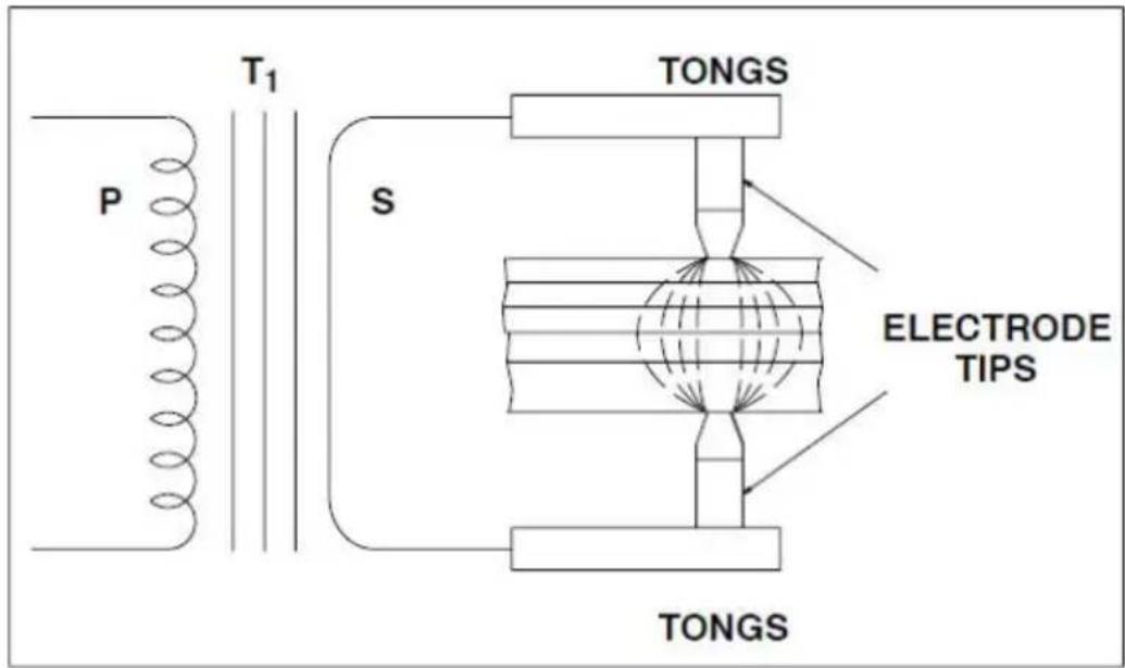
Figure 3-3. Resistance Spot Weld Heat Zones
It is apparent that the heat input cannot be greater than the total dissipation rate the workpiece and the electrode without having metal expelled from the joint. An interesting discovery has been developed recently concerning the flow of current through the workpiece. Until recently, current was considered to flow in a straight line through the weld joint. This is not necessarily true when multiple thicknesses of material are being welded. The characteristic is for the current to "fan out" thereby decreasing the current density at the point of weld the greatest distance from the electrode tips. The illustration (Figure 3-3) shows the resistance spot weld heat zones for several thicknesses of metal. We note that the uncontrollable variables (such as interface contamination) are multiplied when resistance spot welding several thicknesses of material. Quality levels will be much lower for "stack" resistance spot welding, which explains why such welding practices are avoided whenever possible.
Disregarding the quality factor, it becomes apparent that the number of thicknesses of a material which may be successfully resistance spot welded at or time will depend on the material type and thickness as well as the KVA capacity the resistance spot welding machine.
KVA rating, duty cycle, and other pertinent information is shown on DN-100E resistance spot welding machine nameplate. The catalog literature and the operating manual provide data on the maximum combined thicknesses of material that each unit can weld.
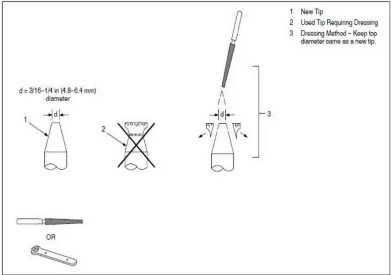
3-7. Electrode Tip Size
When you consider that it is through the electrode that the welding current is permitted to flow into the workpiece, it is logical that the size of the electrode tip point controls the size of the resistance spot weld. Actually, the weld nugget diameter should be slightly less than the diameter of the electrode tip point. If the electrode tip diameter is too small for the application, the weld nugget will small and weak. If, however, the electrode tip diameter is too large, there is danger of overheating the base metal and developing voids and gas pockets. In either instance, the appearance and quality of the finished weld would not be acceptable. To determine electrode tip diameter will require some decisions on the part of the weldment designer. The resistance factors involved for different materials will certainly have some bearing on electrode tip diameter determination. A general formula has been developed for low carbon steel. It will provide electrode tip diameter values that are usable for most applications.

The TIP DIAMETER discussed in this text refers to the electrode tip diameter at the point of contact with the workpiece. It does not refer to the major diameter of the total electrode tip.
3-8. Pressure Or Welding Force
The pressure exerted by the tongs and the electrode tips on the workpiece have great effect on the amount of weld current that flows through the joint. The great the pressure, the higher the welding current value will be, within the capacity of resistance spot welding machine.
Setting pressure is relatively easy. Normally, samples of material to be welded are placed between the electrode tips and checked for adequate pressure to make the weld. If more or less pressure is required, the operating manual for the resistance spot welding machine will give explicit directions for making the correct setting. A part of the setting up operation, the tong and electrode tip travel should be adjusted to the minimum required amount to prevent "hammering" the electrode tips and tip holders.
3-9. Miscellaneous Data
This section of the text is designed to provide information regarding several of the variables that occur in some resistance spot welding applications.
3-10. Heat Balance
There is no particular problem of heat balance when the materials to be welded are of equal type and thickness. The heat balance, in such cases, is automatically correct if the electrode tips are of equal diameter, type, etc. Heat balance may be defined as the conditions of welding in which the fusion zone of the pieces to be joined are subjected to equal heat and pressure.
When the weldment has parts of unequal thermal characteristics, such as copper and steel, a poor weld may result for several reasons. The metals may not alloy properly at the interface of the joint. There may be a greater amount of localized heating in the steel than in the copper. The reason would be because copper has low electrical resistance and high thermal transfer characteristics, while steel has high electrical resistance and low thermal transfer characteristics.
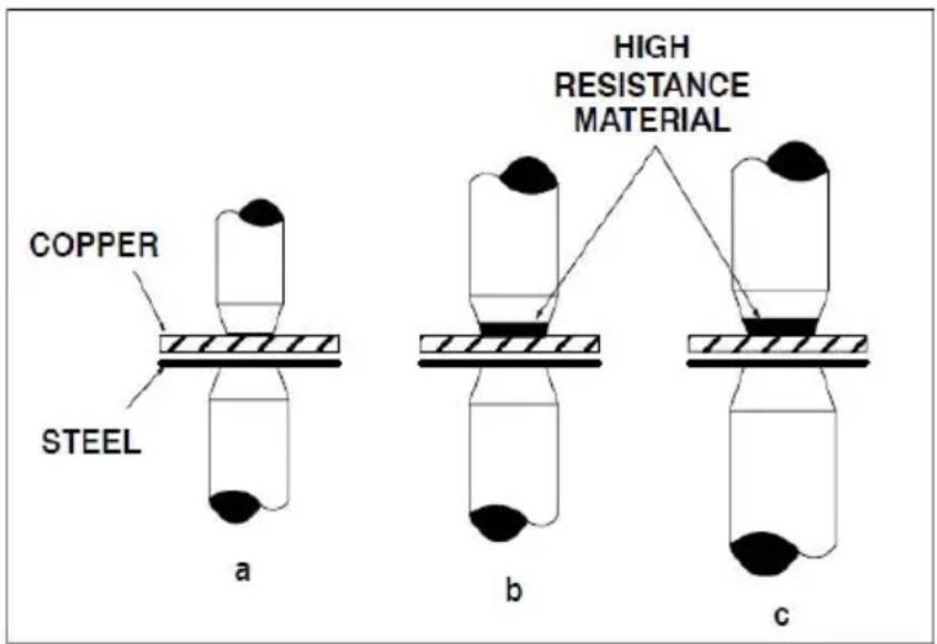
Figure 3-4. Techniques For Obtaining Heat Balance
Correct heat balance may be obtained in a weldment of this type by one of seven methods. Figure 3-4 Illustrates three possible solutions to the problem. Figure 3-4 (a) shows the use of a smaller electrode tip area for the copper side of the join equalize the fusion characteristics by varying the current density in the dissimilar materials.
Figure 3-4 (b) shows the use of an electrode tip with high electrical resistance material, such as tungsten or molybdenum, at the contact point. The result is to create approximately the same fusion zone in the copper as in the steel. A combination of the two methods is shown in Figure 3-4 (c).
3-11. Surface Conditions
All metals develop oxides which can be detrimental to resistance spot welding. Some oxides, particularly those of a refractory nature, are more troublesome than others. In addition, the mill scale found on hot-rolled steels will act as an insulated and prevent good quality resistance spot welding. Surfaces to be joined by this process should be clean, free of oxides, chemical compounds, and have a smooth surface.
3-12. Materials Data For Resistance Spot Welding
This section of the text will consider methods used for resistance spot welding some of the common metals that are used in fabrication work. It is not intended that all the possible problems that could arise will be answered. The purpose of this part of the text is to provide general operational data for use with resistance spot welding machines. Where applicable, the data provided will be related to specific models and size (KVA) of units. The units listed in this section are not recommended for aluminum or copper alloys.
3-13. Mild Steel
Mild or low-carbon steel comprises the largest percentage of material welded with the resistance spot welding process. All low-carbon steels are readily weldable with the process if proper equipment and procedures are used.
The carbon steels have a tendency to develop hard, brittle welds as the carbon content increases if proper post-heating procedures are not used. Quick
quenching of the weld, where the nuggets cools rapidly, increases the probability of hard, brittle micro-structure in the weld.
Hot rolled steel will normally have mill scale on the surface of the metal. This ty of material is usually not resistance spot welded with resistance welding machines of the KVA ratings of specific built units.
Cold rolled steel (CRS) and hot rolled steel, pickled and oiled (HRSP & O), may resistance spot welded with very little trouble. If the oil concentration is excessive
on the sheet metal, it could cause the formation of carbon at the electrode tips thereby decreasing their useful life. Degreasing or wiping is recommended for heavily oiled sheet stock.
The resistance spot weld should have shear strength equal to the base metal shear strength and should exceed the strength of a rivet or a fusion plug weld of the same cross sectional area. Shear strength is normally accepted as the criteria for resistance spot weld specifications, although other methods may be used.
A common practice is to "peel" two welded sample strips apart to see if a clean "rivet" is pulled from one piece. If it is, the resistance spot welding condition is considered correct.
With magnetic materials such as mild steel, the current through the weld can vary substantially depending on how much of the magnetic material is within the tong loop. The tong loop is sometimes called the "throat" of the resistance spot weldir machine.
For example, the part to be welded may have the largest amount of the base m within the throat of the unit for any one resistance spot weld and almost none of the base metal in the throat for the second spot weld. The current at the weld j will be less for the first weld. The reason is the reactance caused by the ferrous material within the arc welding circuit.
Resistance spot welding machines are applicable to low carbon steel welding. They must be used within their rated capacity of total thickness of material for b results. They should not be used over the duty cycle since damage to the contactor and transformer may result. The 30 percent duty cycle provided for this type of equipment should be adequate for all applications within their rating. The 30 percent duty cycle is a RWMA standard rating for general duty resistance welding machines. The 30 percent duty cycle is based on a 10 second time period and means the unit can weld 3 second out of each 10 second time period.
3-14. Low Alloy And Medium Carbon Steels
There are some pertinent differences in resistance spot welding low alloy and medium carbon steels as compared to mild or low carbon steels. The resistance factor for the low alloy and medium carbon steels is higher; therefore, the current requirements are slightly lower. Time and temperature are more critical since metallurgical changes will be greater with these alloys. There is certainly more
possibility of weld embrittlement than there is with mild steel.
Resistance spot welding pressures are normally higher with these materials because of the additional compressive strength inherent in the low alloy and medium carbon steels. It is always a good idea to use longer welding times when welding these alloys to retard the cooling rate and permit more ductile welds.
3-15. Stainless Steels
The chrome-nickel steel alloys (austenitic) have very high electrical resistance and are readily joined by resistance spot welding. The consideration of great importance with these materials is rapid cooling through the critical range, 800 to 1400 F. The rapid quench associated with resistance spot welding is ideal for reducing the possibility of chromium carbide precipitation at the grain boundaries. Of course, the longer the weldment is held at the critical temperatures the greater the possibility of carbide precipitation.
3-16. Steels, Dip Coated Or Plated
The overwhelming majority of material in this category is galvanized, or zinc coated steel. Although some galvanized steel is eletro-plated, the dip-coated costs less and is in predominant use. The zinc coating is uneven in thickness on dip-coated steel. The resistance factor will vary from weld to weld, and it is very difficult to set conditions in chart form for the material.
It is impossible to maintain the integrity of the galvanized coating when resistance spot welding. The low melting point of the zinc coating, compared to the fusion temperature of the steel sheet, causes the zinc to vaporize. Of course, there must be adequate pressure to force the zinc aside at the weld interface to permit steel-to-steel fusion. Otherwise, the strength of the resistance spot weld is open to question.
Materials are available to repair the external damage to the coating that may be incurred because of the welding heat. There is no remedy for the loss of coating material at the interfaces of the weld, unfortunately. In fact, the vaporization of the zinc can cause porosity in the weld and a general weakening of the expected shear strength.
▲The VAPORIZED ZINC, upon condensation to solid material, forms particles shaped like fishhooks. These particles CAN IMBED THEMSELVES IN THE TISSUES OF THE BODY and cause irritation. Use forced ventilation or exhaust a
the weld area and wear long sleeve shirts, long pants, and protective face shield when working with this process and coated material.
Other coated material, such as terne plate (lead coated) may have varying degrees of toxicity. Adequate ventilation is mandatory when working with these materials.
The vaporization of the coating material has a tendency to foul the electrode tips. The tips should be cleaned frequently to prevent the alloying of the lower melting materials with the copper tips. The tips may require cleaning and dressing every fourth or fifth weld to maintain quality in the product, although for some galvanize applications the best welds are made after several spots blacken the tips. The use of short weld times will increase the possibility of good welds with the least amount of tip fouling.
3-17. Aluminum And Aluminum Alloys
Resistance spot welding machines with KVA ratings much greater than 20 KVA are necessary to make sound welds on most aluminum materials and any other high conductivity type of base metal. The electrical conductivity of aluminum is high, and welding machines must provide high currents and exact pressures in order to provide the heat necessary to melt the aluminum and produce a sound weld.
3-18. Summary
Resistance spot welding is welding technique that is used for almost all known metals. The actual weld is made at the interface of the parts to be joined. The electrical resistance of the material to be welded causes a localized heating at the interfaces of the metals to be joined. Welding procedures for each type of material must be developed for the most satisfactory results.
It is possible that shunt currents flowing through a previously made spot weld will take welding current away from the second second spot weld to be made. This ' occur if the two spot welds are too close together, and it will happen with all metals.
Table 3-1 provides the rating information for a DN-100E resistance spot welding machine. These the rating information may be different between the different type of the DN -100E spot welding machine,for example, Rated supply voltage is 230V/120V,Rated supply frequency is 50Hz or 60Hz,Rated duty cycle is 30% or
50%, etc. These the rating information depends on the client's requirements. Table 3-1. Resistance Spot Welding Machine Specifications of a DN-100E spot welding machine
| Model | Rated Supply Voltage | Rated Supply Frequency | Rated Duty Cycle | No-load Voltage | Welding Thickness |
| DN-100E | U_1V ± 10% | 50/60Hz | 30% | 1.75V | 1.5+1.5mm |
The following general data is provided to assist the operator in setting up welding procedures when using the resistance spot welding machine.
Tong pressure settings should be made ONLY when the primary power cord is disconnected from the primary power input supply.
- Close tongs and measure space between electrode tip contact surfaces.
- Measure the thickness of the total weldment.
- Adjust tong gap to measurement of Step 2 less 1/2 the thickness of the thin weld number.
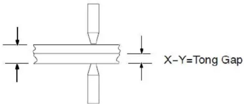
- Insert the parts to be welded between the electrode tips and bring tips to welding pressure. There should be a slight deflection of the tongs. This may be measured with a straight edge set on the tong longitudinal axis.
- Energize the spot welding machine and make a sample weld.
- Test the weld by visual and mechanical means. Check the electrode tip for deformation and contamination (see test procedures).
- Adjust tong pressure as required (see Operating Manual for tong adjustment procedures).
3-19. Test Procedures
The test procedures outlined are very simple and require a minimum of equipment to perform.
1. Visual Test
Observe the deformation and shape of the surface contact points at both sides of the weld. Excessive "dishing" of the surface contact point indicates one or more the following:
a. Excessive tong pressure.
b. Weld time too long.
c. Misalignment of the electrode tips.
If the resistance spot weld does not have an even, concentric surface appearance, the problem could be misalignment of the electrode tips. Align electrode tips with the power off and a typical weld joint between the tip surfaces.
2. Mechanical Test
Place one end of the resistance spot weld sample in vice jaws. Use mechanical means to force the weld apart. One side of the weld should pull loose from the parent metal with a metal extension from the weld. Check for proper weld diameter.
SECTION4- MAINTENANCE AND TROUBLESHOOTIN
4-1. Maintenance
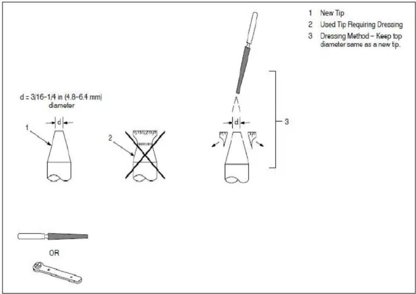
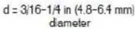
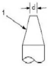
4-2. Dressing Tips
4-3. Troubleshooting
| Trouble | Remedy |
| Tips overheating. | Not enough tong pressure. Increase tong pressure. |
| Weld time too long. Reduce weld time. | |
| Material too thick for the spot welding machine. | |
| Tips arcing on material. | Not enough tong pressure. Increase tong pressure. |
| Tips not aligned correctly. Realign tips or dress tips to pro diameter (see Section 4-2). | |
| Base material may be welded to tips causing high resistant and poor electrical current flow. Clean or dress tips (see Section 4-2). |

| Spatter or molten material being expelled out during welding operation. | Incorrect tip alignment. Dress tips so that they align and a on the material (see Section 4-2). |
| Excessive tong pressure. Reduce tong pressure. | |
| Output amperage too high. Reduce amperage setting, if applicable (not available on air-cooled models). | |
| Weld time too long. Reduce weld time. | |
| Inconsistent weld nugget. | Inconsistent weld time. Install a weld timer, if applicable. |
| Not enough tong pressure. Increase tong pressure. | |
| Hole in middle of weld. | Contact area of tips is too large. Change to a smaller tip diameter or dress tips back to original diameter (see Section 4-2). |
| Poor weld or no weld at tips. | Material too thick for spot welding machine. Check that material thickness is within capacity of spot welding machin |
| Tongs are too long. Reduce tong length. | |
| Remove coating from material for intimate contact between pieces. Remove oxides and chemical compounds including galvanized coating. |
Made In China
VEVOR®
TOUGH TOOLS, HALF PRICE
Technical Support and E-Warranty Certificate
www.vevor.com/support
VEVOR®
TOUGH TOOLS, HALF PRICE
We continue to be committed to provide you tools with competitive price. "Save Half", "Half Price" or any other similar expressions used by us only repressor estimate of savings you might benefit from buying certain tools with us compared to top brands and does not necessarily mean to cover all categories of tools offered by are kindly reminded to verify carefully when you are placing an order with us if you actually saving half in comparison with the top major brands.
VEVOR®
TOUGH TOOLS, HALF PRICE
SPOT WELDER
MODÈLE:DN-100E
natural_image
Industrial electrical tool with copper pipe and yellow base, connected to black and white cables (no visible text or symbols)NEED HELP? CONTACT US!
Have product questions? Need technical support? Please feel free contact us:
Technical Support and E-Warranty Certificate www.vevor.com/support
This is the original instruction, please read all manual instructions carefully before operating. VEVOR reserves a clear interpretation of user manual. The appearance of the product shall be subject to the product you received. Please forgive us that we won't inform you there are any technology or software updates on our product.
Indicates special instructions.

natural_image
Four black-and-white icons representing warning symbols: exclamation, running figure, hand holding a leaf, and hand holding a building (no text or labels)natural_image
Silhouette of a hand holding a small object, possibly a device or tool, with no visible text or symbols.natural_image
Illustration of a person emitting smoke from a chimney, with a small container nearby (no text or symbols)natural_image
Silhouette of flames or smoke rising from a flame (no text or symbols)natural_image
Silhouette of a running person with a downward arrow above (no text or symbols)SECTION 2- INTRODUCTION
Welding power sources shall be capable of delivering their rated output when the following environmental conditions prevail:
a) range of the temperature of the ambient air:
$$ \begin{array}{l} \text { during operation: } \quad - 1 0 ^ {\circ} \mathrm{C} \text { to } + 4 0 ^ {\circ} \mathrm{C}; \ \text { after transport and storage at: } \quad - 2 0 ^ {\circ} \mathrm{C} \text { to } + 5 5 ^ {\circ} \mathrm{C}; \ \end{array} $$
b) relative humidity of the air:
$$ \text { up to } 50 \% \text { at } 40 ^ {\circ} \mathrm{C}; $$
$$ \text { up to } 90 \% \text { at } 20 ^ {\circ} \mathrm{C}; $$
c) ambient air, free from abnormal amounts of dust, acids, corrosive gases or substances, etc. other than those generated by the welding process;
d) altitude above sea level up to 1 000 m;
e) base of the welding power source inclined up to 10^ .
SECTION3- FUNDAMENTALS OF RESISTANCE SPOT WELDI
3-1. Principe
$$ R = R \text { sistance } $$
$$ T = \text { Temps } $$
un. Pression excessive des pinces.
4-3. Dépannage
We continue to be committed to provide you tools with competitive price. "Save Half", "Half Price" or any other similar expressions used by us only repressor estimate of savings you might benefit from buying certain tools with us compared to top brands and does not necessarily mean to cover all categories of tools offered by are kindly reminded to verify carefully when you are placing an order with us if you actually saving half in comparison with the top major brands.
VEVOR®
TOUGH TOOLS, HALF PRICE
SPOT WELDER
MODELL: DN-100E

natural_image
Industrial electrical tool with copper pipe and yellow base, connected to black and white cables (no visible text or symbols)NEED HELP? CONTACT US!
Have product questions? Need technical support? Please feel free contact us:
Technical Support and E-Warranty Certificate www.vevor.com/support
This is the original instruction, please read all manual instructions carefully before operating. VEVOR reserves a clear interpretation of user manual. The appearance of the product shall be subject to the product you received. Please forgive us that we won't inform you there are any technology or software updates on our product.
Indicates special instructions.
natural_image
Four black-and-white symbolic icons: warning triangle, running figure, hand holding a leaf, and hand reaching upward (no text or labels)natural_image
Silhouette of a hand holding a pen or stylus, no text or symbols presentnatural_image
Silhouette of a person emitting smoke from a cloud, with a small object below (no text or symbols)natural_image
Silhouette of a flame-like shape with jagged edges, resembling a stylized flame or smoke (no text or symbols)natural_image
Silhouette of a running person with a downward arrow above it (no text or symbols)natural_image
Simple line drawing of a door with steam rising (no text or symbols)SECTION 2- INTRODUCTION
Welding power sources shall be capable of delivering their rated output when the following environmental conditions prevail:
a) range of the temperature of the ambient air:
during operation: -10^ to +40^ ;
after transport and storage at: -20 °C to +55 °C;
b) relative humidity of the air:
up to 50 % at 40 °C;
up to 90 % at 20 °C;
c) ambient air, free from abnormal amounts of dust, acids, corrosive gases or substances, etc. other than those generated by the welding process;
d) altitude above sea level up to 1 000 m;
e) base of the welding power source inclined up to 10°.
SECTION3- FUNDAMENTALS OF RESISTANCE SPOT WELDI
3-1. Prinzip
$$ H = \mathrm{fR} \text {wobei} H = W \text {ärme} $$
4-3. Fehlerbehebung
natural_image
Industrial electrical tool with copper heating element and black wiring (no visible text or symbols)HO BISOGNO DI AIUTO? CONTATTACI!
Indicates special instructions.

natural_image
Four black-and-white icons representing warning symbols: exclamation, pictogram, hand holding a leaf, and hand holding a building (no text or labels)natural_image
Simple line drawing of a hand holding a bell (no text or symbols)natural_image
Simple icon showing a person emitting smoke from a chimney, with a falling object below (no text or symbols)natural_image
Abstract black-and-white graphic of flame-like shapes (no text or symbols)natural_image
Silhouette of a person running with a downward arrow above (no text or symbols)natural_image
Simple line drawing of a showerhouse with steam rising from its chimney (no text or symbols)Welding power sources shall be capable of delivering their rated output when the following environmental conditions prevail:
a) range of the temperature of the ambient air:
$$ \begin{array}{l} \text { during operation: } \quad - 1 0 ^ {\circ} \mathrm{C} \text { to } + 4 0 ^ {\circ} \mathrm{C}; \ \text { after transport and storage at: } \quad - 2 0 ^ {\circ} \mathrm{C} \text { to } + 5 5 ^ {\circ} \mathrm{C}; \ \end{array} $$
b) relative humidity of the air:
$$ \text { up to } 50 \% \text { at } 40 ^ {\circ} \mathrm{C}; $$
$$ \text { up to } 90 \% \text { at } 20 ^ {\circ} \mathrm{C}; $$
c) ambient air, free from abnormal amounts of dust, acids, corrosive gases or substances, etc. other than those generated by the welding process;
d) altitude above sea level up to 1 000 m;
e) base of the welding power source inclined up to 10^ .
$$ H = I 2 R T K \quad \text { dove } H = \text { Calore } $$
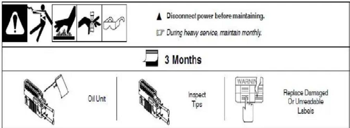
|  |  |  | ▲ Disconnect power before maintaining. ☐ During heavy service, maintain monthly. | |
| 3 Months | ||||
| Oil Unit | Inspect Tips | WARNIN Replace Damaged Or Unreadable Labels | ||
elettronica www.vevor.com/support
VEVOR®
TOUGH TOOLS, HALF PRICE
natural_image
Industrial electrical tool with copper heating element and black wiring (no visible text or symbols)Indicates special instructions.

natural_image
Four black-and-white icons representing warning symbols: exclamation, falling figure, hand holding leaf, and hand reaching up (no text or labels)natural_image
Illustration of a person emitting smoke from a chimney with a falling object below (no text or symbols)natural_image
Abstract black-and-white graphic of flame-like shapes (no text or symbols)natural_image
Silhouette of a person running with a downward arrow above (no text or symbols)natural_image
Simple line drawing of a door with steam rising from its side (no text or symbols)Welding power sources shall be capable of delivering their rated output when the following environmental conditions prevail:
a) range of the temperature of the ambient air:
$$ \begin{array}{l l} \text { during operation: } & - 1 0 ^ {\circ} \mathrm{C} \text { to } + 4 0 ^ {\circ} \mathrm{C}; \ \text { after transport and storage at: } & - 2 0 ^ {\circ} \mathrm{C} \text { to } + 5 5 ^ {\circ} \mathrm{C}; \end{array} $$
b) relative humidity of the air:
$$ \begin{array}{l} \text {up to 50\% at 40^{\circ} C}; \ \text {up to 90\% at 20^{\circ} C}; \end{array} $$
c) ambient air, free from abnormal amounts of dust, acids, corrosive gases or substances, etc. other than those generated by the welding process;
d) altitude above sea level up to 1 000 m;
e) base of the welding power source inclined up to 10^ .
4-3. Solución de problemas
natural_image
Industrial electrical device with copper heating element and black wiring (no visible text or symbols)POTRZEBUJE POMOCY? SKONTAKTUJ SIĘ Z NAMI!
Indicates special instructions.

natural_image
Four black-and-white icons representing warning symbols: exclamation, falling figure, hand holding leaf, and hand reaching up (no text or labels)natural_image
Abstract black-and-white graphic of flame-like shapes (no text or symbols)natural_image
Silhouette of a person running with a downward arrow above (no text or symbols)Welding power sources shall be capable of delivering their rated output when the following environmental conditions prevail:
a) range of the temperature of the ambient air:
$$ \begin{array}{l l} \text { during operation: } & - 1 0 ^ {\circ} \mathrm{C} \text { to } + 4 0 ^ {\circ} \mathrm{C}; \ \text { after transport and storage at: } & - 2 0 ^ {\circ} \mathrm{C} \text { to } + 5 5 ^ {\circ} \mathrm{C}; \end{array} $$
b) relative humidity of the air:
$$ \begin{array}{l} \text {up to 50\% at 40 ^ {\circ} C}; \ \text {up to 90\% at 20 ^ {\circ} C}; \end{array} $$
c) ambient air, free from abnormal amounts of dust, acids, corrosive gases or substances, etc. other than those generated by the welding process;
d) altitude above sea level up to 1 000 m;
e) base of the welding power source inclined up to 10^ .
$$ H = I 2 R T K \quad g d z i e H = c i e p \text { to } $$
3-19. Procedury testowe
www.vevor.com/support
VEVOR®
TOUGH TOOLS, HALF PRICE
Technische ondersteuning en e-garantiecertificaat www.vevor.com/support
PUNTLASMACHINE
MODEL: DN-100E
natural_image
Industrial electrical tool with copper heating element and black wiring (no visible text or symbols)HULP NODIG? NEEM CONTACT MET ONS OP!
Indicates special instructions.
natural_image
Warning symbol: black exclamation mark with exclamation mark (no text or numbers)


natural_image
Simple icon showing a person emitting smoke from a pile of gases, with no text or symbols present.natural_image
Abstract black-and-white graphic of flame-like shapes (no text or symbols)natural_image
Silhouette of a person running with a downward arrow above (no text or symbols)natural_image
Simple line drawing of a door with steam rising, no text or symbols presentWelding power sources shall be capable of delivering their rated output when the following environmental conditions prevail:
a) range of the temperature of the ambient air:
$$ \begin{array}{l} \text { during operation: } \quad - 1 0 ^ {\circ} \mathrm{C} \text { to } + 4 0 ^ {\circ} \mathrm{C}; \ \text { after transport and storage at: } \quad - 2 0 ^ {\circ} \mathrm{C} \text { to } + 5 5 ^ {\circ} \mathrm{C}; \ \end{array} $$
b) relative humidity of the air:
$$ \text { up to } 50 \% \text { at } 40 ^ {\circ} \mathrm{C}; $$
$$ \text { up to } 90 \% \text { at } 20 ^ {\circ} \mathrm{C}; $$
c) ambient air, free from abnormal amounts of dust, acids, corrosive gases or substances, etc. other than those generated by the welding process;
d) altitude above sea level up to 1 000 m;
e) base of the welding power source inclined up to 10^ .
SECTIE 3 - BASISBEGINSELEN VAN WEERSTANDSPUNTLASSEN
3-1. Principe
Figuur 3-3. Weerstandspuntlas-hittezones
4-2. Aankleedtips
4-3. Probleemoplossen
natural_image
Industrial electrical tool with copper heating element and black wiring (no visible text or symbols)BEHÖVS HJÄLP? KONTAKTA OSS!
Indicates special instructions.
natural_image
Four black-and-white icons representing warning symbols: exclamation, falling figure, hand holding leaf, and hand reaching up (no text or labels)natural_image
Illustration of a person emitting smoke from a chimney with a falling object below (no text or symbols)natural_image
Silhouette of a flame with flames, no text or symbols presentnatural_image
Silhouette of a person running with a downward arrow above (no text or symbols)natural_image
Simple line drawing of a steam heating inside a door with doors and smoke (no text or symbols)Bild 2-1. Motständspunktsvetsmaskin Med Arbete
I figur 2-1 visas en komplett sekundär resistanspunktsvetskrets.
Welding power sources shall be capable of delivering their rated output when the following environmental conditions prevail:
a) range of the temperature of the ambient air:
during operation: -10 ^ to +40 ^ ; after transport and storage at: -20 ^ to +55 ^ ;
b) relative humidity of the air:
up to 50 % at 40 °C; up to 90 % at 20 °C;
c) ambient air, free from abnormal amounts of dust, acids, corrosive gases or substances, etc. other than those generated by the welding process;
d) altitude above sea level up to 1 000 m;
e) base of the welding power source inclined up to 10^ .
AVSNITT 3- GRUNDLÄGGANDE MOTSTÅNDPUNKTSVETSNING
3-1. Princip
$$ H = I 2 R T K \quad d \text {är} H = V \text {ärme} $$
$$ I 2 = \text { Ström i kvadrat } $$
$$ R = \text { Motständ } $$
$$ T = T i d $$
4-2. Klädtips

4-3. Felsökning
www.vevor.com/support