MMA-140 - Welding machine Vevor - Free user manual and instructions
Find the device manual for free MMA-140 Vevor in PDF.

| Product type | MMA (stick) and Lift TIG welder |
| Brand | Vevor |
| Model | MMA-140 |
| Power supply | AC 110 V ±10% or 220 V ±10%, 50/60 Hz (compatible plug) |
| Output current | 30-140 A adjustable (depending on input voltage: 30-120 A at 110 V, 30-140 A at 220 V) |
| No-load voltage | 60 V |
| Rated power | 4.98 KVA |
| Duty cycle (at 40°C) | 15% (i.e., 1.5 min welding for 10 min cooling) |
| Power factor | 0.88 |
| Dimensions (approx.) | 35 x 20 x 25 cm |
| Weight (approx.) | 8 kg |
| Main functions | MMA (manual) welding, Lift TIG, VRD (electric shock prevention), Hot Start, Arc Force, Anti-stick, fine current adjustment, digital display |
| Thermal protection | Yes, automatic trigger in case of overheating, automatic reset after cooling |
| Maintenance and cleaning | Unplug before maintenance; blow out internal dust every 6 months; check the condition of cables and connectors |
| Safety | Requires training, wearing protective equipment (mask, gloves, fire-resistant clothing); avoid explosive atmospheres; do not expose to weather |
| Spare parts and repairability | Available parts: power cables, ground clamps, electrode holder; repairs reserved for a qualified professional |
| General information | IGBT inverter technology, compact and lightweight, suitable for steel, stainless steel, alloys; compatible with acidic, alkaline and cellulosic electrodes |
Frequently Asked Questions - MMA-140 Vevor
User questions about MMA-140 Vevor
0 question about this device. Answer the ones you know or ask your own.
Ask a new question about this device
Download the instructions for your Welding machine in PDF format for free! Find your manual MMA-140 - Vevor and take your electronic device back in hand. On this page are published all the documents necessary for the use of your device. MMA-140 by Vevor.
USER MANUAL MMA-140 Vevor
Technical Support and E-Warranty Certificate www.vevor.com/support
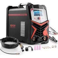
STICK WELDER
Applicable Model: MMA-140/MMA-160/MMA-200
We continue to be committed to provide you tools with competitive price. "Save Half", "Half Price" or any other similar expressions used by us only represents an estimate of savings you might benefit from buying certain tools with us compared to the major top brands and does not necessarily mean to cover all categories of tools offered by us. You are kindly reminded to verify carefully when you are placing an order with us if you are actually saving half in comparison with the top major brands.
VEVOR®
TOUGH TOOLS, HALF PRICE
Stick Welder
natural_image
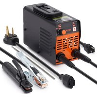
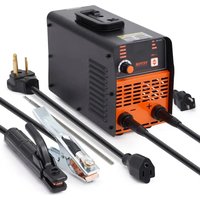
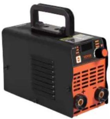
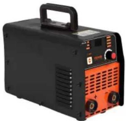
Black and orange portable electronic device with ventilation slots and a handle (no visible text or symbols)MMA-140
natural_image
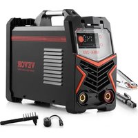
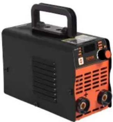
Black and orange portable electronic device with ventilation grilles and a handle (no visible text or symbols)MMA-160

natural_image
Black and orange portable electronic device with control panel and buttons (no visible text or symbols)MMA-200
NEED HELP? CONTACT US!
Have product questions? Need technical support? Please feel free to contact us: Technical Support and E-Warranty Certificate www.vevor.com/support
This is the original instruction, please read all manual instructions carefully before operating. VEVOR reserves a clear interpretation of user manual. The appearance of the product shall be subject to the product you received. Please forgive us that we won't inform you there are any technology or software updates on our product.
SAFETY
Welding is dangerous and may cause damage to you and others, so take good protection when welding. Please refer to the manufacturer's safety guidelines for accident prevention.
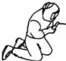
 | Professional training is needed before operating the machine. Use labor protection welding supplies authorized by the national security supervision department. Operators should have valid work permits for metal welding/cutting operations. Cut off power before maintenance or repair. | |
 | Electric shock may lead to serious injury even death. Install earthing devices according to the user's specification. Never touch the live parts with bare skin or while wearing wet gloves/clothes. Make sure that you are insulated from the ground and workpiece. Make sure that your working position is safe. | |
 | Smoke & gas may be harmful to health. Keep your head away from smoke and gas avoid inhalation of exhaust gas during welding. Keep the working environment well ventilated with exhaust or ventilation equipment when welding. | |
 | Arc radiation may damage eyes or burn sl Wear suitable welding masks and protective clothing to protect your eyes and body. Use suitable masks or screens to protect spectators from harm. | |
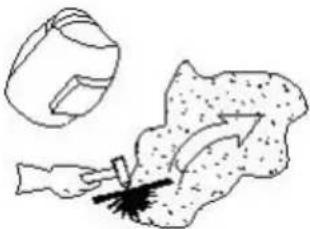
 | Improper operation may cause fire or explosion.● Welding sparks may result in a fire, so pleas check that no combustible materials are nearby and pay attention to fire hazards.● A fire extinguisher should be kept nearby, an it should be used by a trained person.● Do not weld in a confined space.● Do not use this machine for pipe thawing. | |
 | Hot workpiece may cause severe scalding.● Do not touch hot workpiece with bare hands.● Cooling is needed during continuous use of the welding torch. | |
 | Magnetic fields affect cardiac pacemaker.● Pacemaker users should stay be away from the welding area before medical consultation. | |
 | Please seek professional help when encountering machine failure.● Refer to the relevant contents of this manual you encounter any difficulties in installation and operation.● Contact the service center of your supplier to seek professional help if you do not fully understand the manual or solve a problem according to the manual. | |
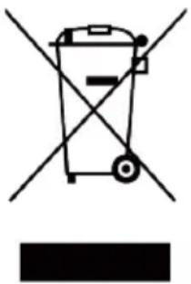 | CORRECT DISPOSAL for Display.● This product is subject to the provision of european Directive 2012/19/EU.The symbol showing a wheelie bin crossed through indicates that the product requires separate refuse collection in the European Union. This applies to the product and all accessories marked with this symbol. Products marked as such may not be discarded with normal domestic waste, but must be taken toacollection point for recycling electrical and electronic devices. | |
BRIEF INTRODUCTION OF THE PRINCIPLE
The welding machine uses an advanced inverter technology designed rectifier. The emergence of inverter arc welding equipment is due to the emergence of inverter power theory and devices. Inverter arc welding power supply is the use of a high-power device MOSFET field effect tube/IGBT single tube/module 50/60Hz power frequency electricity is converted to high frequency (18-100KHZ above), and then step-down rectifier, through the pulse width modulation technology (PWM) output high-power DC source, the weight of the main transformer, the volume is greatly reduced, the efficiency is increased by more than 30% . The adverse of the inverter welding machine is praised by experts as a revolution in the welding industry.
Hand arc welding machine can provide a stronger, more concentrated more stable arc in the short circuit droplet transition. The electrode and the workpiece react rapidly after the short circuit. In addition, this type of power supply can be equipped with an arc adjustment device, which means that the welding machine can be designed with different dynamic characteristics. The dynamic characteristics can be adjusted to make the arc softer or harder.
Hand arc welding machine series are characterized by: high efficiency, energy saving, light, good dynamic characteristics, arc stability, and easy control of solution pools. High no-load voltage and better energy thrust compensation are widely used. Can weld stainless steel, alloy steel, carbon steel, copper, and other non-ferrous metals. The welding machine can use a variety of different specifications and materials of an electrode, including acid, alkaline, and cellulose electrode can be used for aerial wo fieldwork, and indoor and outdoor decoration. Compared with similar products at home and abroad, it has the characteristics of small size, lightweight, simple installation, easy operation, and so on.
INSTALLATION
Main paramter
| ITEM | MMA-140 | |
| Power Voltage(V) | AC 110V ±10% | AC 220V ±10% |
| Frequency(HZ) | 50HZ-60HZ | 50HZ-60HZ |
| Rated input power(KVA) | 4.98 4.98 | |
| Duty cycle(40°C) | 15%/40°C | 15%/40°C |
| No load voltage(V) | 60V | 60V |
| Output current(A) | 140A ±10A | 140A ±10A |
| Power factor | 0.88 | 0.88 |
INSTALLATION
Main paramter
| ITEM | MMA-160 | |
| Power Voltage(V) | AC 110V/220V ±10% | AC 220V ±10% |
| Frequency(HZ) | 50HZ-60HZ | 50HZ-60HZ |
| Rated input power(KVA) | 5.87 5.87 | |
| Duty cycle(40°C) | 20%/40°C | 20%/40°C |
| No load voltage(V) | 60V | 60V |
| Output current(A) | 160A ±10A | 160A ±10A |
| Power factor | 0.88 | 0.88 |
INSTALLATION
Main paramter
| ITEM | MMA-200 | |
| Power Voltage(V) | AC 110V/220V ±10% | AC 220V ±10% |
| Frequency(HZ) | 50HZ-60HZ | 50HZ-60HZ |
| Rated input power(KVA) | 7.78 7.78 | |
| Duty cycle(40°C) | 20%/40°C | 20%/40°C |
| No load voltage(V) | 60V | 60V |
| Output current(A) | 200A ±10A | 200A ±10A |
| Power factor | 0.88 | 0.88 |
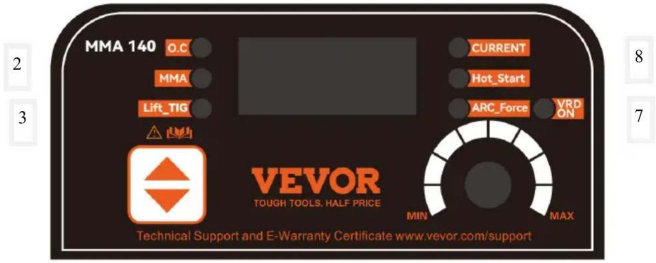
Control Panel Description
1
10
9
4
5
6
Note: The above images are for reference only
| Number | Explain |
| 1 | Abnormal indicator light |
| 2 | Manual welding status indicator light |
| 3 | Contact arc argon arc welding |
| 4 | Switch function keys, short press to switch between manual welding or argon arc welding |
| 5 | Thrust (refers to the welding force generated by the welding machine through parameters such as output current, voltage, and power during welding) |
| 6 | Short press the parameter knob to switch, rotate to adjust size |
| 7 | Anti electric shock indicator light (When the VRD function is turned on, the no-load voltage of the welding machine usually does not exceed 20V, which helps to carry out welding work in damp or other environments that are prone to electric shock, thereby significantly reducing the risk of electric shock for welding personnel). At the same time, press the function key and parameter knob, and the indicator light will light up as VRD on and off as VRD off |
| 8 | Thermal arc ignition (by increasing the length and strength of the arc, increasing the temperature and heat of the arc, accelerating the melting of the workpiece and electrode, thereby improving welding speed and quality) |
| 9 | Current regulation indicator light |
| 10 | Current display |
Functional Diagram
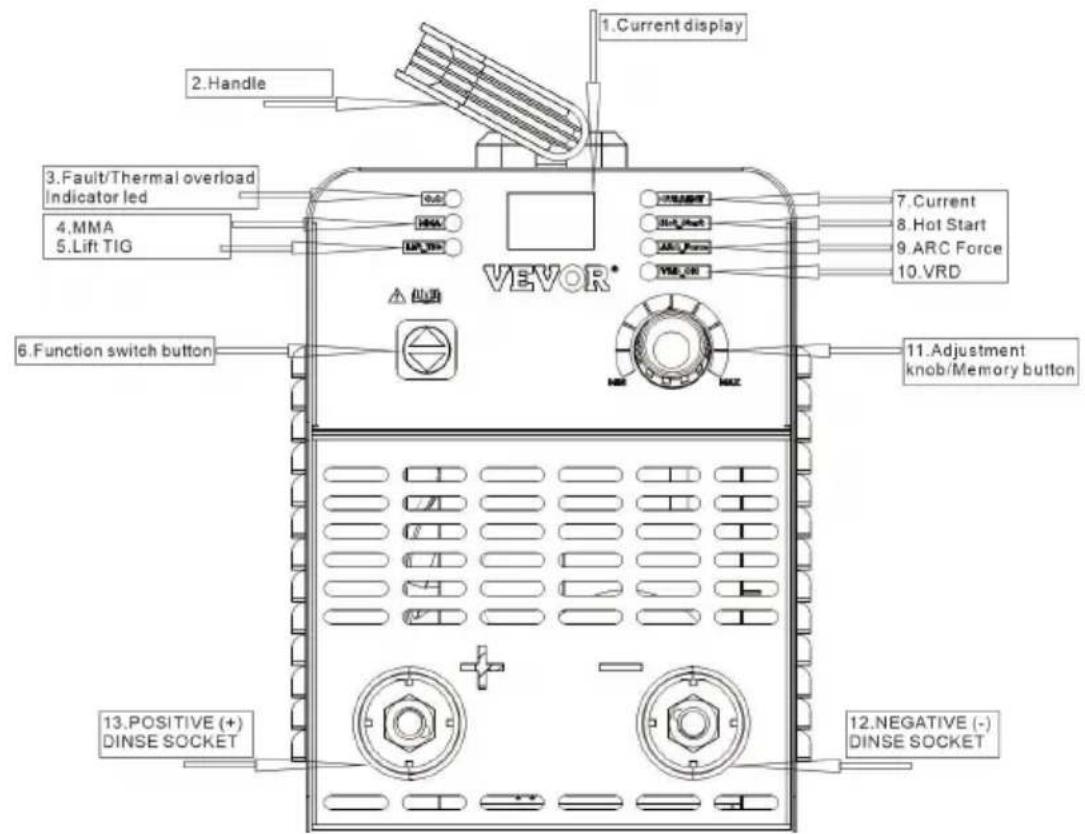
MMA Installation
Installation and Connection Diagram
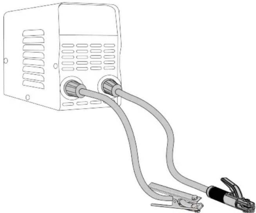
natural_image
Line drawing of a portable electrical device with two cables connected to its connectors (no text or symbols)TIG Installation
Installation and Connection Diagram
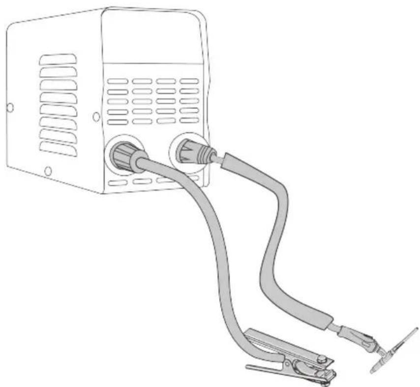
natural_image
Line drawing of a portable device with two cables connected, one showing internal components and the other attached to a clip (no text or symbols)SITE SELECTION
! BE SURE TO OPERATE THE WELDER ACCORDING TO TH FOLLOWING GUIDELINES:
• In areas free from moisture and dust;
- In areas with an ambient temperature between 14^ to 104^ ;
- In areas free from oil, steam, and corrosive gases.
- In areas not subjected to abnormal vibration or shock;
- In areas not exposed to direct sunlight or rain;
- Place at a distance of 12" or more from walls or similar obstructions that could restrict natural airflow for cooling.
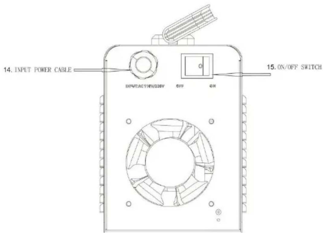
Power Source Connection
Make sure that the ON/OFF SWITCH is OFF before you make any electrical connection. The power supply voltage and frequency available at the site are those stated in the rating label of your welder.
The main power supply voltage should be within ±10% of the rated main power supply voltage. Too low a power supply voltage may cause poor welding performance. Too high a power supply voltage will cause components to overheat and possibly fail. The welder outlet must be:
- Correctly installed, if necessary, by a qualified electrician.
- Correctly grounded (electrically) under national and local regulations.
- Connected to an electric circuit that is rated for sufficient amperage pe the rating label of your welder.
If you are unsure of any of the above, have your outlet inspected by a qualified electrician before using the welder.
NOTE:
- Periodically inspect the INPUT POWER CABLE for any cracks or exposed wires. If it is not in good condition, have it repaired by a Service Center.
- Do not cut off the grounding prong or alter the plug in any way, and not use any adapters between the
welder's INPUT POWER CABLE and the power source receptacle.
- Do not violently pull the INPUT POWER CABLE to disconnect it from power outlet.
- Do not lay material or tools on the INPUT POWER CABLE. The INPU POWER CABLE may be damaged and result in electrical shock.
- Keep the INPUT POWER CABLE away from heat sources, oils, solvent or sharp edges.
- Do not use this welder on a circuit with a Ground Fault Circuit Interru (GFCI) on it. GFCIs are tripped by welding arcs and your welding operations will be interrupted regularly.
Generators
This welder can be operated from an AC generator. Ensure that the generator can supply a minimum of 5,000
watts of continuous output. The generator must not have an auto-idle fuel-saving feature, and must have the option to turn the auto-idle off. The generator must run at full speed at all times while your welder is plugge into it, or you risk damaging your welder. Any other power draws on the generator or anything that reduces the generator RPM may damage your welder.
Extension Cords
For optimum welder performance, an extension cord should not be used unless absolutely necessary. If necessary, care must be taken in selecting an extension cord appropriate for use with your specific welder.
Select a properly grounded extension cord that will connect directly with the AC power source receptacle and the welder INPUT POWER CABLE without the use of adapters. Make certain that the extension cord is properly wired and in good electrical condition. Extension cords must fit the following wire size guidelines:
- #12 AWG or larger wire
- Do not use an extension cord over 25 ft. in length.
Ventilation
Since the inhalation of welding fumes can be harmful, ensure that the welding area is effectively ventilated.
Additional Warnings
FOR YOUR SAFETY, BEFORE CONNECTING THE POWER SOURCE TO THE LINE CLOSELY FOLLOW THESE INSTRUCTIONS:
- An adequate two-pole breaker must be inserted before the main outlet. This breaker must be equipped with time-delay fuses.
- When working in a confined space, the welder must be kept outside the welding area and the ground cable should be fixed to the workpiece. New work in a damp or wet confined space.
- Do not use damaged INPUT POWER CABLE or welding cables.
- The welding torch/electrode should never be pointed at the operator or other people.
- The welder must never be operated without its panels attached. This
could cause serious injury to the operator and could damage the equipment.
OPERATION
Performance Data Plate and Duty Cycle
On the machine, there is a plate that includes all the operating specifications for your new unit. The serial number of the product is also found on this plate. The duty cycle rating of a welder defines how long operator can weld and how long the welder must rest and be cooled. The duty cycle is expressed as a percentage of 10 minutes and represents a maximum welding time limit. The balance of a 10-minute cycle is required for cooling. For example, a welder has a duty cycle rating of 30% at the rated output of 90A. This means with that machine can weld at 90 A out for three (3) minutes cut of 10 with the remaining seven (7) minutes required for cooling. The duty cycle of your new welder can be found or data plate affixed to the machine.
Internal Thermal Protection
The thermal protection system will engage, shutting off all welder output if you exceed the duty cycle of the welder. After cooling, the thermal protector will automatically reset, and the welding functions will resume. This is normal and automatic behavior from the machine. No user action is required during this phase. However, you should wait at least ten minutes after the thermal protector engages before resuming welding. You must do this even if the thermal protector resets itself before the ten minutes is up or you may experience less than specified duty cycle performance.
CAUTION:DO NOT REGULARLY EXCEED THE DUTY CYCLE OR DAMAGE TO THE WELDER CAN RESULT
Welding Preparation
An important factor in making a satisfactory weld is preparation. This includes studying the process and equipment and practicing welding before attempting to weld finished product. An organized, safe, ergonomic, comfortable, and well-lit work area should be prepared for the operator. The work area should especially be free of all flammables, and a fire extinguisher and a bucket of sand should be available.
To properly prepare for welding with your new welder, it is necessary to:
- Read the safety precautions at the front of this manual.
- Prepare an organized,well-lit work area.
- Provide protection for the eyes and skin of the operator and bystander
- Attach the ground clamp to the bare metal to be welded, ensuring good contact.
Plug the machine into a suitable outlet.
- Completely open the gas cylinder valve. Adjust the gas pressure regulator to the correct flow rate.
MMA function: Select MMA by up and down button.
- Under MMA: The Current/Hot Start / Arc Force can be selected.
After selecting, adjust the knob directly to adjust each function parameter; after adjusting, press the knob once to save and enter the next function parameter adjustment. After adjustment, 5S automatically save and exit to Current.
natural_image
Line drawing of a portable electronic device with ventilation slots and a top handle (no text or symbols)- Current: @110V, 30-120A adjustable; @220V, 30-140A
adjustable
Hot start: Superimposed current value (not exceeding the maximum current), 0-100A
Arc Force: superimposed current value (not exceeding the maximum current), 0-100A
-
Under MMA, press and hold the knob for 5S to switch Vrd.
-
Anti-stick: automatic, no need to operate
-
Acid welding rod: positive electrode connection welding pliers / negative grounding wire clamps
Alkaline welding rod : Negative welding pliers / positive grounding clamps
Electric arc welding
- Welding rod grade and diameter. It mainly depends on the nature of the material, the thickness of the weld, the form of the joint weld position weld parameters, and other factors. The relationship between the diameter
of the welding electrode and the thickness of the plate is as follows.
| Thickness of Welded Parts (mm) | <4 | 4 ~ 8 | >8 ~ 12 | >12 |
| Diameter of Welding Electrode (φmm) | ≤ 3.5 | φ3 ~ 4 | φ4 ~ 5 | φ5 ~ 6 |
- Welding Current: The welding current depends on the electrode, electrode diameter, thickness of the welded parts, and joint type weld position. Other factors to consider are the structural steel welding electrode flat welding positions, and the welding current based on the following empirical formula to primary selection.
K = Id I--Welding Current K--Empirical Coefficient d--Diameter of Welding Electrode
Relationship between the empirical coefficient of welding current and the diameter of the welding electrode.
| Diameter of Welding Electrode (mm) | 1.6 | 2 2.5 | 3 4 | 4 6 |
| Empirical Coefficient (A/mm) | 20 ~ 25 | 25 ~ 30 | 30 ~ 40 | 40 ~ 50 |
The current of vertical welding, horizontal welding, and over-head welding should be 10 \~ 20% less than that of flat welding. The current of fillet welding should be 10 \~ 20% larger than that of flat welding. For alloy steel electrodes, stainless steel electrodes, due to the high thermal expansion coefficient of resistance, if the current is high, the welding rod is prone to
reddening during the welding process and cause the flux skin to fall off, affecting the quality of welding.
- Connection method of welding output
The DC reverse connection method should be used for alkaline electrode welding.
Acid electrode welding should use a DC positive connection method.
MAINTENANCE & SERVICING
General Maintenance
This welder has been engineered to need minimal service, providing that few simple steps are taken for proper maintenance.
- Replace the INPUT POWER CABLE, ground cable, ground clamp, or torch/electrode cable when damaged or worn.
- Avoid directing grinding particles toward the welder. These conductive particles can build up inside the machine and cause severe damage.
- Periodically clean dust, dirt, and grease from your welder. Every six months or as necessary, remove the side panels from the welder and use compressed air to blow out any dust and dirt that may have accumulated inside the welder.
WARNING:DISCONNECT FROM POWER SOURCE WHEN CARRYIN OUT THIS
OPERATION.
- Check all cables periodically. They must be in good condition and not cracked.
WARNING: ELECTRIC SHOCK CAN KILL! Be aware of the ON/OFF SWITCH. The OFF switch does not remove power from all internal circuits in the welder. To reduce the risk of electric shock, always unplug the well from its AC power source and wait several minutes for electrical energy discharge before removing the side panels.
TROUBLESHOOTING
The following is a troubleshooting table provided to help you determine a possible remedy when you are having a problem with your welder.
This table does not provide all possible solutions, only those possibilities considered likely to be common faults.
| PROBLEM POSSIBLE CAUSE POSSIBLE SOLUTION | ||
| Neither INDICATOR LED is illuminated and nothing works on the welder. | Machine is not turned ON. | Turn machine ON with ON/OFF SWITCH |
| No input power present. | Make sure machine is plugged in.Verify that circuit breaker has not been tripped.Reset if needed.Verify output power from the outlet.Do not use the machine on a GFI outlet. | |
| INDICATOR LEDS are illuminated and there is no output power from the welder. | Exceeded duty cycle;thermal protector engaged. | Allow welder to cool at least 10 minutes with machine ON (observe and maintain proper duty cycle).FAULT/THERMAL OVERLOAD INDICATOR LED should turn off after the machine has cooled |
| Insufficient air flow causing machine to overheat before reaching duty cycle. | Check for obstructions blocking air flow and ensure that there are 12 inches of clearance between any obstacles and the vents on all sides of the machine. | |
| Incorrect voltage supplied to welder. | Check the voltage of your outlet. If it is 10% more or less than 120V, call a qualified electrician. | |
| Low output or non-penetrating weld. | Too long or improper extension cord. | Use a proper extension cord (#12 AWG wire or heavier,no longer than 25 ft.) |
| Poor ground connection or torch/electrode connection. | Reposition clamp and check cable to clamp connection.Check connection of ground cable,torch or electrode holder | |
| Input power too low. | Have a qualified electrician verify the voltage at your outlet. If the voltage is appropriate, verify that the circuit wiring is sufficient for 40A. | |
| Ground clamp,ground cable,and/or welding cable get hot. | Bad ground or loose ground connection. | Check connection of ground cable,torch or electrode holder.Check connection of the ground cable to the ground clamp.Tighten cable connection to ground clamp if needed.Ensure the connection between the ground clamp and workpiece is good and on clean,bare(not painted or rusted) metal. |
| Frequent circuit breaker trips. | Machine is not the only piece of electrical equipment on the circuit. | Make sure the welder is on a dedicated circuit or is the only thing plugged on a circuit. |
| Circuit breaker is incorrect/insufficient for use with this machine. | Verify that the circuit breaker for the circuit is a slow-blow breaker.If it is not,have a qualified electrician install the proper breakers. | |
| Poor quality welds. | Insufficient gas at weld area. | Check that the gas is not being blown away by drafts and, if so, move to a more sheltered weld area. If not,check gas cylinder contents,gauge,regulator setting, and operation of gas valve. |
| Rusty,painted,oily or greasy workpiece. | Ensure workpiece is clean and dry. | |
| Poor ground connection or torch/electrode connection. | Check ground clamp/workpiece connection and all connections to the machine. | |
| Difficult arc start. | Amperage is too low. Increase amperage setting. | |
| Arc is wandering(TIG). | Tungsten is too large. Use a smaller tungsten. | |
VEVOR®
TOUGH TOOLS, HALF PRICE
Technical Support and E-Warranty Certificate
www.vevor.com/support
VEVOR®
TOUGH TOOLS, HALF PRICE
natural_image
Black and orange portable electronic device with two buttons and a handle (no visible text or symbols)MMA-140 MMA-200

natural_image
Black and orange portable electronic device with ventilation grilles and a handle (no visible text or symbols)MMA-160

natural_image
Black and orange portable electronic device with control panel and buttons (no visible text or symbols)BESOIN D'AIDE ? CONTACTEZ-NOUS!
www.vevor.com/support
natural_image
Line drawing of a portable electronic device with two cables, no text or symbols presentInstallation TIG
natural_image
Line drawing of a portable electronic device with two cables connected, no text or symbols presentSÉLECTION DU SITE

ASSUREZ-VOUS DE FAIRE FONCTIONNER LA SOUDEUSE SELON LES
natural_image
Line drawing of a portable electronic device with ventilation slots and a top handle (no text or symbols)natural_image
Black and orange portable electronic device with two buttons and a handle (no visible text or symbols)MMA-140 MMA-200

natural_image
Black and orange portable electronic device with ventilation grilles and a handle (no visible text or symbols)MMA-160

natural_image
Black and orange portable electronic device with control panel and buttons (no visible text or symbols)natural_image
Line drawing of a portable electronic device with two cables, no text or symbols presentWIG-Installation
natural_image
Line drawing of a portable electronic device with two cables connected, no text or symbols presentSTANDORTAUSWAHL

STELLEN SIE SICHER, DASS DAS SCHWEISSGERÄT ENTSPRECHEND DER
natural_image
Line drawing of a portable electronic device with ventilation slots and ports (no text or symbols)www.vevor.com/support
VEVOR®
TOUGH TOOLS, HALF PRICE
Modello applicabile: MMA-140/MMA-160/MMA-200
natural_image
Black and orange portable electronic device with two buttons and a handle (no visible text or symbols)MMA-140 MMA-200

natural_image
Black and orange portable electronic device with ventilation grilles and a handle (no visible text or symbols)MMA-160
natural_image
Black and orange portable electronic device with control panel and buttons (no visible text or symbols)www.vevor.com/support
natural_image
Line drawing of a portable electronic device with two cables, no text or symbols presentInstallazione TIG
natural_image
Line drawing of a portable electronic device with two cables connected, no text or symbols present
ASSICURARSI DI UTILIZZARE LA SALDATRICE SECONDO LE PRESCRIZIONI
SEGUENTI LINEE GUIDA: • In aree
natural_image
Line drawing of a portable electronic device with ventilation slots and control knobs (no text or symbols)elettronica www.vevor.com/support
VEVOR®
TOUGH TOOLS, HALF PRICE
Modelo applicable: MMA-140/MMA-160/MMA-200
natural_image
Black and orange portable electronic device with ventilation grilles and a handle (no visible text or symbols)MMA-140 MMA-200

natural_image
Black and orange portable electronic device with ventilation grilles and a handle (no visible text or symbols)MMA-160

natural_image
Black and orange portable electronic device with control panel and buttons (no visible text or symbols)www.vevor.com/support
natural_image
Line drawing of a portable electronic device with two cables, no text or symbols presentInstalación TIG
natural_image
Line drawing of a portable electronic device with two cables connected, no text or symbols presentSELECCIÓN DEL SITIO

natural_image
Line drawing of a portable electronic device with ventilation slots and a top handle (no text or symbols)- Corriente: @110V, 30-120A ajustable; @220 V, 30-140 A ajustable Arranque en
caliente: valor
natural_image
Black and orange portable electronic device with ventilation slots and a handle (no visible text or symbols)
natural_image
Black and orange portable electronic device with ventilation grilles and a handle (no visible text or symbols)MMA-160

natural_image
Black and orange portable electronic device with control panel and buttons (no visible text or symbols)MMA-200MMA-140
POTRZEBUJESZ POMOCY? SKONTAKTUJ SIĘ Z NAMI!
natural_image
Line drawing of a portable electronic device with two cables, no text or symbols presentInstalacja TIG-a
natural_image
Line drawing of a portable electronic device with two cables connected, no text or symbols presentWYBÓR MIEJSCA

NALEŻY OBSŁUGIWAĆ SPAWARKĘ ZGODNIE Z
natural_image
Line drawing of a portable electronic device with ventilation slots and a top handle (no text or symbols)www.vevor.com/support
VEVOR®
TOUGH TOOLS, HALF PRICE
Technische ondersteuning en e-garantiecertificaat www.vevor.com/support
STOK LASSER
natural_image
Black and orange portable electronic device with ventilation slots and a handle (no visible text or symbols)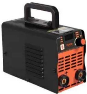
natural_image
Black and orange portable electronic device with ventilation grilles and a handle (no visible text or symbols)MMA-160

natural_image
Black and orange portable electronic device with control panel and buttons (no visible text or symbols)MMA-200MMA-140
HULP NODIG? NEEM CONTACT MET ONS OP!
www.vevor.com/support
natural_image
Line drawing of a portable electronic device with two cables, no text or symbols presentTIG-installatie
natural_image
Line drawing of a portable electronic device with two cables connected, no text or symbols presentLOCATIESELECTIE

ZORG ERVOOR DAT U DE LASSER BEDIENT VOLGENS DE
natural_image
Line drawing of a portable electronic device with ventilation slots and a top handle (no text or symbols)- Stroom: @110V, 30-120A instelbaar; @220V, 30-140A instelbaar Hot start:
natural_image
Black and orange portable electronic device with ventilation slots and a handle (no visible text or symbols)
natural_image
Black and orange portable electronic device with ventilation grilles and a handle (no visible text or symbols)MMA-160

natural_image
Black and orange portable electronic device with control panel and buttons (no visible text or symbols)MMA-200MMA-140
BEHÖVER HJÄLP? KONTAKTA OSS!
natural_image
Line drawing of a portable electronic device with two cables and clamps (no text or symbols)TIG installation
natural_image
Line drawing of a portable device connected to two cables, showing internal components and wiring (no text or symbols)VAL AV PLATS

SE TILL ATT ANVÄNDA SVETSEN ENLIGT
FÖLJANDE RIKTLINJER: • I områden fria
natural_image
Line drawing of a portable electronic device with ventilation slots and a top handle (no text or symbols)- Ström: @110V y30-120A justerbar; @220Vy30-140A justerbar Varmstart:
Överlagrat
$$ K = \mathrm{Id} $$
www.vevor.com/support