
52IN-2D-3K - Hardware Vevor - Free user manual and instructions
Find the device manual for free 52IN-2D-3K Vevor in PDF.
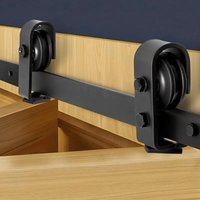


| Product Type | Sliding Barn Door Hardware Kit |
| Model | 52IN-2D-3K |
| Brand | Vevor |
| Rail Length | 1320 mm (52 inches) |
| Maximum Door Width | 610 mm (24 inches) |
| Door Thickness | 34.92 to 44.45 mm (1.375 to 1.75 inches) |
| Door Height | User Defined (H) |
| Rail to Floor Distance | H + 49 mm |
| Bottom Gap | 10 mm |
| Top Gap (Door to Ceiling) | 152 mm (6 inches) |
| Number of Doors Supported | 2 |
| Material | Steel and Plastic |
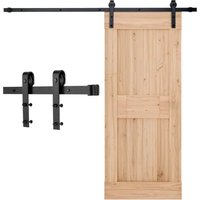
| Kit Contents | Rail, Brackets, Rollers, Hinges, Screws, Spacers, Allen Keys |
| Power Supply | Not Applicable (Manual Use) |
| Main Functions | Allows sliding of folding barn doors (bi-fold) |
| Maintenance and Cleaning | Clean with a soft dry cloth. Lubricate the rollers periodically. |
| Safety | Wear safety glasses and gloves during assembly. Keep children away. |
| Spare Parts and Repairability | Replacement parts available via www.vevor.com/support. Repair possible by a professional. |
| General Information | Original instruction manual included. Electronic warranty. |
Frequently Asked Questions - 52IN-2D-3K Vevor
User questions about 52IN-2D-3K Vevor
0 question about this device. Answer the ones you know or ask your own.
Ask a new question about this device
Download the instructions for your Hardware in PDF format for free! Find your manual 52IN-2D-3K - Vevor and take your electronic device back in hand. On this page are published all the documents necessary for the use of your device. 52IN-2D-3K by Vevor.
USER MANUAL 52IN-2D-3K Vevor
Affordable. Reliable. Home Improvement.
BIFOLD SLIDING BARN DOOR
HARDWARE KIT
Model: 36IN-3D-3K / 40IN-3D-3K / 52IN-2D-3K
Technical Support and E-Warranty Certificate
www.vevor.com/support
Model: 36IN-3D-3K / 40IN-3D-3K / 52IN-2D-3K
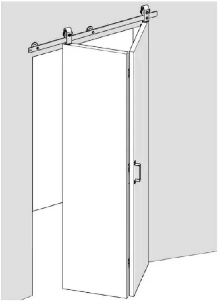
This is the original instruction. Please read all manual instructions carefully before operating. VEVOR reserves a clear interpretation of the user manual. The appearance of the product shall be subject to the product you received. Please forgive us that we won't inform you again if there are any technology or software updates on our product.
SAFETY INSTRUCTIONS
WARNING:
Read this material before using this product. Failure to do so can result in serious injury.
Assembly precautions
- Assemble only according to these instructions. Improper assembly can create hazards.
- Wear ANSI-approved safety goggles and heavy-duty work gloves during assembly. 3. Keep assembly area clean and well lit.
- Keep bystanders out of the area during assembly. 5. Do not assemble when tired or when under the influence of alcohol, drugs, or medication. 6. Product capabilities apply to properly and completely assembled products only.
- For additional information regarding the parts listed in the following pages, please refer to the Assembly Diagram of this manual. Unwrap and separate all parts in a clean work area.
- For safety reasons, this hardware is recommended to be installed by people. Products are installed away from children and pets.
Use precautions.
- This product is not a toy. Do not allow children to play with this product.
- Use as intended only.
- Inspect before every use; do not use if parts are loose or damaged.
SAVE THESE INSTRUCTIONS.
Product Suitability.
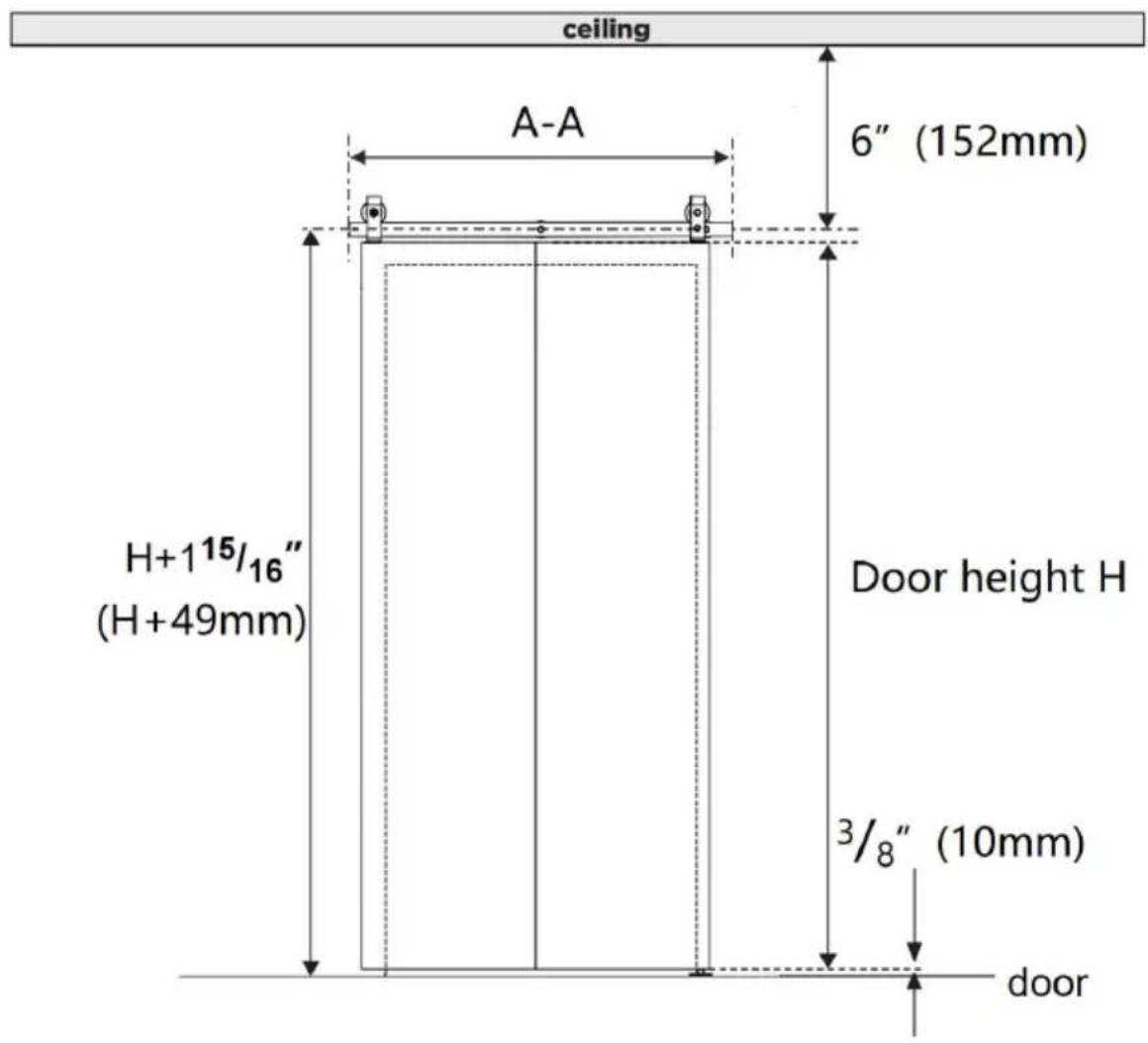
| Model | 36IN-3D-3K | 40IN-3D-3K | 52IN-2D-3K |
| rail length A-A | 36inch (914mm) | 40inch (1016mm) | 52inch (1320mm) |
| Door width | ≤16inch | ≤18inch | ≤24inch |
| Door thick | 1.375 to 1.75inches (34.92-44.45mm) | ||
| Door height | H(Depending on the user) | ||
| Distance of the rail from ground | H+49mm | ||
| Distance at the bottom of door from the ground | 10mm | ||
| Distance between the do top and the ceiling | 6inch(152mm) | ||
| quantity of doors | 2pcs | ||
The box does not contain door panels and other wooden squares, which require additional purchase.
Product decomposition diagram.
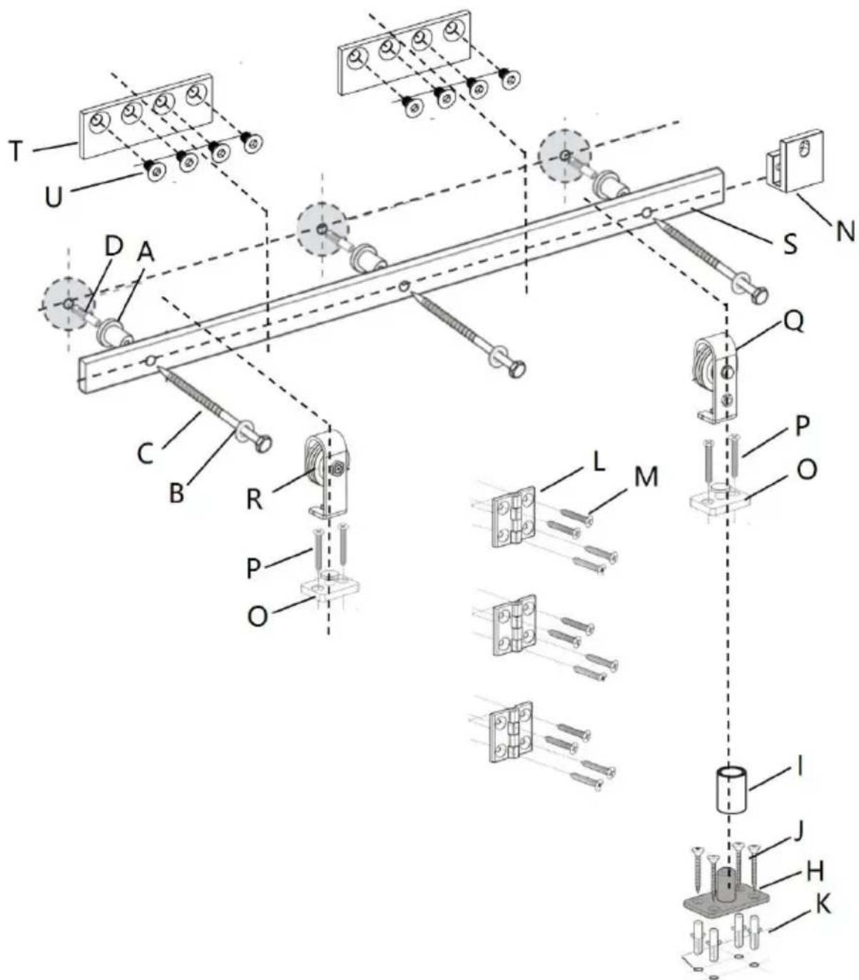
Parts list.
| Same parts of different models | |||
| A:Wall Spacer×3pcs | B:washers×3pcs | C:M8×90mm Plastic Tapping Screw×3pcs | D:φ12×50 Plastic expansion bolt×3pcs |
| E:2mm Hex Key×1pc | F 2.5mm Hex Key×1pc | G: 4mm Hex Key×1pc | H:Bottom Pivot Plate×1pc |
| I:Sleeve×1pc | J:M4×30 countersunk head tapping screw×4pcs | K:φ6×30 Plastic expansion bolt×4pcs | L:Bi-Fold Door Butt Hinges×3pcs |
| M:M6×25 countersunk head tapping screw×12pcs | N:Fixed Roller Lock Bracket×1pc | O: Roller Rotating Base×2pcs | P:M5×50 countersunk head tapping screw×4pcs |
| Q:Fixed Roller×1pc | R:Adjustable Roller×1pc | S:Rail Kit 1pc | V:Sealing Strip×1pc |
| The model 36IN-3D-3K and 40IN-3D-3K have these parts, but not available in the model 52IN-2D-3K | |||
| U:M6×10 bolt×8pcs | T:connection strap×2pcs | ||
CAUTION.
Mishandling of heavy objects (i.e., doors) may cause a loss of balance and serious injury. Always be sure you have a secure hold on the object and are balanced before moving the object. Always wear safety shoes when lifting heavy objects.
Getting body parts (i.e., hair, fingers) caught in moving parts may cause pinching and serious injury. Do not put fingers in parts that may move. Always remove or contain anything on your body that may become entangled with a moving part.
Closing doors with your hand on the end of the door may result in hand or fingers getting caught between the door and other solid objects (i.e., another door, molding) causing serious injury. Always use the door handle to close the door.
Usage Statement
Use of excessive force when opening and closing the door(s) may cause damage to the hardware. Always hold the handle to gently move the door(s).
Tools required
| Speed Square | Pencil | Phillips Screwdriver | Tape |
| Wrench | Level | Drill | Φ19/32"Drill Bit |
| Φ29/64"Drill Bit | Φ7/32"Drill Bit | Φ3/16"Drill Bit |
Product Assembly
It is very important to determine whether you need to install a HeadBoard before you install the track.
If you meet the following situations, we highly recommend using a header board (these situations might include but are not limited to):
- there is a doorway trim (like a door frame or a skirting line)
- the wall is not a concrete wall, such as drywall or other type of wall
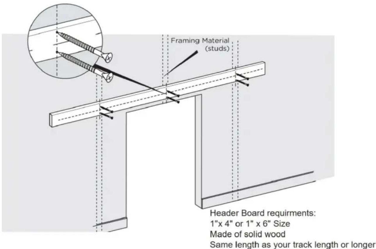
Attention: Header Board & the screws to install the header board are not included. You can buy them online or offline.
Step-1
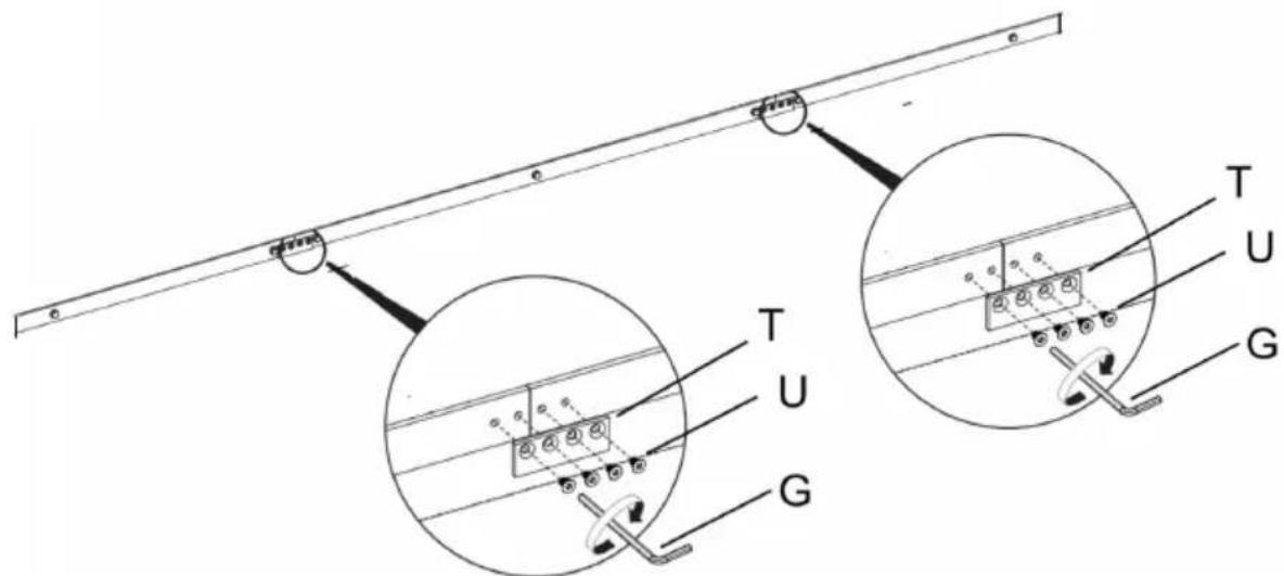
1.1. Tighten screw U with Hex Key G to connect connection strap T rails; complete the connection of the guide rail. This installation method is suitable for the guide rail of the model 36IN-3D-3K and 40IN-3D-3K.
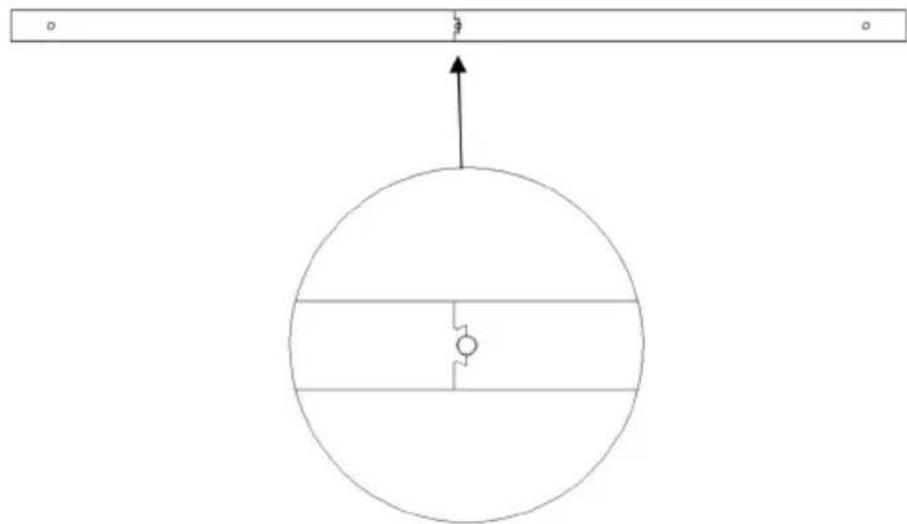
1.2. The rail of the model 52IN-2D-3K is a 2-segment rail spliced by shape.
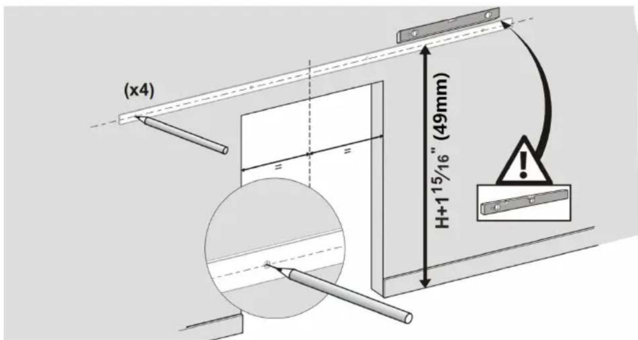
1.3. Use a Level and Tape Measure to mark the center line of the track as shown in the product selection diagram. The height of the door is H in the picture above. The height of the center line (measuring up from the floor) is the height of your door PLUS 115/16".
1.4. Position the track in place by the marked center line, ensuring it is aligned, and use the track as a template to mark the mounting hole locations for the track with a pencil. You can also refer to the track size to mark the position of the rail holes.
See installation tip below.

| Model | 36IN-3D-3K | 40IN-3D-3K | 52IN-2D-3K |
| rail length A-A | 36inch(9140mm) | 40inch(1016mm) | 52inch(1320mm) |
| rail hole distance B-B | 406mm | 457mm | 600mm |
| rail hole distance C-C | 51mm | 51mm | 60mm |
We suggest that the center of the track is at the center of the wall.
Step-2:
2.1. Use a Φ 29/64 drill to drill holes in the marked positions, 2 inches deep.
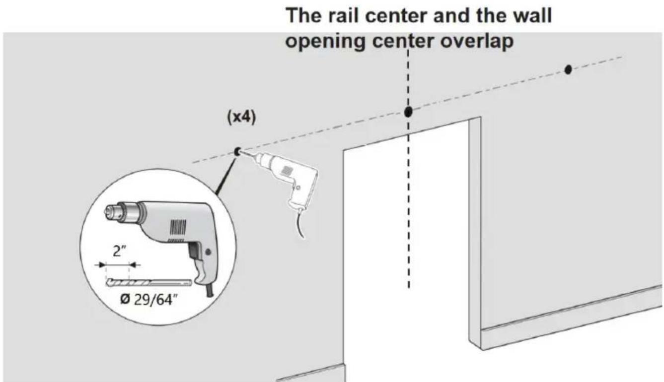
Step-3: Install the guide rail.
3.1. Install the plastic expansion bolt D into the holes on the concrete wall first. Then use screw P through the washers B, rail S, and wall spacer, and finally lock onto plastic expansion bolt D.
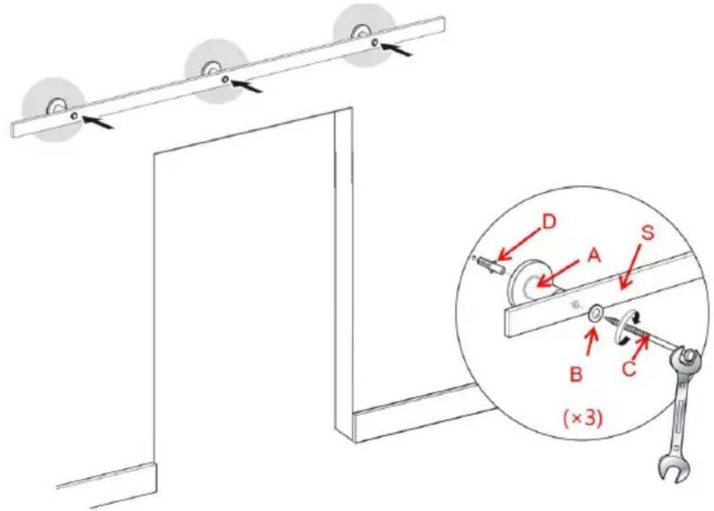
Step-4:
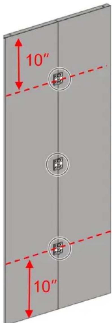
4.1. First, splice the door together. Use the Bi-Fold Door Butt Hinges hole in the door to determine the position of the screw, and mark it. Then, with a Φ 3/16" drill, drill a hole with a depth of 1 inch.
4.2. Screw M holds the Bi-Fold Door Butt Hinges L to the door. Complete assembly of the door.
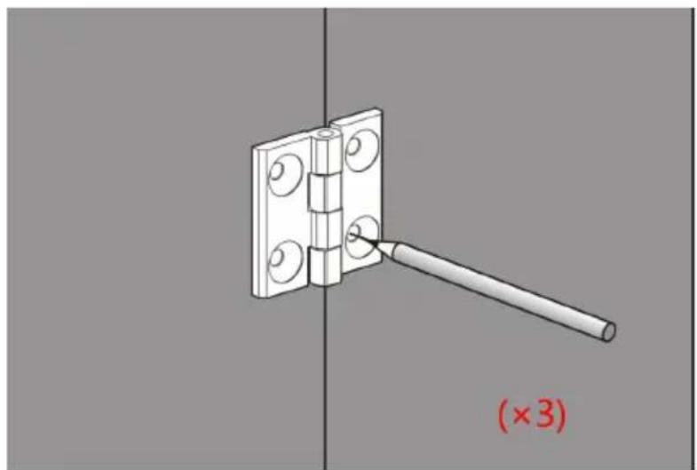
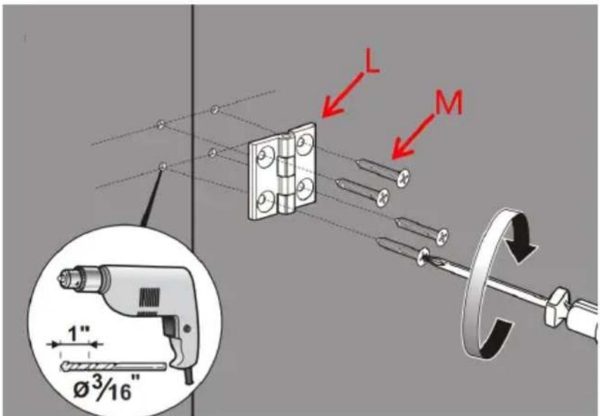
Step-5:
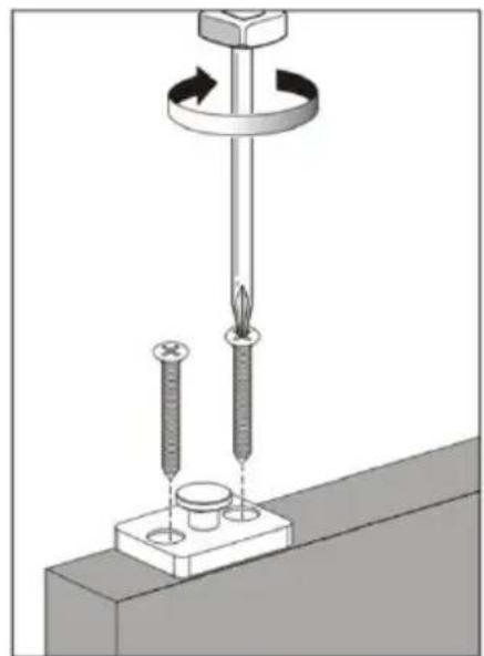
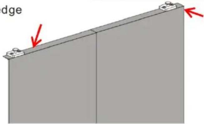
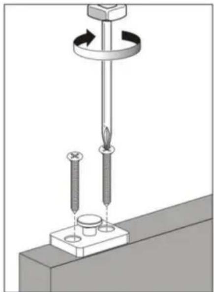
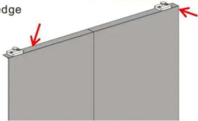
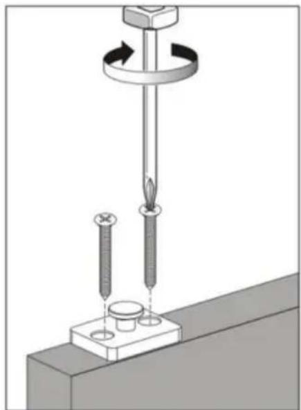
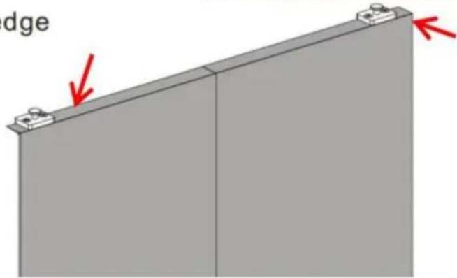
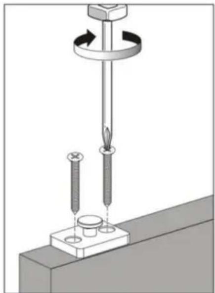
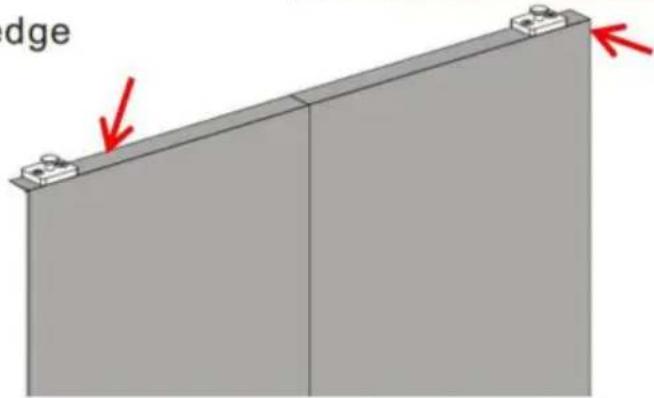
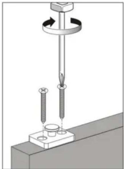
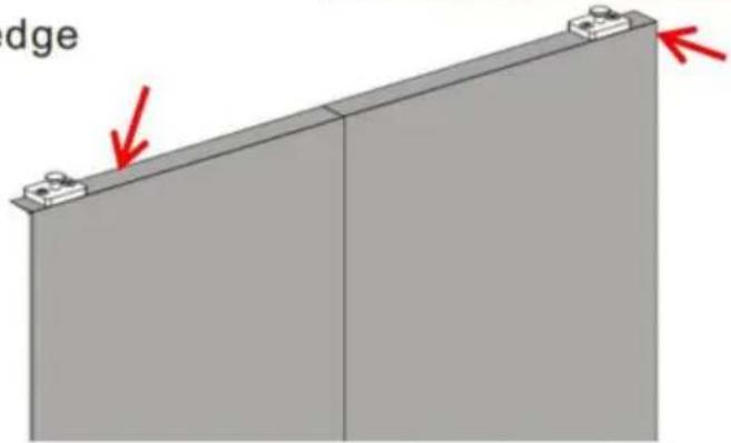
Using screw P, install 2 Roller Rotating Base O on the top of the door. The center of Roller Rotating Base O is 35mm from the edge of the door.
Distance of base center from the edge of door is 1 3/8" (35mm).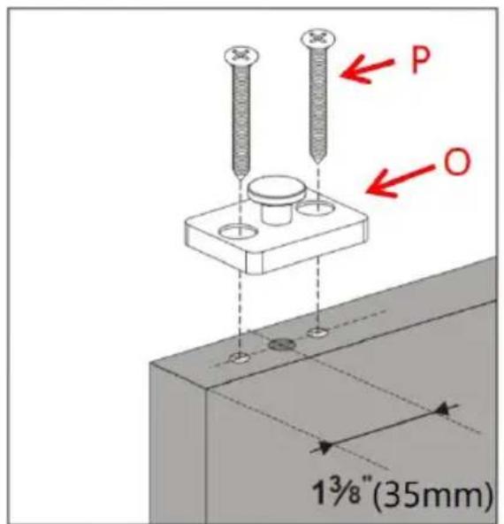
Step-6:
6.1. Drill holes with a depth of 23mm on the side of the door using a Φ 19/32 drill. The center of the hole is located 35mm away from the door edge. 6.2. Fill Sleeve I into the hole.
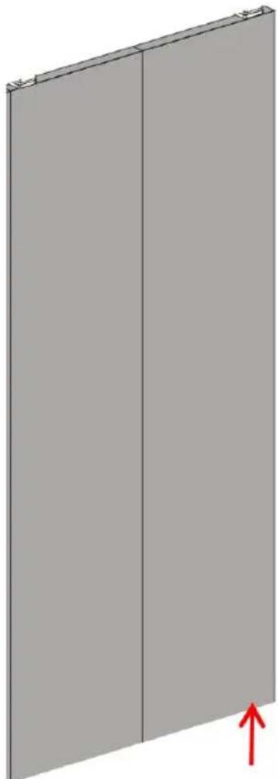
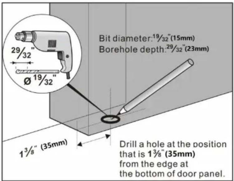
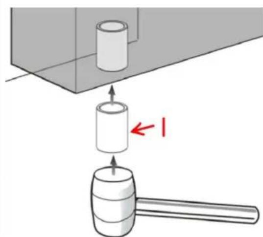
Step-7
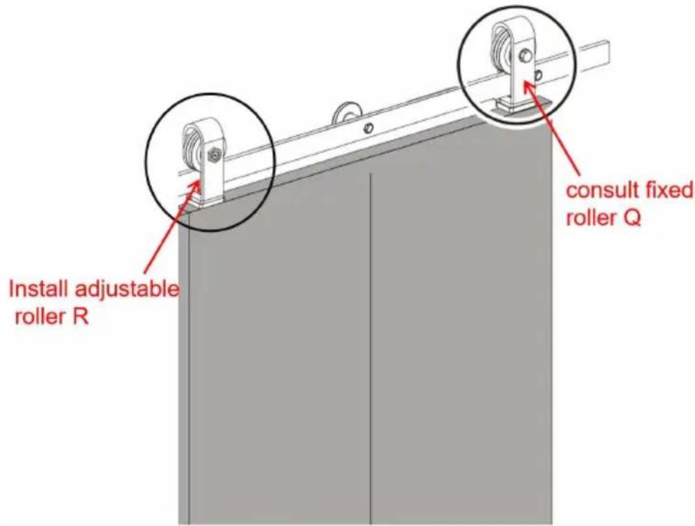
7.1. Hang the Fixed Roller Q and Adjustable Roller R on the rail.
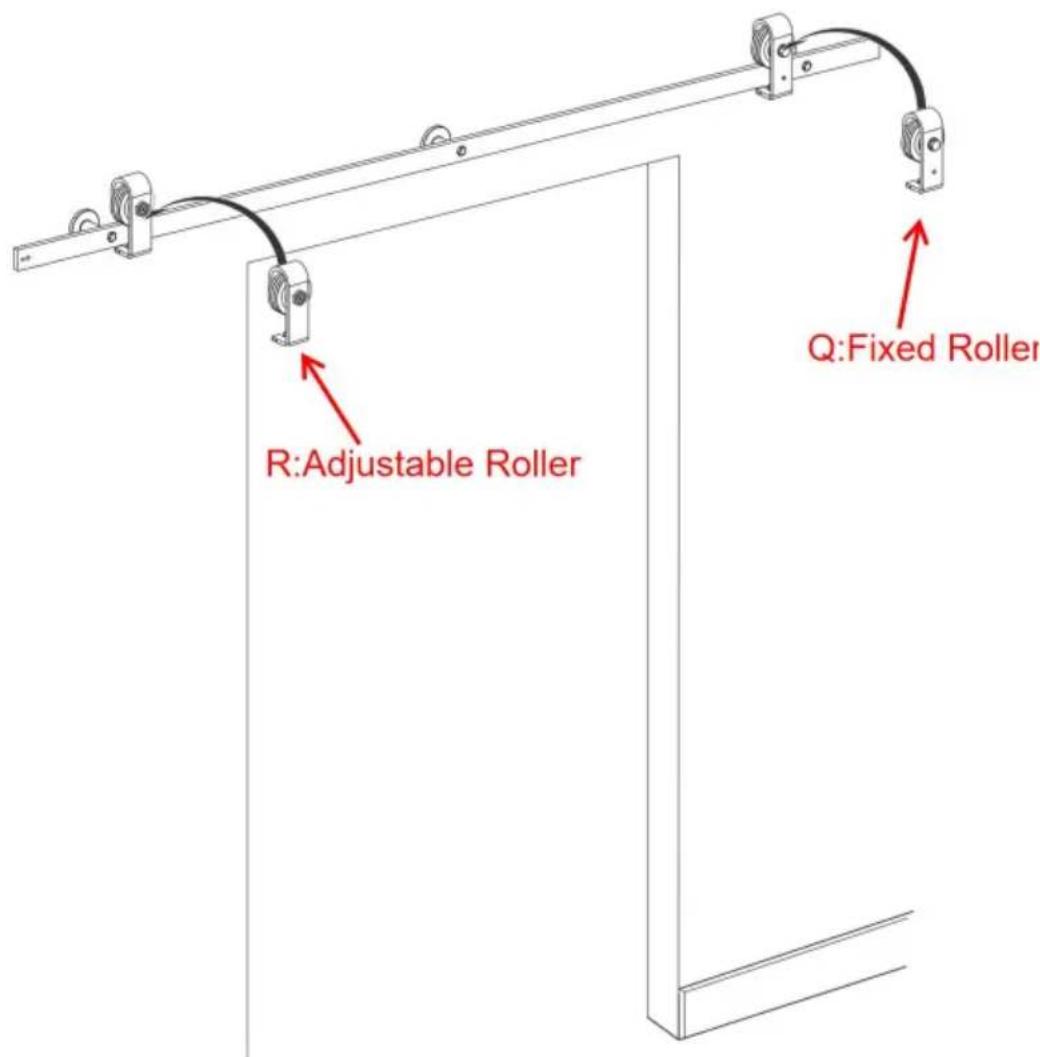
Step-8
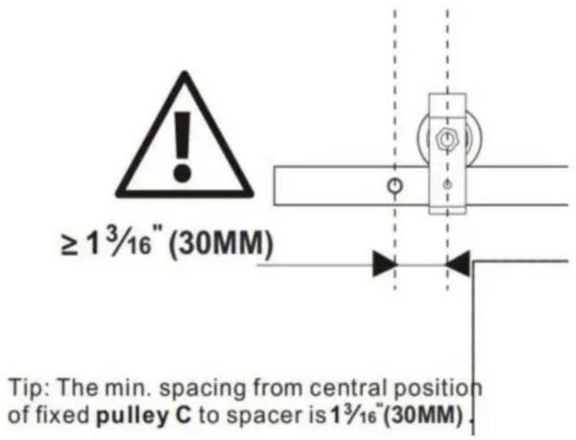
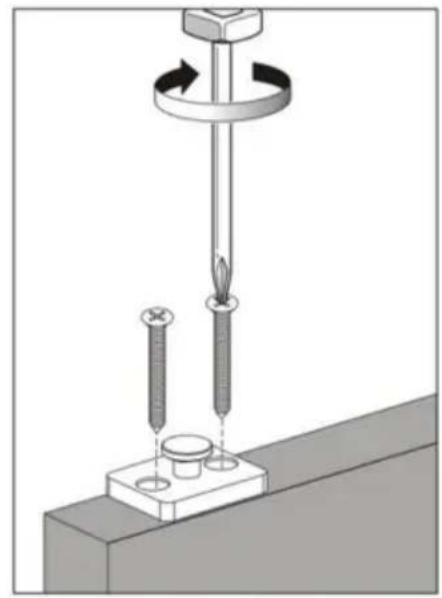
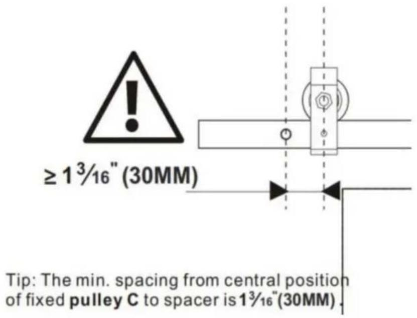
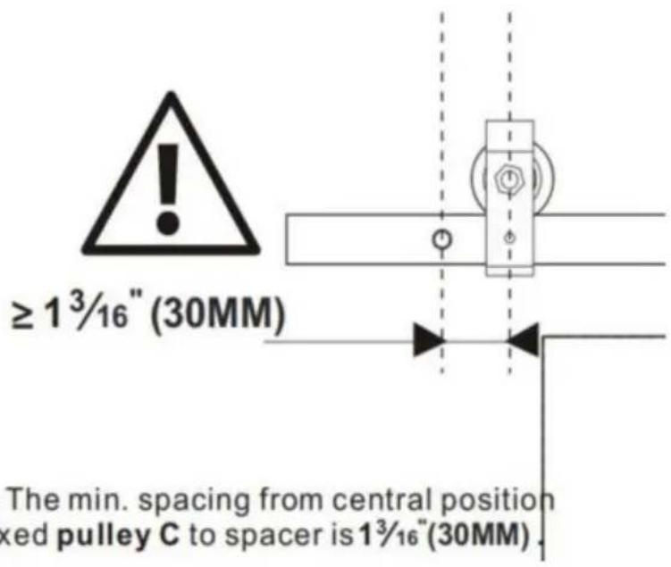
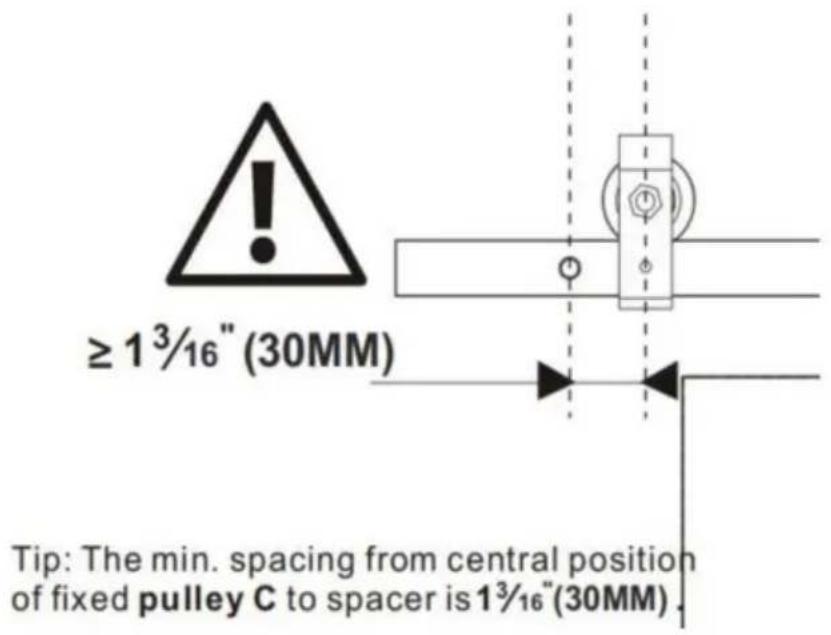
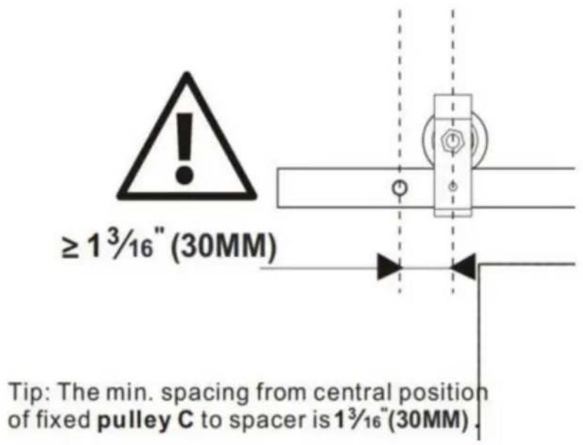
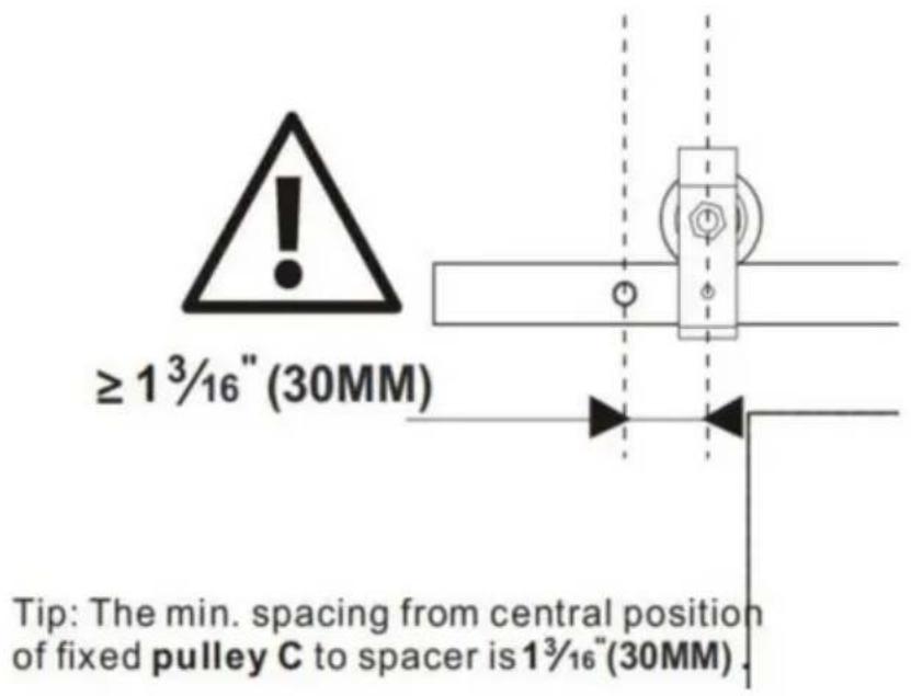
8.1. Install Bottom Pivot Plate H. Assuming the width of a single door is L, the distance between the bottom pivot plate H and the central axis wall opening is L-35mm; the distance of Bottom Pivot Plate H center in the wall is 47.6mm. 8.2. Four spots were marked above the ground with the through-hole c Bottom Pivot Plate H; drill depth 35mm holes in the mark with a 7 / 32'' drill; then insert Plastic expansion bolt k into the holes. 8.3. Attach the Bottom Pivot Plate H to the floor using a screw J. 8.4. The distance between the center of Fixed Roller Q and the outer of the track is not less than 30mm.
Assuming that the width of the door panel is L, the distance between the floor guides is L-35mm.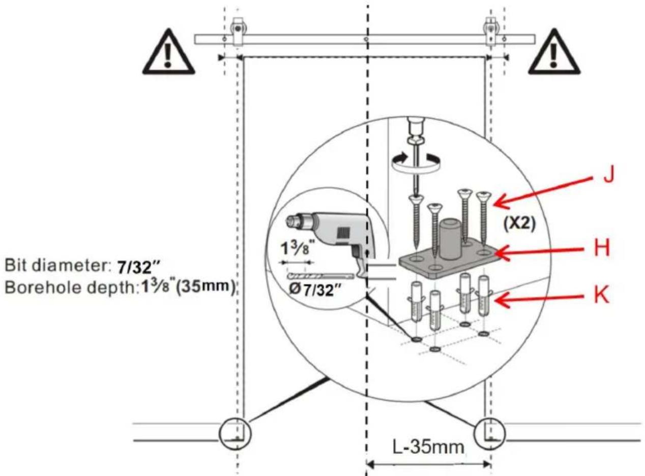
Tip: The min. spacing from central position of fixed pulley C to spacer is 13/16 (30MM).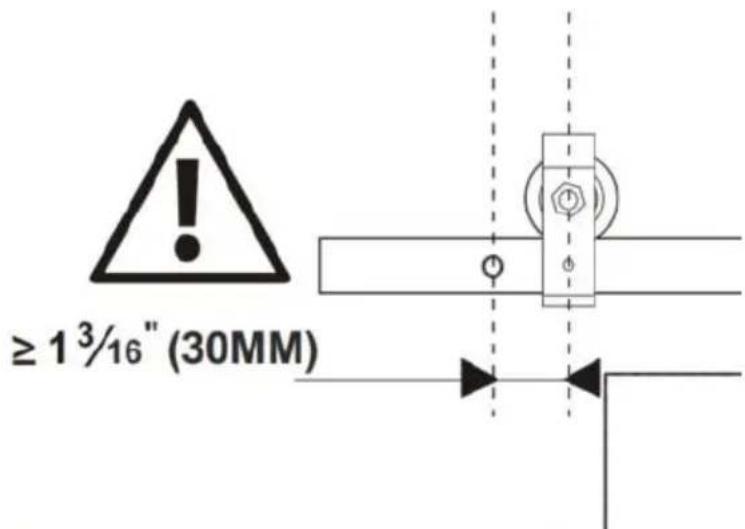
Step-9
9.1. Unscrew the set screw on the side of the fixed roller Q.
9.2. Put the door on the Sleeve I; Engage the Roller Rotating Base O on the top of the door with the fixed roller. 9.3. Tight down set screws to lock the fixed roller to the Roller Rotating Base O.
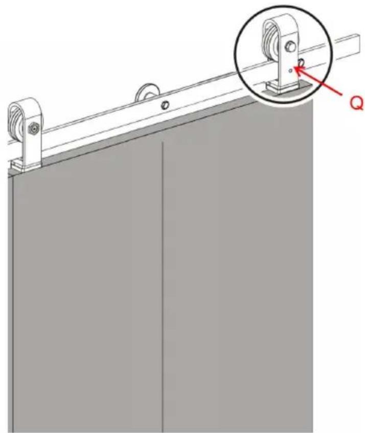
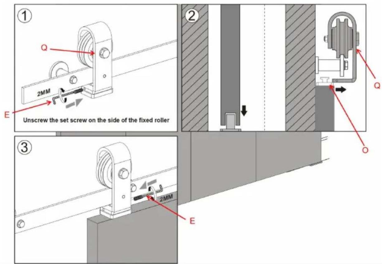
Step-10
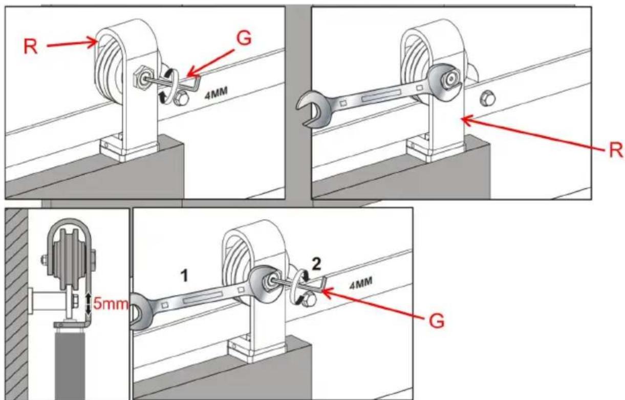
10.1. Refer to step 9, install Adjustable Roller R by the method of installing fixed roller Q. 10.2. Refer to the prompts below, adjust the height of the adjustable roller to a suitable position. Let the left and right door height be at the same level. The height of the door can be adjusted by approximately 5mm.
Step-11
Install the fixed roller lock bracket N.
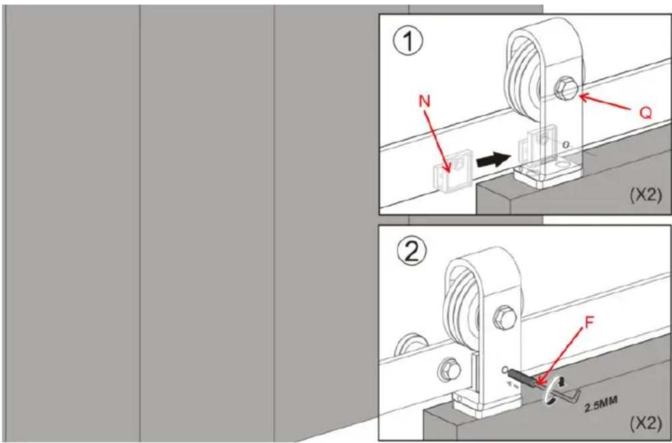
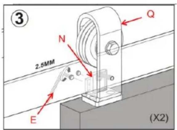
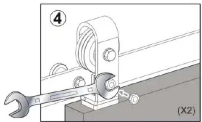
11.1. Slide the fixed roller lock bracket N onto the rail behind the set screw located on the front of the fixed roller Q. 11.2. Using the supplied Allen Wrench F, tighten the set screws on the side of the fixed roller lock bracket N. 11.3. Lock the fixed roller Q onto the rail by tightening the long set screw through the fixed roller strap lock bracket and into the rail. 11.4. Tighten the hex-head nut onto this set screw.
Manufacturer: Shanghaiuxinmuyeyouxianggsi
Address: Shuangchenglu 803nong11hao1602A-1609shi, Baoshan District, Shanghai 200000 CN.
Imported to AUS: SIHAO PTY LTD. 1 ROKEVA STREET EASTWOOD
NSW 2122 Australia
Imported to USA: Sanven Technology Ltd. Suite 250, 9166 Anaheim
Place, Rancho Cucamonga, CA 91730
| UK | REP |
YH CONSULTING LIMITED. C/O YH Consulting
Limited Office 147, Centurion House, London
Road, Staines-upon-Thames, Surrey, TW18 4A
| EC | REP |
E-CrossStu GmbH
Mainzer Landstr.69,
60329 Frankfurt am Main.

Technical Support and E-Warranty Certificate
www.vevor.com/support
VEVOR
Affordable. Reliable. Home Improvement.
TWO-PANEL SLIDING BARN DOOR
HARDWARE KIT
Model: 36IN-3D-3K/40IN-3D-3K/52IN-2D-3K
Distance of base center from the edge of door is 13/8 (35mm)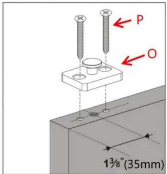
Step 6
Assuming that the width of the door panel is L, the distance between the floor guides is L-35mm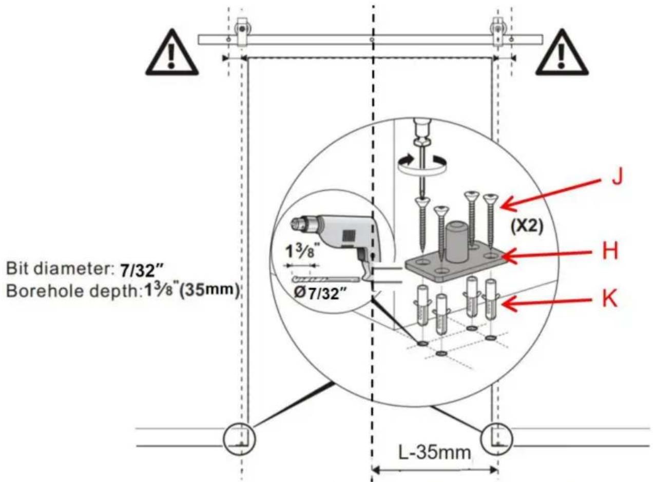
Step 9
YH CONSULTING LIMITED. C/O YH Consulting Limited Bureau 147, Centurion House, London Road, Staines-upon-Thames, Surrey, TW18 4AX
E-CrossStu GmbH
Mainzer Landstr.69,
Affordable. Reliable. Home Improvement.
FOLDING SLIDING DOOR
HARDWARE KIT
Model: 36IN-3D-3K/40IN-3D-3K/52IN-2D-3K
www.vevor.com/support
VEVOR®
TOUGH TOOLS, HALF PRICE
Distance of base center from the edge of door is 1 3/8" (35mm)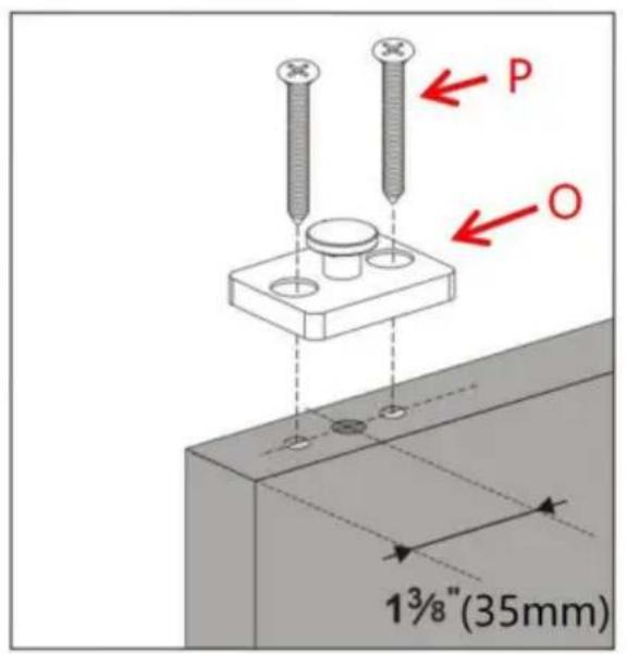

Step
Assuming that the width of the door panel is L, the distance between the floor guides is L-35mm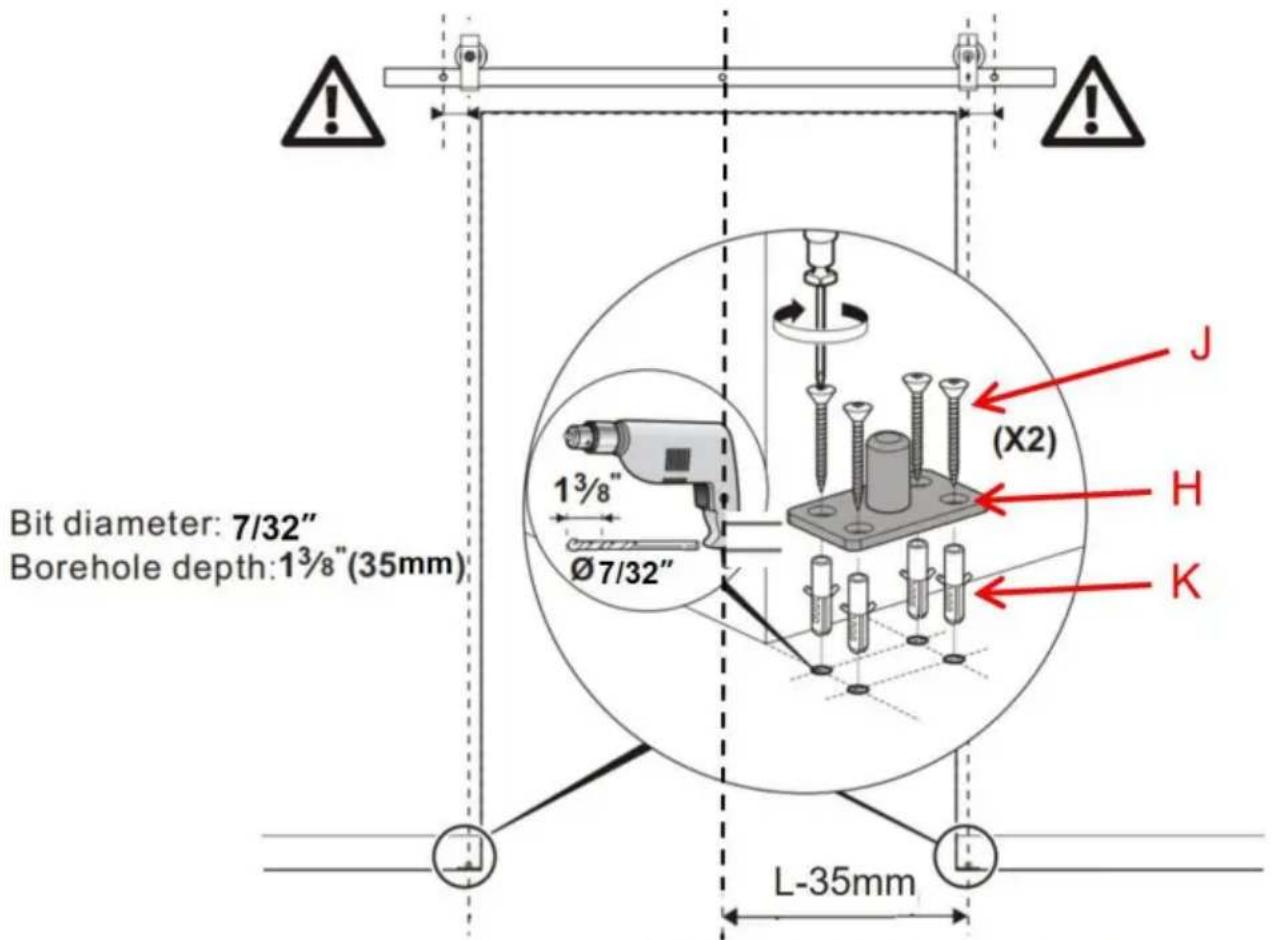
Step 9
YH CONSULTING LIMITED. C/O YH Consulting Limited Office 147, Centurion House, London Road, Staines-upon-Thames, Surrey, TW18 4AX
Affordable. Reliable. Home Improvement.
FOLDING SLIDING DOOR
TOOL KIT
Model: 36IN-3D-3K/40IN-3D-3K/52IN-2D-3K
electronics www.vevor.com/support
VEVOR®
TOUGH TOOLS, HALF PRICE
Distance of base center from the edge of door is 1 3/8" (35mm)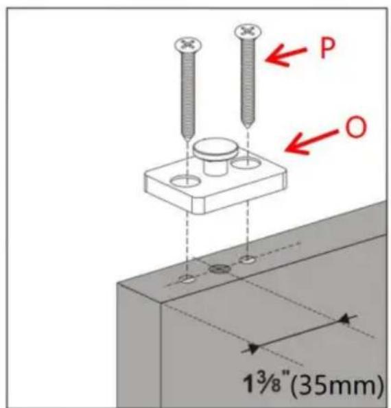
Step 6
Assuming that the width of the door panel is L, the distance between the floor guides is L-35mm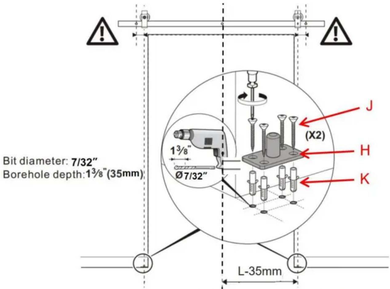
Step 9
Imported in AUS: SIHAO PTY LTD. 1 ROKEVA STREETEASTWOOD NSW 2122 Australia
Imported in USA: Sanven Technology Ltd. Suite 250, 9166 Anaheim Place, Rancho Cucamonga, CA 91730
YH CONSULTING LIMITED. C/O YH Consulting Limited Office 147, Centurion House, London Road, Staines-upon-Thames, Surrey, TW18 4AX
E-CrossStu GmbH Mainzer Landstr.69, 60329 Frankfurt am Main.

Affordable. Reliable. Home Improvement.
Distance of base center from the edge of door is 13/8 (35mm)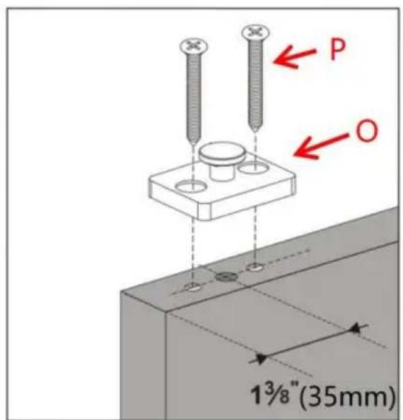
Step 6
Assuming that the width of the door panel is L, the distance between the floor guides is L-35mm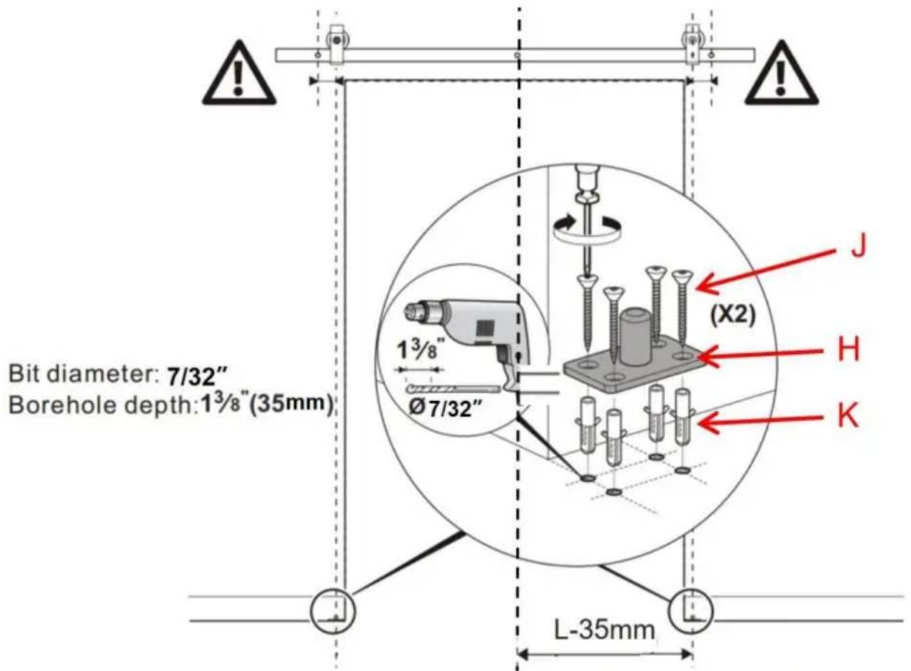
Step 9
Road, Staines-upon-Thames, Surrey, TW18 4AX
E-CrossStu GmbH
Mainzer Landstr.69,
Affordable. Reliable. Home Improvement.
SLIDING DOOR HARDWARE FOR BARN DOORS
HARDWARE KIT
Model:36IN-3D-3K/40IN-3D-3K/52IN-2D-3K
Distance of base center from the edge of door is 13/8" (35mm)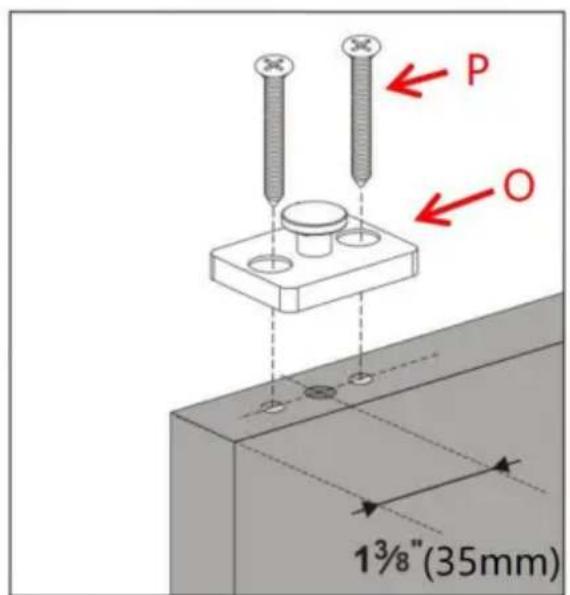
Step 6
Assuming that the width of the door panel is L, the distance between the floor guides is L-35mm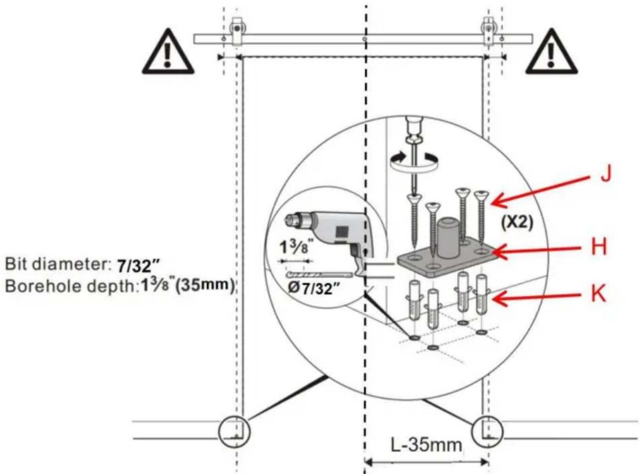
Step 9
9.1. Unscrew the locking screw located on the side of the fixed roller Q.
YH CONSULTING LIMITED. C/O YH Consulting Limited Office
147, Centurion House, London Road, Staines-upon
Thames, Surrey, TW18 4AX
| Przedstawciel UE |
E-CrossStu GmbH
Mainzer Landstr.69,
60329 Frankfurt am Main.

Affordable. Reliable. Home Improvement.
Sliding door with double sliding door
Hardware kit
Model: 36IN-3D-3K/40IN-3D-3K/52IN-2D-3K
www.vevor.com/support
VEVOR
TOUGH TOOLS, HALF PRICE
Distance of base center from the edge of door is 13/8 (35mm)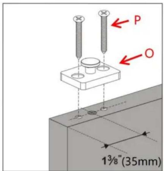
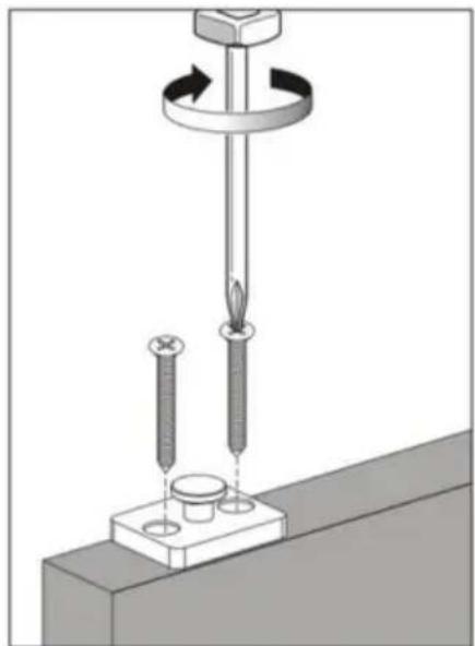
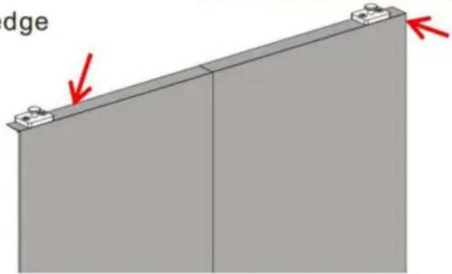
Step 6
Assuming that the width of the door panel is L, the distance between the floor guides is L-35mm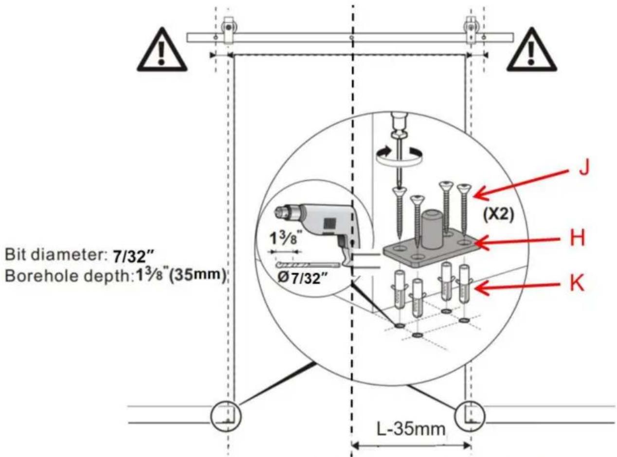
Step 9
YH CONSULTING LIMITED. C/O YH Consulting Limited Kantoor 147, Centurion House, London Road, Staines upon-Thames, Surrey, TW18 4AX

E-CrossStu GmbH
Mainzer Landstr.69,
60329 Frankfurt am Main.

Technical support and e-warranty certificate www.vevor.com/support
VEVOR
Affordable. Reliable. Home Improvement.
BIFOLD SLIDING DOOR
HARDWARE KIT
Model: 36IN-3D-3K/40IN-3D-3K/52IN-2D-3K
www.vevor.com/support
VEVOR®
TOUGH TOOLS, HALF PRICE
Distance of base center from the edge of door is 13/8" (35mm)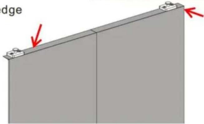
Step-6
Assuming that the width of the door panel is L, the distance between the floor guides is L-35mm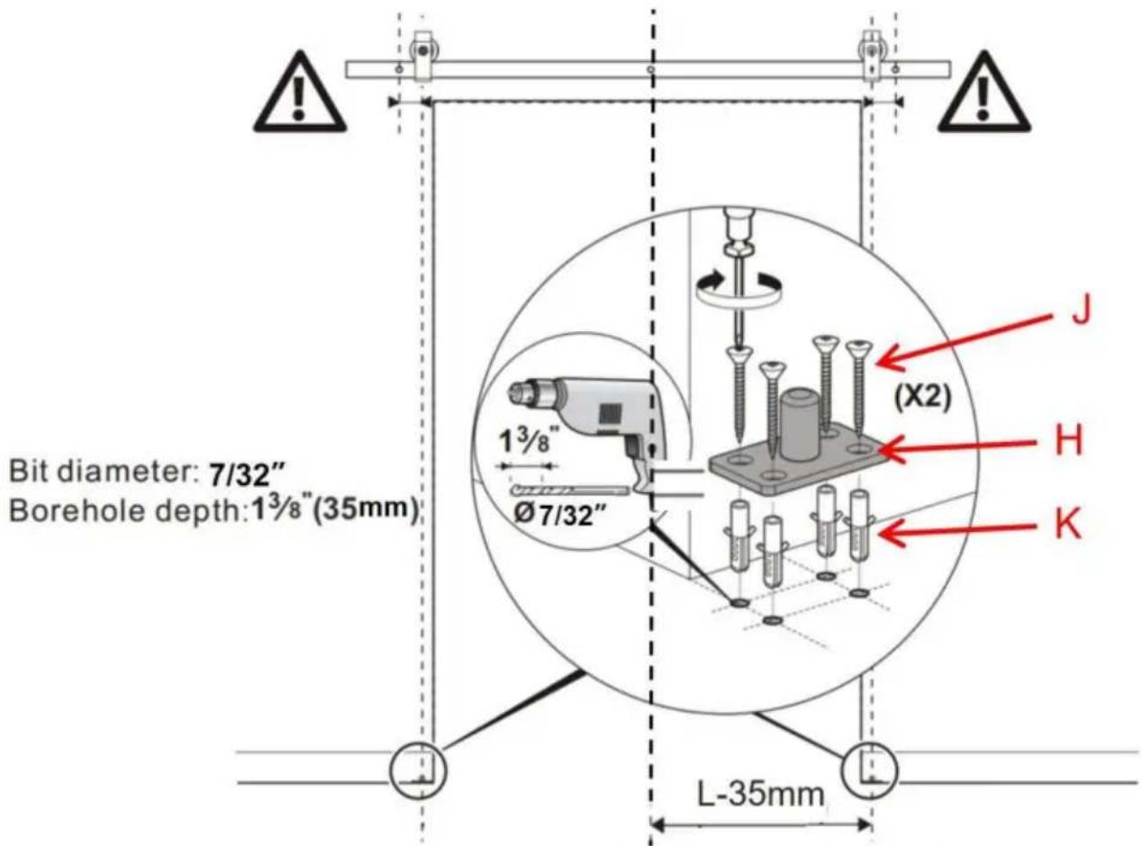
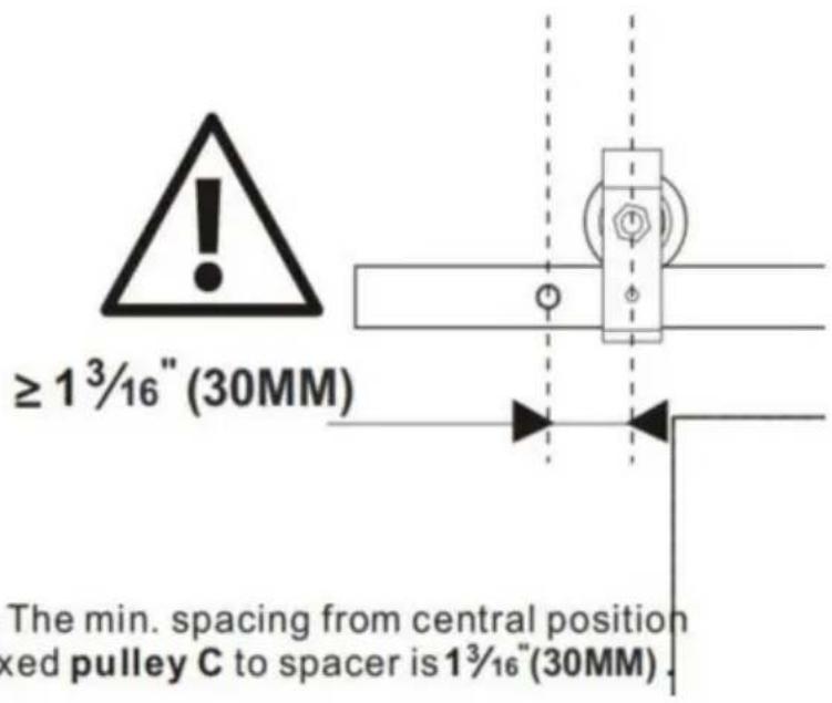
Step-9
YH CONSULTING LIMITED. C/O YH Consulting Limited Office 147, Centurion House, London Road, Staines-upon-Thames, Surrey, TW18 4AX
www.vevor.com/support
- BIFOLD SLIDING BARN DOOR
- HARDWARE KIT
- SAFETY INSTRUCTIONS
- WARNING
- ASSEMBLY PRECAUTIONS
- USE PRECAUTIONS
- SAVE THESE INSTRUCTIONS
- PRODUCT SUITABILITY
- PRODUCT DECOMPOSITION DIAGRAM
- PARTS LIST
- CAUTION
- USAGE STATEMENT
- TOOLS REQUIRED
- PRODUCT ASSEMBLY
- STEP
- VEVOR
- AFFORDABLE. RELIABLE. HOME IMPROVEMENT
- FOLDING SLIDING DOOR
- MODEL: 36IN-3D-3K/40IN-3D-3K/52IN-2D-3K
- VEVOR®
- TOOL KIT
- SLIDING DOOR WITH DOUBLE SLIDING DOOR
Brand : Vevor
Model : 52IN-2D-3K
Category : Hardware