KQ-1.5K - Pump Vevor - Free user manual and instructions
Find the device manual for free KQ-1.5K Vevor in PDF.

User questions about KQ-1.5K Vevor
0 question about this device. Answer the ones you know or ask your own.
Ask a new question about this device
Download the instructions for your Pump in PDF format for free! Find your manual KQ-1.5K - Vevor and take your electronic device back in hand. On this page are published all the documents necessary for the use of your device. KQ-1.5K by Vevor.
USER MANUAL KQ-1.5K Vevor
Technical Support and E-Warranty Certificate www.vevor.com/support
We continue to be committed to provide you tools with competitive price. "Save Half", "Half Price" or any other similar expressions used by us only represent of savings you might benefit from buying certain tools with us compared top brands and does not necessarily mean to cover all categories of tools offered are kindly reminded to verify carefully when you are placing an order with us actually saving half in comparison with the top major brands.
VEVOR®
TOUGH TOOLS, HALF PRICE
VACUUM PUMP MANIFOLD GAUGE SET
PUMP MODEL: KQ-1K

natural_image
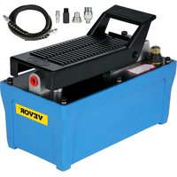
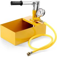
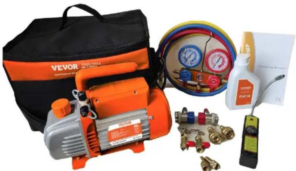
Product photo of Vevor air pressure pump and gas distribution system (no visible text or symbols)CE
NEED HELP? CONTACT US!
Have product questions? Need technical support? Please feel fr contact us:
Technical Support and E-Warranty Certificate www.vevor.com/support
This is the original instruction, please read all manual instruction carefully before operating. VEVOR reserves a clear interpretation user manual. The appearance of the product shall be subject to product you received. Please forgive us that we won't inform you there are any technology or software updates on our product.
This product is subject to the provision of European Directive 2012/19/EU. The symbol showing a wheelie bin crossed through indicates that the product requires separate refuse collection in European Union. This applies to the product and all accessories marked with this symbol. Products marked as such may not be discawith normal domestic waste but must be taken to a collection point 1 recycling electrical and electronic devices.
INTRODUCTION
Welcome to the user manual for your Vacuum Pump and Gauge Kit, designed to assist you in maintaining your AC system. This tool kit is a vacuum pump, vacuum gauge, hoses, and adapters and is essential vacuuming and recharging the refrigerant in your AC system.
This user manual has been developed to provide you with comprehen guidance on how to use the tool kit. We will explain the key feature components of the kit, as well as provide important safety guidelines help you avoid potential risks or damage during maintenance.
Please note that this is a basic user guide for AC maintenance scene. We recommend that you familiarize yourself with the operation of AC maintenance and have sufficient knowledge to avoid damage or injury.
By following the instructions and guidelines in this user manual, you ensure the safe and effective use of your vacuum pump kit and maintain repair your AC system to guarantee optimal performance.
Please note that while this user manual provides important warnings, precautions, and instructions for using the vacuum pump and gauge k cannot anticipate every possible situation or condition that may arise during use. It is important for the operator to exercise good judgment common sense, and caution while handling the product. These factors cannot be built into the product but must be supplied by the operato
Safety guidelines for handling your vacuum pump
◆ To ensure the safe and proper use of this kit, it is important to it is designed only for vacuuming air or small amounts of residual refrigerant. It should not be used to remove refrigerant directly from AC system.
If refrigerant recovery is required, a recovery machine is strongly recommended. Using a vacuum pump and recovery tank to recover refrigerant without a recovery machine should only be operated by trained and certificated AC technician.
Electrical shock hazard: Do not touch the vacuum pump with wet hands or while standing on a wet surface. Always use the vacuum pump in a dry environment and plug it into a properly grounded
◆ Fire hazard: Do not use the vacuum pump near flammable or combustible materials. Keep the pump away from sources of heat sparks, such as flames, cigarettes, or electrical appliances.
◆ Explosion hazard: Do not use the vacuum pump with gases that a flammable, explosive, or poisonous. Always check the safety data sheet (SDS) of the gas before using it with the vacuum pump. Additionally, do not exceed the specified pressure range for the p
◆ Corrosion hazard: Do not use the vacuum pump with gases that correlate metals or exert chemical charges. Check the compatibility the gas with the materials of the pump and its accessories. Always protective gloves and eyewear when handling corrosive materials.
◆ Never operate the pump without oil, as this can damage the pump
create potential hazards.
◆ The temperature of the pumped gas should not exceed 80^ C, and environment temperature should be around 5^ C to 60^ C. This will prevent damage to the pump and ensure safe operation.
When unplugging the pump, always pull the plug. Do not unplug the unit by pulling on the wire, as this can cause damage to the cc create potential hazards.
◆ Do not use a damaged plug or outlet, as this can cause electrical shock or fire.
Safety guidelines for handling the gauge set
◆ Wear appropriate personal protective equipment (PPE), such as safe glasses and gloves, when using the gauge set. This is especially important when handling refrigerant, which can cause skin and eye irritation and can be harmful if inhaled.
◆ Ensure that the gauge set is properly connected and secured before use. Loose connections can lead to leaks, which can cause the refrigerant to escape into the environment and create a hazardous situation.
◆ Always use the gauge set in a well-ventilated area. This is important to avoid the buildup of refrigerant vapors, which can displace oxygen create a suffocation hazard. If you feel dizzy or lightheaded while the gauge set, move to a well-ventilated area immediately.
Do not exceed the maximum pressure rating of the gauge set and hoses. This information should be clearly labeled on the gauge its in the user manual. Exceeding the maximum pressure rating can cause the gauge to malfunction or even rupture, leading to potent hazards.
◆ Service hoses can not withstand high temperatures or severe mechanical stress. Keep the service hoses away from moving or engine parts. Service hoses can split or burst, causing injury.
◆ Never use the gauge set for purposes other than those specified manual. Using the gauge set for other applications can result in damage to the equipment, potential injury, or other hazards.
Introducing the vacuum pump and gauge set series
The product series includes 4 SKUs, with each vacuum pump and gas set designed for different user scenarios and intended purposes based the explosion-proof performance of the pump and accessories.
SKU1: 3.5 CFM Kit for AC is designed for maintaining most home/ve AC or refrigerant systems using A1 refrigerant. However, it should not used for maintaining AC systems with R32, R1234yf, or other A2L or above-level refrigerants.
SKU2: 4 CFM Kit for new AC is designed for maintaining most AC refrigerant systems, and due to its spark-less design, it can also be maintain AC systems with R32, R1234yf (quick connect adapter not included), or other A2L level refrigerants, as well as all A1 level refri systems.
SKU3: 4 CFM Kit for AC with leak detector is designed for maintain most AC or refrigerant systems using A1 refrigerant and includes a lead detector to help the operator find the leak point of the system.
SKU4: 3.5 CFM Kit for new vehicle AC is designed for maintaining home/vehicle AC or refrigerant systems using A1 refrigerant, as well as systems using A2L refrigerant due to its spark-less design. It comes R134a quick connectors and R1234yf adapters to make it applicable for both old and newly manufactured vehicles.
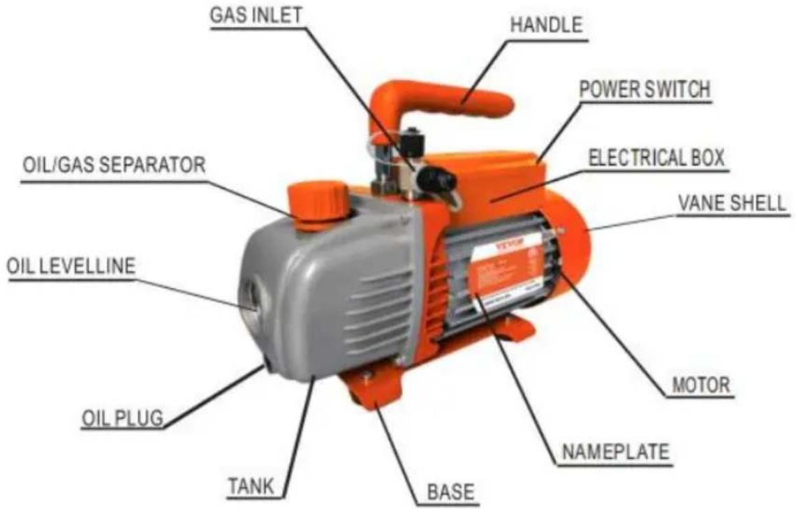
Explanation of the vacuum pump's components and specification
| Model | KQ-1K | KQ-1.5K | KQ-1K | KQ-1.5K | |||||
| Voltage | 120V/60Hz | 220-240V/50Hz | 120V/60Hz | 220-240V/50Hz | 120V/60Hz | 220-240V/50Hz | 120V/60Hz | 220-240V/50Hz | |
| Free Air Displacement | CFM | 3.5 | 3.5 | 4 | 4 | 3.5 | 3.5 | 4 | 4 |
| Ultimate Vacuum | Pa | 8 | 8 | 8 | 8 | 8 | 8 | 8 | 8 |
| Motor | HP | 1/5 | 1/5 | 1/4 | 1/4 | 1/5 | 1/5 | 1/4 | 1/4 |
| Intake Fitting | 1/4"SAE male; 1/2"ACME male; | 1/4"SAE male; 1/2"ACME male; | 1/4"SAE male; 1/2"ACME male; | 1/4"SAE male; 1/2"ACME male; | 1/4"SAE male; 1/2"ACME male; | 1/4"SAE male; 1/2"ACME male; | 1/4"SAE male;1/2"ACME male; | 1/4"SAE male; 1/2"ACME male; | |
| Oil Capacity | ml | 250 | 250 | 200 | 200 | 250 | 250 | 200 | 200 |
| Dimensions | mm | 290*120*220 | 290*120*220 | 305*110*220 | 305*110*220 | 290*120*220 | 290*120*220 | 305*110*220 | 305*110*220 |
| Net Weight | Kg | 5.5 | 5.4 | 5.8 | 5.8 | 5.5 | 5.4 | 5.8 | 5.8 |
| Applicable Refrigerant | R134a, R22, R410A and any other A1 refrigerants | R32, R1234yf, R134a, R22, R410A, and any other A1 refrigerants | |||||||
Vacuum pump manifold gauge set package contents
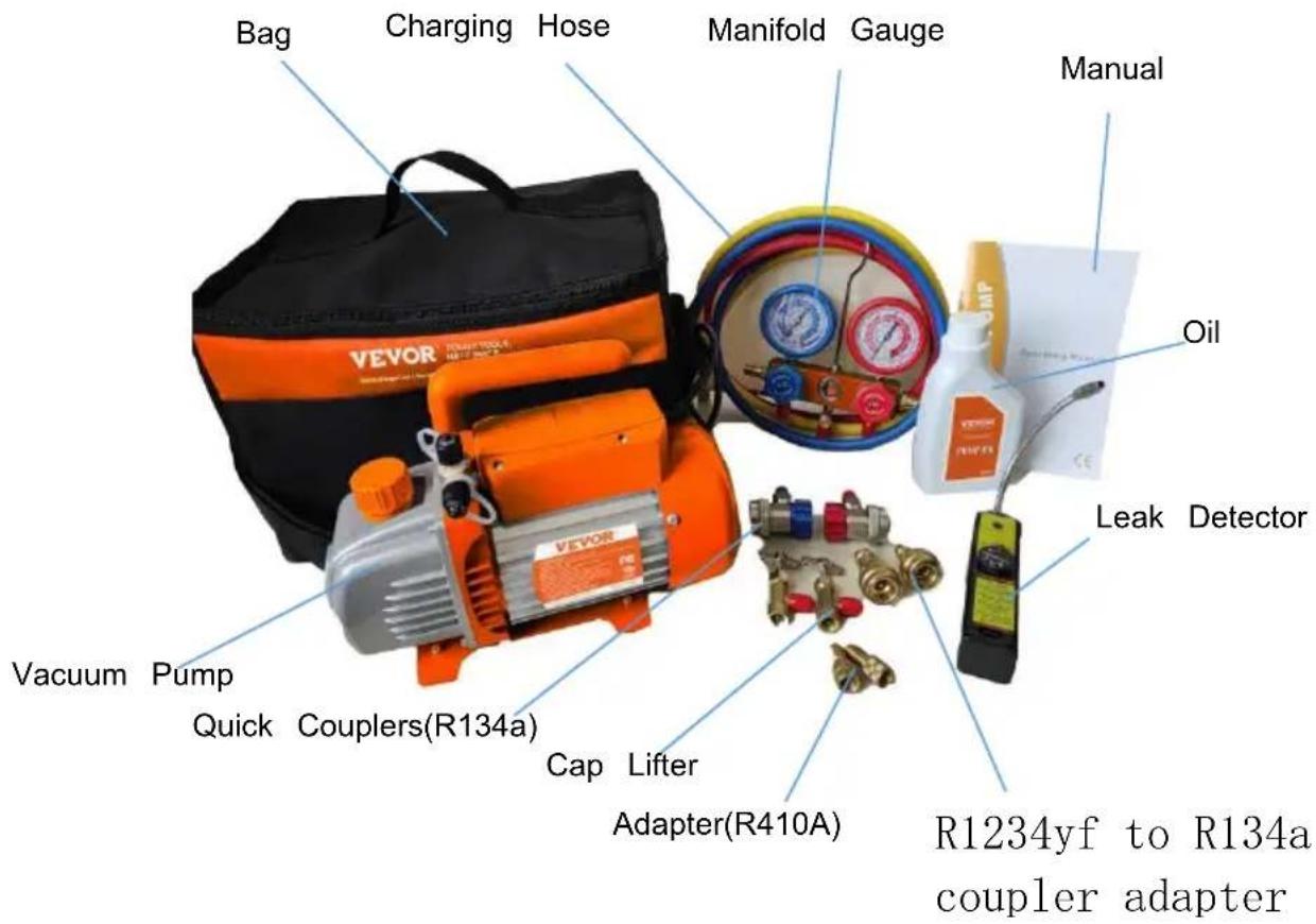
Package Content List
| Set Name | 3.5 CFM Kit fo AC | 4 CFM Kit fo new AC | 4 CFM Kit for | 3.5 CFM Kit fo new vehicle AC |
| Packing List | 3.5CFM Vacuum Pumpx1Manifold Gaugex1Charging Hosex3R410A Adapter x2R134a Cap Lifterx1Bagx1R134a QuickCouplers (High And Low Pressure) x1Vacuum Pump Oilx1Manualx1 | 4CFM Vacuum Pumpx1Manifold Gaugex1Charging Hosex3R410A Adapterx2R134a Cap Lifterx1Bagx1R134a QuickCouplers (High And Low Pressure) x1Vacuum Pump Oilx1Manualx1 | 4CFM Vacuum Pumpx1Manifold Gaugex1Charging Hosex3R410A Adapter x2R134a Cap Lifterx1R134a QuickCouplers (High And Low Pressure) x1Bagx1Leak Detectorx1Vacuum Pump Oilx1Manualx1 | 3.5CFM Vacuum Pumpx1Manifold Gaugex1Charging Hosex3R410A Adapter x2R134a Cap Lifterx1R134a QuickCouplers (High And Low Pressure) x1R1234yf Cap Lifterx1Bagx1R1234yf to R134a coupler adapterx2Vacuum Pump Pilx1Manualx1 |
- Pump preparation: Insert the pump's plug, and fill it with oil, make not to exceed the maximum level.
- Locate the high and low-pressure service ports of the AC system. ports are usually situated near the compressor on the lines.
- Connect the gauge set hoses to the high and low-pressure service of the AC system. The high-pressure side is typically marked with red the low-pressure side with blue. Choose the appropriate adapter for the refrigerant system and fitting.
- Shut the valves on the gauge set and attach the hoses from the pump to the gauge set. Switch on the vacuum pump and allow it to a few minutes to ensure that it is functioning correctly.
- Open the valves on the gauge set and allow the vacuum pump to operate until the system pressure reaches approximately 30 inchHg an stabilizes. Continue pumping for at least 30 minutes to ensure that all remaining air is removed.
- Shut the valves on the gauge and switch off the vacuum pump, if the system to rest for approximately 30 minutes, as recommended, to confirm that there are no leaks. Any increase in the pressure display the gauge set implies the presence of a leak.
- Once you are convinced that there are no leaks and have attained desired vacuum level, you can either charge the refrigerant or close it valve for future use.
Proper maintenance of the vacuum pump is essential to ensure its performance. Here are some maintenance guidelines:
◆ Keep the pump clean and free from foreign matter.
◆ Keep the oil filled to the oil level, and never let the pump run w oil.
◆ Keep the oil clean. If the oil becomes dirty, muddy, or water or volatile substances get in, it will affect the performance of the pump and the oil should be replaced. To replace the oil, start the pump run it for about 30 minutes to make the oil thin. Then stop the and drain the oil from the oil drain plug. Open the gas inlet and pump for 1-2 minutes while adding a small quantity of clean oil in gas inlet. This is to replace the residual oil from the inside of the After ensuring that the pump is clean, put the drain plug back in the clean pump oil from the gas inlet to the oil level.
◆ To store the pump when not in use for long periods of time, cow oil cap and exhaust cap (if applicable) and store it in a dry plac
◆ Repair of the pump should only be done by a qualified service technician.
| Problem | Possible Cause | Correction |
| Low Degree Of Vacuum | 1. Insufficient oil | 1. Add oil up to the oil level line |
| 2. Dirty oil | 2. Replace the oil | |
| 3. Oil intake is blocked | 3. Clean the oil intake or filter | |
| 4. Hose or gas inlet is clogged | 4. Check the connecting pipes | |
| 5. Pump is unsuitable for the application | 5. Get a suitable pump for the application | |
| Oil Leaks | 1. Oil seal is damaged | 1. Replace the oil seal |
| 2. Housing gasket is loose or worn | 2. Replace the housing gasket | |
| Oil Spray | 1. Too much oil | 1. Adjust the oil level to the recommended |
| 2. Gas inlet pressure is too high of much gas has been pumped | 2. Use a bigger pump or reduce gas inlet pressure | |
| Starting Difficulty | 1. Oil temperature is too low | 1. Attempt to start the pump multiple times warm the oil |
| 2. Electrical malfunction | 2. Check and repair any electrical issues | |
| 3. Foreign matter is in the pump | 3. Check and remove any foreign matter from the pump system | |
| Failure To Pull a Good Vacuum | Leakage in vacuum gauge or connections | Confirm leakage by monitoring the vacuum gauge while applying vacuum pump oil at a connections or suspected leak points. The vacuum will improve briefly while the oil is sealing the leak. |
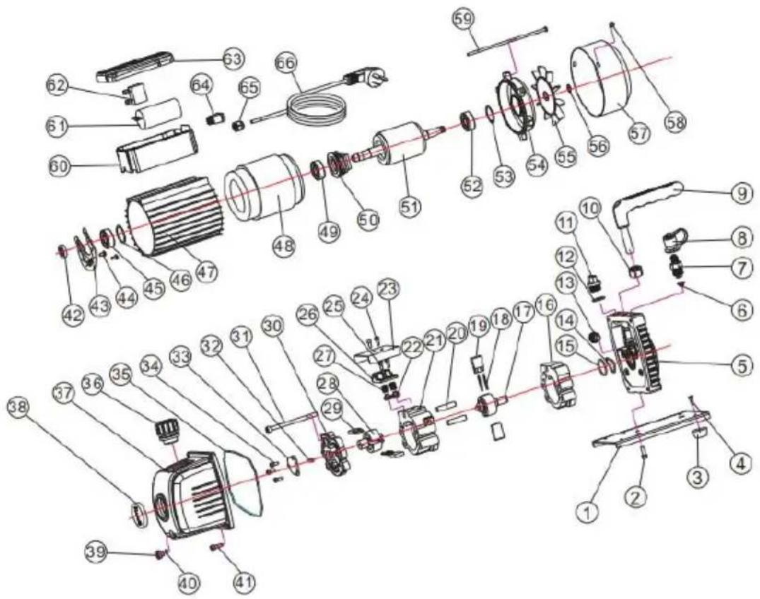
| 01 | Baseboard | 18 | Spring | 35 | O-ring | 52 | Bearing |
| 02 | Screw | 19 | Front-pump vane | 36 | Oil gas separator | 53 | Waveform gasket |
| 03 | Rubber feet | 20 | Straight pin | 37 | Oil tank | 54 | Motor back cover |
| 04 | Screw | 21 | Back-pump stator | 38 | Oil level | 55 | Fan |
| 05 | Bracket | 22 | Exhaust valve core | 39 | Oil drain plug | 56 | Snap ring |
| 06 | Stainer | 23 | Cap board | 40 | O-ring | 57 | Fan cover |
| 07 | Inlet fitting | 24 | Screw | 41 | Screw | 58 | Screw |
| 08 | Inlet fitting cap | 25 | Screw | 42 | Oil seal | 59 | Screw |
| 09 | Handle | 26 | Valve set | 43 | Centrifugal plate | 60 | Junction box base |
| 10 | Nut | 27 | Valve core spring | 44 | Screw | 61 | Capacitor |
| 11 | Oil filling port | 28 | Back-pump rotor | 45 | Bearing | 62 | Thermal protector |
| 12 | O-ring | 29 | Back-pump vane | 46 | Bearing gasket | 63 | Junction box cover |
| 13 | Gas ballast fitting | 30 | Back cover | 47 | Motor cover | 64 | Switch |
| 14 | O-ring | 31 | Screw | 48 | Motorstator components | 65 | ply-yarn drill |
| 15 | O-ring | 32 | Oil pump vane | 49 | Bearing | 66 | Power cable |
| 16 | Front-pump stator | 33 | Oil pump cover | 50 | Centrifugal | ||
| 17 | Front-pump rotor | 34 | Screw | 51 | Motor rotor components |
VEVOR®
TOUGH TOOLS, HALF PRICE
Technical Support and E-Warranty Certificate www.vevor.com/support
VEVOR®
TOUGH TOOLS, HALF PRICE
We continue to be committed to provide you tools with competitive price. "Save Half", "Half Price" or any other similar expressions used by us only represent of savings you might benefit from buying certain tools with us compared top brands and does not necessarily mean to cover all categories of tools offered are kindly reminded to verify carefully when you are placing an order with us actually saving half in comparison with the top major brands.
VEVOR®
TOUGH TOOLS, HALF PRICE
VACUUM PUMP MANIFOLD GAUGE SET
POMPE MODÈLE: KQ-1K

natural_image
Product photo of Vevor air pressure pump and gas distribution system (no visible text or symbols)CE
NEED HELP? CONTACT US!
Have product questions? Need technical support? Please feel fr contact us:
Technical Support and E-Warranty Certificate www.vevor.com/support
This is the original instruction, please read all manual instruction carefully before operating. VEVOR reserves a clear interpretation user manual. The appearance of the product shall be subject to product you received. Please forgive us that we won't inform you there are any technology or software updates on our product.

TROUBLESHOOTING GUIDE
| 01 | Baseboard | 18 | Spring | 35 | O-ring | 52 | Bearing |
| 02 | Screw | 19 | Front-pump vane | 36 | Oil gas separator | 53 | Waveform gasket |
| 03 | Rubber feet | 20 | Straight pin | 37 | Oil tank | 54 | Motor back cover |
| 04 | Screw | 21 | Back-pump stator | 38 | Oil level | 55 | Fan |
| 05 | Bracket | 22 | Exhaust valve core | 39 | Oil drain plug | 56 | Snap ring |
| 06 | Stainer | 23 | Cap board | 40 | O-ring | 57 | Fan cover |
| 07 | Inlet fitting | 24 | Screw | 41 | Screw | 58 | Screw |
| 08 | Inlet fitting cap | 25 | Screw | 42 | Oil seal | 59 | Screw |
| 09 | Handle | 26 | Valve set | 43 | Centrifugal plate | 60 | Junction box base |
| 10 | Nut | 27 | Valve core spring | 44 | Screw | 61 | Capacitor |
| 11 | Oil filling port | 28 | Back-pump rotor | 45 | Bearing | 62 | Thermal protector |
| 12 | O-ring | 29 | Back-pump vane | 46 | Bearing gasket | 63 | Junction box cover |
| 13 | Gas ballast fitting | 30 | Back cover | 47 | Motor cover | 64 | Switch |
| 14 | O-ring | 31 | Screw | 48 | Motor stator components | 65 | ply-yarn drill |
| 15 | O-ring | 32 | Oil pump vane | 49 | Bearing | 66 | Power cable |
| 16 | Front-pump stator | 33 | Oil pump cover | 50 | Centrifugal | ||
| 17 | Front-pump rotor | 34 | Screw | 51 | Motor rotor components |
VEVOR®
TOUGH TOOLS, HALF PRICE
We continue to be committed to provide you tools with competitive price. "Save Half", "Half Price" or any other similar expressions used by us only represent of savings you might benefit from buying certain tools with us compared top brands and does not necessarily mean to cover all categories of tools offered are kindly reminded to verify carefully when you are placing an order with us actually saving half in comparison with the top major brands.
VEVOR®
TOUGH TOOLS, HALF PRICE
VACUUM PUMP MANIFOLD GAUGE SET
PUMPE MODELL: KQ-1K

natural_image
Product photo of Vevor air pressure pump and gas distribution system (no visible text or symbols)CE
NEED HELP? CONTACT US!
Have product questions? Need technical support? Please feel fr contact us:
Technical Support and E-Warranty Certificate www.vevor.com/support
This is the original instruction, please read all manual instruction carefully before operating. VEVOR reserves a clear interpretation user manual. The appearance of the product shall be subject to product you received. Please forgive us that we won't inform you there are any technology or software updates on our product.
TROUBLESHOOTING GUIDE
| 01 | Baseboard | 18 | Spring | 35 | O-ring | 52 | Bearing |
| 02 | Screw | 19 | Front-pump vane | 36 | Oil gas separator | 53 | Waveform gasket |
| 03 | Rubber feet | 20 | Straight pin | 37 | Oil tank | 54 | Motor back cover |
| 04 | Screw | 21 | Back-pump stator | 38 | Oil level | 55 | Fan |
| 05 | Bracket | 22 | Exhaust valve core | 39 | Oil drain plug | 56 | Snap ring |
| 06 | Stainer | 23 | Cap board | 40 | O-ring | 57 | Fan cover |
| 07 | Inlet fitting | 24 | Screw | 41 | Screw | 58 | Screw |
| 08 | Inlet fitting cap | 25 | Screw | 42 | Oil seal | 59 | Screw |
| 09 | Handle | 26 | Valve set | 43 | Centrifugal plate | 60 | Junction box base |
| 10 | Nut | 27 | Valve core spring | 44 | Screw | 61 | Capacitor |
| 11 | Oil filling port | 28 | Back-pump rotor | 45 | Bearing | 62 | Thermal protector |
| 12 | O-ring | 29 | Back-pump vane | 46 | Bearing gasket | 63 | Junction box cover |
| 13 | Gas ballast fitting | 30 | Back cover | 47 | Motor cover | 64 | Switch |
| 14 | O-ring | 31 | Screw | 48 | Motor stator components | 65 | ply-yarn drill |
| 15 | O-ring | 32 | Oil pump vane | 49 | Bearing | 66 | Power cable |
| 16 | Front-pump stator | 33 | Oil pump cover | 50 | Centrifugal | ||
| 17 | Front-pump rotor | 34 | Screw | 51 | Motor rotor components |
VEVOR®
TOUGH TOOLS, HALF PRICE
We continue to be committed to provide you tools with competitive price. "Save Half", "Half Price" or any other similar expressions used by us only represent estimate of savings you might benefit from buying certain tools with us compared top brands and does not necessarily mean to cover all categories of tools offered are kindly reminded to verify carefully when you are placing an order with us actually saving half in comparison with the top major brands.
VEVOR®
TOUGH TOOLS, HALF PRICE
VACUUM PUMP MANIFOLD GAUGE SET
POMPA MODELLO: KQ-1K

natural_image
Product photo of Vevor air pressure pump and gas distribution system (no visible text or symbols)CE
NEED HELP? CONTACT US!
Have product questions? Need technical support? Please feel fr contact us:
Technical Support and E-Warranty Certificate www.vevor.com/support
This is the original instruction, please read all manual instruction carefully before operating. VEVOR reserves a clear interpretation user manual. The appearance of the product shall be subject to product you received. Please forgive us that we won't inform you there are any technology or software updates on our product.
TROUBLESHOOTING GUIDE
| 01 | Baseboard | 18 | Spring | 35 | O-ring | 52 | Bearing |
| 02 | Screw | 19 | Front-pump vane | 36 | Oil gas separator | 53 | Waveform gasket |
| 03 | Rubber feet | 20 | Straight pin | 37 | Oil tank | 54 | Motor back cover |
| 04 | Screw | 21 | Back-pump stator | 38 | Oil level | 55 | Fan |
| 05 | Bracket | 22 | Exhaust valve core | 39 | Oil drain plug | 56 | Snap ring |
| 06 | Stainer | 23 | Cap board | 40 | O-ring | 57 | Fan cover |
| 07 | Inlet fitting | 24 | Screw | 41 | Screw | 58 | Screw |
| 08 | Inlet fitting cap | 25 | Screw | 42 | Oil seal | 59 | Screw |
| 09 | Handle | 26 | Valve set | 43 | Centrifugal plate | 60 | Junction box base |
| 10 | Nut | 27 | Valve core spring | 44 | Screw | 61 | Capacitor |
| 11 | Oil filling port | 28 | Back-pump rotor | 45 | Bearing | 62 | Thermal protector |
| 12 | O-ring | 29 | Back-pump vane | 46 | Bearing gasket | 63 | Junction box cover |
| 13 | Gas ballast fitting | 30 | Back cover | 47 | Motor cover | 64 | Switch |
| 14 | O-ring | 31 | Screw | 48 | Motor stator components | 65 | ply-yarn drill |
| 15 | O-ring | 32 | Oil pump vane | 49 | Bearing | 66 | Power cable |
| 16 | Front-pump stator | 33 | Oil pump cover | 50 | Centrifugal | ||
| 17 | Front-pump rotor | 34 | Screw | 51 | Motor rotor components |
VEVOR®
TOUGH TOOLS, HALF PRICE
We continue to be committed to provide you tools with competitive price. "Save Half", "Half Price" or any other similar expressions used by us only represent of savings you might benefit from buying certain tools with us compared top brands and does not necessarily mean to cover all categories of tools offered are kindly reminded to verify carefully when you are placing an order with us actually saving half in comparison with the top major brands.
VEVOR®
TOUGH TOOLS, HALF PRICE
VACUUM PUMP MANIFOLD GAUGE SET
BOMBA MODELO: KQ-1K

natural_image
Product photo of Vevor air pressure pump and gas distribution system (no visible text or symbols)CE
NEED HELP? CONTACT US!
Have product questions? Need technical support? Please feel fr contact us:
Technical Support and E-Warranty Certificate www.vevor.com/support
This is the original instruction, please read all manual instruction carefully before operating. VEVOR reserves a clear interpretation user manual. The appearance of the product shall be subject to product you received. Please forgive us that we won't inform you there are any technology or software updates on our product.
TROUBLESHOOTING GUIDE
| 01 | Baseboard | 18 | Spring | 35 | O-ring | 52 | Bearing |
| 02 | Screw | 19 | Front-pump vane | 36 | Oil gas separator | 53 | Waveform gasket |
| 03 | Rubber feet | 20 | Straight pin | 37 | Oil tank | 54 | Motor back cover |
| 04 | Screw | 21 | Back-pump stator | 38 | Oil level | 55 | Fan |
| 05 | Bracket | 22 | Exhaust valve core | 39 | Oil drain plug | 56 | Snap ring |
| 06 | Stainer | 23 | Cap board | 40 | O-ring | 57 | Fan cover |
| 07 | Inlet fitting | 24 | Screw | 41 | Screw | 58 | Screw |
| 08 | Inlet fitting cap | 25 | Screw | 42 | Oil seal | 59 | Screw |
| 09 | Handle | 26 | Valve set | 43 | Centrifugal plate | 60 | Junction box base |
| 10 | Nut | 27 | Valve core spring | 44 | Screw | 61 | Capacitor |
| 11 | Oil filling port | 28 | Back-pump rotor | 45 | Bearing | 62 | Thermal protector |
| 12 | O-ring | 29 | Back-pump vane | 46 | Bearing gasket | 63 | Junction box cover |
| 13 | Gas ballast fitting | 30 | Back cover | 47 | Motor cover | 64 | Switch |
| 14 | O-ring | 31 | Screw | 48 | Motor stator components | 65 | ply-yarn drill |
| 15 | O-ring | 32 | Oil pump vane | 49 | Bearing | 66 | Power cable |
| 16 | Front-pump stator | 33 | Oil pump cover | 50 | Centrifugal | ||
| 17 | Front-pump rotor | 34 | Screw | 51 | Motor rotor components |
VEVOR®
TOUGH TOOLS, HALF PRICE
We continue to be committed to provide you tools with competitive price. "Save Half", "Half Price" or any other similar expressions used by us only represent of savings you might benefit from buying certain tools with us compared to top brands and does not necessarily mean to cover all categories of tools offered are kindly reminded to verify carefully when you are placing an order with us actually saving half in comparison with the top major brands.
VEVOR®
TOUGH TOOLS, HALF PRICE
VACUUM PUMP MANIFOLD GAUGE SET
POMPA MODEL: KQ-1K
natural_image
Product photo of Vevor air pressure pump and gas distribution system (no visible text or symbols)CE
NEED HELP? CONTACT US!
Have product questions? Need technical support? Please feel fr contact us:
Technical Support and E-Warranty Certificate www.vevor.com/support
This is the original instruction, please read all manual instruction carefully before operating. VEVOR reserves a clear interpretation user manual. The appearance of the product shall be subject to product you received. Please forgive us that we won't inform you there are any technology or software updates on our product.

TROUBLESHOOTING GUIDE
| 01 | Baseboard | 18 | Spring | 35 | O-ring | 52 | Bearing |
| 02 | Screw | 19 | Front-pump vane | 36 | Oil gas separator | 53 | Waveform gasket |
| 03 | Rubber feet | 20 | Straight pin | 37 | Oil tank | 54 | Motor back cover |
| 04 | Screw | 21 | Back-pump stator | 38 | Oil level | 55 | Fan |
| 05 | Bracket | 22 | Exhaust valve core | 39 | Oil drain plug | 56 | Snap ring |
| 06 | Stainer | 23 | Cap board | 40 | O-ring | 57 | Fan cover |
| 07 | Inlet fitting | 24 | Screw | 41 | Screw | 58 | Screw |
| 08 | Inlet fitting cap | 25 | Screw | 42 | Oil seal | 59 | Screw |
| 09 | Handle | 26 | Valve set | 43 | Centrifugal plate | 60 | Junction box base |
| 10 | Nut | 27 | Valve core spring | 44 | Screw | 61 | Capacitor |
| 11 | Oil filling port | 28 | Back-pump rotor | 45 | Bearing | 62 | Thermal protector |
| 12 | O-ring | 29 | Back-pump vane | 46 | Bearing gasket | 63 | Junction box cover |
| 13 | Gas ballast fitting | 30 | Back cover | 47 | Motor cover | 64 | Switch |
| 14 | O-ring | 31 | Screw | 48 | Motor stator components | 65 | ply-yarn drill |
| 15 | O-ring | 32 | Oil pump vane | 49 | Bearing | 66 | Power cable |
| 16 | Front-pump stator | 33 | Oil pump cover | 50 | Centrifugal | ||
| 17 | Front-pump rotor | 34 | Screw | 51 | Motor rotor components |
VEVOR®
TOUGH TOOLS, HALF PRICE
We continue to be committed to provide you tools with competitive price. "Save Half", "Half Price" or any other similar expressions used by us only represent of savings you might benefit from buying certain tools with us compared top brands and does not necessarily mean to cover all categories of tools offered are kindly reminded to verify carefully when you are placing an order with us actually saving half in comparison with the top major brands.
VEVOR®
TOUGH TOOLS, HALF PRICE
VACUUM PUMP MANIFOLD GAUGE SET
POMP MODEL: KQ-1K

natural_image
Product photo of Vevor air pressure pump and gas distribution system (no visible text or symbols)CE
NEED HELP? CONTACT US!
Have product questions? Need technical support? Please feel fr contact us:
Technical Support and E-Warranty Certificate www.vevor.com/support
This is the original instruction, please read all manual instruction carefully before operating. VEVOR reserves a clear interpretation user manual. The appearance of the product shall be subject to product you received. Please forgive us that we won't inform you there are any technology or software updates on our product.
TROUBLESHOOTING GUIDE
| 01 | Baseboard | 18 | Spring | 35 | O-ring | 52 | Bearing |
| 02 | Screw | 19 | Front-pump vane | 36 | Oil gas separator | 53 | Waveform gasket |
| 03 | Rubber feet | 20 | Straight pin | 37 | Oil tank | 54 | Motor back cover |
| 04 | Screw | 21 | Back-pump stator | 38 | Oil level | 55 | Fan |
| 05 | Bracket | 22 | Exhaust valve core | 39 | Oil drain plug | 56 | Snap ring |
| 06 | Stainer | 23 | Cap board | 40 | O-ring | 57 | Fan cover |
| 07 | Inlet fitting | 24 | Screw | 41 | Screw | 58 | Screw |
| 08 | Inlet fitting cap | 25 | Screw | 42 | Oil seal | 59 | Screw |
| 09 | Handle | 26 | Valve set | 43 | Centrifugal plate | 60 | Junction box base |
| 10 | Nut | 27 | Valve core spring | 44 | Screw | 61 | Capacitor |
| 11 | Oil filling port | 28 | Back-pump rotor | 45 | Bearing | 62 | Thermal protector |
| 12 | O-ring | 29 | Back-pump vane | 46 | Bearing gasket | 63 | Junction box cover |
| 13 | Gas ballast fitting | 30 | Back cover | 47 | Motor cover | 64 | Switch |
| 14 | O-ring | 31 | Screw | 48 | Motor stator components | 65 | ply-yarn drill |
| 15 | O-ring | 32 | Oil pump vane | 49 | Bearing | 66 | Power cable |
| 16 | Front-pump stator | 33 | Oil pump cover | 50 | Centrifugal | ||
| 17 | Front-pump rotor | 34 | Screw | 51 | Motor rotor components |
VEVOR®
TOUGH TOOLS, HALF PRICE
Technisch Ondersteuning en e-garantiecertificaat www.vevor.com/support
VEVOR®
TOUGH TOOLS, HALF PRICE
We continue to be committed to provide you tools with competitive price. "Save Half", "Half Price" or any other similar expressions used by us only represent of savings you might benefit from buying certain tools with us compared to top brands and does not necessarily mean to cover all categories of tools offered are kindly reminded to verify carefully when you are placing an order with us actually saving half in comparison with the top major brands.
VEVOR®
TOUGH TOOLS, HALF PRICE
VACUUM PUMP MANIFOLD GAUGE SET
PUMP MODELL: KQ-1K

natural_image
Product photo of Vevor air pressure pump and gas distribution system (no visible text or symbols)CE
NEED HELP? CONTACT US!
Have product questions? Need technical support? Please feel fr contact us:
Technical Support and E-Warranty Certificate www.vevor.com/support
This is the original instruction, please read all manual instruction carefully before operating. VEVOR reserves a clear interpretation user manual. The appearance of the product shall be subject to product you received. Please forgive us that we won't inform you there are any technology or software updates on our product.
Paketinnehållslista
| 01 | Baseboard | 18 | Spring | 35 | O-ring | 52 | Bearing |
| 02 | Screw | 19 | Front-pump vane | 36 | Oil gas separator | 53 | Waveform gasket |
| 03 | Rubber feet | 20 | Straight pin | 37 | Oil tank | 54 | Motor back cover |
| 04 | Screw | 21 | Back-pump stator | 38 | Oil level | 55 | Fan |
| 05 | Bracket | 22 | Exhaust valve core | 39 | Oil drain plug | 56 | Snap ring |
| 06 | Stainer | 23 | Cap board | 40 | O-ring | 57 | Fan cover |
| 07 | Inlet fitting | 24 | Screw | 41 | Screw | 58 | Screw |
| 08 | Inlet fitting cap | 25 | Screw | 42 | Oil seal | 59 | Screw |
| 09 | Handle | 26 | Valve set | 43 | Centrifugal plate | 60 | Junction box base |
| 10 | Nut | 27 | Valve core spring | 44 | Screw | 61 | Capacitor |
| 11 | Oil filling port | 28 | Back-pump rotor | 45 | Bearing | 62 | Thermal protector |
| 12 | O-ring | 29 | Back-pump vane | 46 | Bearing gasket | 63 | Junction box cover |
| 13 | Gas ballast fitting | 30 | Back cover | 47 | Motor cover | 64 | Switch |
| 14 | O-ring | 31 | Screw | 48 | Motor stator components | 65 | ply-yarn drill |
| 15 | O-ring | 32 | Oil pump vane | 49 | Bearing | 66 | Power cable |
| 16 | Front-pump stator | 33 | Oil pump cover | 50 | Centrifugal | ||
| 17 | Front-pump rotor | 34 | Screw | 51 | Motor rotor components |
VEVOR®
TOUGH TOOLS, HALF PRICE