TL-A5102 - Pump Vevor - Free user manual and instructions
Find the device manual for free TL-A5102 Vevor in PDF.

User questions about TL-A5102 Vevor
0 question about this device. Answer the ones you know or ask your own.
Ask a new question about this device
Download the instructions for your Pump in PDF format for free! Find your manual TL-A5102 - Vevor and take your electronic device back in hand. On this page are published all the documents necessary for the use of your device. TL-A5102 by Vevor.
USER MANUAL TL-A5102 Vevor
Technical Support and E-Warranty Certificate
www.vevor.com/support
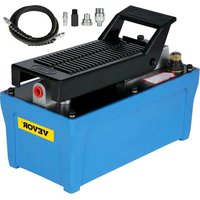
AIR POWERED HYDRAULIC FOOT PUMP USER MANUAL
MODEL: TL-A5102
TL-A5121
We continue to be committed to provide you tools with competitive price. "Save Half", "Half Price" or any other similar expressions used by us only represents an estimate of savings you might benefit from buying certain tools with us compared to the major top brands and does not necessarily mean to cover all categories of tools offered by us. You are kindly reminded to verify carefully when you are placing an order with us if you are actually saving half in comparison with the top major brands.
VEVOR®
TOUGH TOOLS, HALF PRICE
AIR POWERED HYDRAULIC
FOOT PUMP
MODEL: TL-A5102、TL-A5121

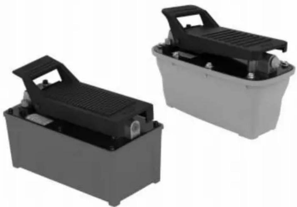
natural_image
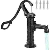
Two black plastic electrical equipment boxes with handles and mounting feet, shown from different angles (no text or symbols visible)Repair parts sheets for hydraulic hand pumps are available from your nearest authorized service center or sales office.
NEED HELP? CONTACT US!
Have product questions? Need technical support? Please feel free to contact us:
Technical support and E-warranty certificate
Www.vevor. com /support
This is the original instruction . please read all manual instructions carefully before operating. VEVOR reserves a clear interpretation of user manual . The appearance of the product shall be subject to product you received . please forgive us that we won't inform you there are any technology or software updates on our product.
Before the operation, please read the operation manual carefully to know the equipment and the correct method of use. please keep it for future reference.
SAFETY PRECAUTIONS
NOTE
PLEASE READ AND FOLLOW THIS INSTRUCTION BEFORE YOU USE THE AIR HYDRAULIC PUMP.
carefully inspect all components for shipping damage if shipping damage is found. please notify the carrier at once. The carrier is responsible for any damage resulting from shipment.
1. SAFETY

To avoid personal injury or property damage, please fallow
safety precautions cannot be responsible for injury or damage resulting from unsafe and incorrect product use or system operation, or lack of maintenance.
DANGER is used when your action or lack of action may cause serious injury or even death.
WARNING indicates a potential danger that requires correct action to avoid personal injury.
IMPORTANT indicates correct action to prevent damage or equipment failure

DANGER
●The hydraulic equipment operator must be a qualified operator familiar with the correct training and work experience in hydraulic equipment. A lack of knowledge in any of these areas can lead to equipment damage
personal injury.
- To avoid personal injury, please do not modify or weld hydraulic equipment without approval.
- please never lift more than the rated capacity of the cylinder.
overloading causes equipment failure and serious personal injury.
- The cylinder is a load-lifting device, not a load-holding device. After the load has been raised or lowered, it must always be held mechanically. Never work under a load supported by a hydraulic unit.
- keep hands and feet away from the cylinder and workplace during operation to avoid personal injury.
- Do not put unbalanced or off-center loads on cylinders. The incorrect load can result in equipment failure and serious personal injury.

WARNING
- wear safety glasses, helmets, and other necessary personal protective equipment when operating hydraulic equipment.
- cylinder used to lift the load must have a solid footing for correct sup please select steel or woodblocks that are capable of supporting the load
- install pressure gauges in the system to monitor the operating
pressure. The gauge must have the same pressure rating as the pump cylinder. The wrong gauges may result in personal injury.
- The system operating pressure must be lower than the lowest rated pressure in the system.
- (carefully inspect the cylinder and couplers before using the cylinder. Never connect the cylinder with damaged couplers or damaged port threads. The damaged coupler or damaged port threads may cause equipment failure and possible personal injury.
- Install the coupler in a clean environment; prevent dirt or other debris from entering the cylinder body or tube. Dirt or other debris will damage cylinder and result in equipment failure and possible personal injury. Before removing or tightening the hose or coupler, release hydraulic pressure in the system.
- Never handle pressurized hoses; escaping oil under high pressure can penetrate the skin, causing serious injury. seek medical aid immediately injured.
- please use or other approved hydraulic oil
- For hydraulic technical help or repair service. please contact the authorized service center in your area. Has no obligations under any warranty with respect to products that have been repaired by unauthorized personnel, modified, or damaged through misuse, abuse, accident, neglect, or mishandling.
IMPORTANT
- keep the air hydraulic pump clean all the time.
- when the Air hydraulic pump is not in use, release the valve, remove the hose, and use a rubber cap to recover the port.
- Do not drop objects on the hose.
- Do not lift and carry hydraulic equipment by the hoses or couplers; use the handle or other means.
- use hydraulic equipment at normal operating temperatures. Do not use equipment in temperatures of 65^(150^) or higher. overheating will
soften seals and weakens hose materials, resulting in oil leaking or other equipment failures.
Air Hydraulic pump supplies hydraulic fluid pressure to selected tools. It consists of an in-line air and a hydraulic cylinder.
SPECIFICATIONS
| Model | TL-A5121 | TL-A5102 | |
| Pressure Rating(psi) | 10000 | 10000 | |
| Useable Oi Capacity(cu.in) | 98 | 98 | |
| Available Capacity | 2.3L | 1.6L | |
| Air/Hydraulic Ratio | 100:1 | 100:1 | |
| Flow(@100Psi) | 0.8L/min | 0.8L/min | |
| Flow(@10,000Psi) | 0.16L/min | 0.16L/min | |
| Input Air pressure(psi) | 110-145 | 110-145 | |
| Input Port Threads(NPT) | 1/4"-18 | 1/4"-18 | |
| Output Port Threads(NPT) | 3/8"-18 | 3/8"-18 | |
| Operation Manner | Foot Pedal | Foot Pedal | |
| Oil Delivery (cu.in/min) | No Load | 49.5 | 49.5 |
| Load | 7.6 | 7.6 | |
| Oiltank Material | Plastic | Aluminum | |
standard accessories
| MODEL | SSX | SKU | DESCRIPTION | QTY |
| TL-A5102 | SS1 | BTQBTYYJTBLSK0001 | Hydraulic pump | 1 |
| 2M Oil Hose | 1 | |||
| Cross-over Sub | 1 | |||
| Hermaphrodite connector | 1 | |||
| 1 M long air gun | 1 |
| MODEL | SSX | SKU | DESCRIPTION | QTY |
| TL-A512' | SS2 | QDYYBHSBD2.3L9FR9 | Hydraulic pump | 1 |
| 2M Oil Hose | 1 | |||
| Male connector | 1 | |||
| 1 M long air gun | 1 | |||
| TL-A5101 | SS3 | BTQJTBCS000000001 | Hydraulic pump | 1 |
| 2M Oil Hose | 1 | |||
| Cross-over Sub | 1 | |||
| Hermaphrodite connector | 1 | |||
| 1 M long air gun | 1 |
| MODEL | SSX | SKU | DESCRIPTION | QTY |
| TL-A510 | SS4 | QDJTYYBJPQTZ00001 | Hydraulic pump | 1 |
| 1.25M Oil Hose | 1 | |||
| Hermaphrodite connector | 1 | |||
| 1 M long air gun | 1 |
| MODEL | SSX | SKU | DESCRIPTION | QTY |
| TL-A510 | SS5 | CSMJTELECTRIC8CJI | Hydraulic pump | 1 |
| MODEL | SSX | SKU | DESCRIPTION | QTY |
| TL-A510 | SS6 | HSMJTELECTRIC8F6H | Hydraulic pump | 1 |
| 2M Oil Hose | 1 |
| MODEL | SSX | SKU | DESCRIPTION | QTY |
| TL-A5101 | SS7 | BTQJTB2510A000001\ | Hydraulic pump | 1 |
| 2M Oil Hose | 1 | |||
| Hermaphrodite connector | 1 |
| MODEL | SSX | SKU | DESCRIPTION | QTY |
| TL-A5102 | SS8 | CGKQB18MJTHSFZYLVO | Hydraulic pump | 1 |
| 2M Oil Hose | 1 | |||
| Hermaphrodite connector | 1 | |||
| Adapter | 1 | |||
| Teflon tape | 1 |
| MODEL | SSX | SKU | DESCRIPTION | QTY |
| TL-A512 | SS9 | CGKQBWDZYHS1405V0 | Hydraulic pump(Equipped with a 3m line len controller) | 1 |
| Teflon tape | 1 |
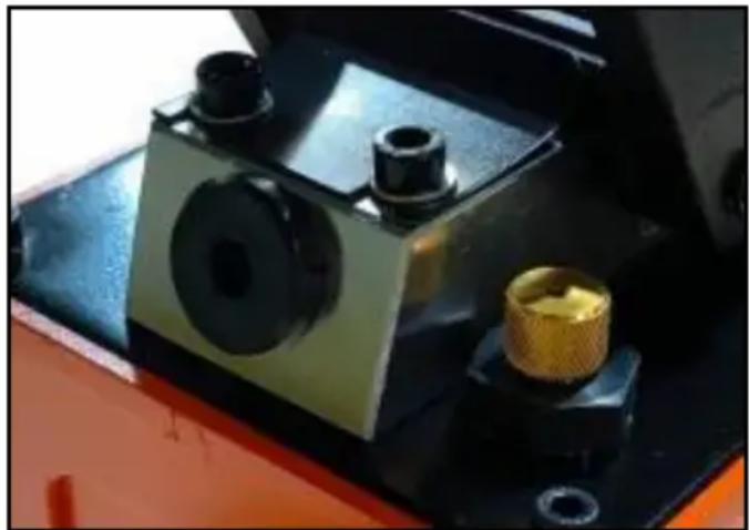
To prevent oil leaks during shipment, a metal knob is installed and tightened to ensure the best sealing function. Loosen it counter clock wise before use.
Note: Always secure threaded port connections with a non-hardening pipe thread compound. Tighten securely to prevent accidental removal of components while in use. Take care not to introduce compounds into port orifices. Familiarize yourself with the specifications and illustrations in this operator's manual. know your pump, its limitations, and how it operates before attempting to use it.
natural_image
Close-up of a mechanical device with black and gold components, no visible text or symbolsRefer to the specification chart above for details of oil port thread size, usable oil capacity, and more.
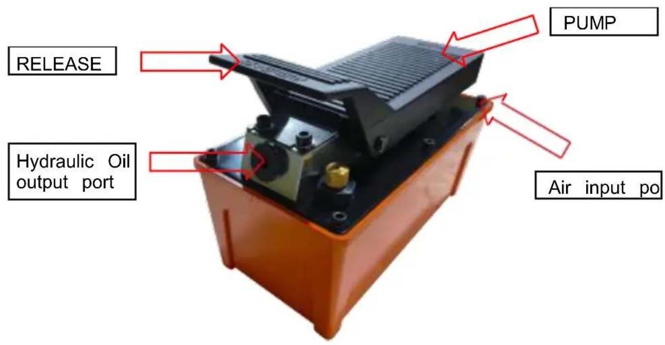
OPERATION
The operation of the unit is as follows:
-
connect the hose of the Air Hydraulic pump to the hydraulic coupling on the selected tool.
-
connect the air supply line to the Air Hydraulic pump. The air supply is
5- 10 CFM at 100 PSI to obtain proper operating characteristics. In addition the airline should be equipped with an air line filter.
Foot pedal operate pumps:
a. Depress the "pump" end of the pedal will pump hydraulic oil into
the system.
b. stop depressing the "pump" or "Release" end will stop and hold the pressure.
C. Depress the "Release" end of the pedal will release the pressure in the system.
MAINTENANCE
1. Inspect the connections
please Inspect hoses and connections and tighten connections as needed. use a non-hardening pipe thread compound when servicing connections.
2. Adding Hydraulic Fluid
- Depressurize and disconnect the hydraulic hose from the application.
●with the pump in its upright, horizontal position, remove the oil filler plug located on the top plate of the reservoir. - use a small funnel to fill reservoir to within 3/4" (19mm) of the opening.
- wipe up any spilled fluid and reinstall the oil filler plug.
Note: use only or other approved hydraulic oil . Never use brake fluid ,
transmission fluid, turbine oil, motor oil, alcohol, glycerin, etc. use of other than good quality hydraulic oil will void the warranty and damage the pump and application.
3. changing Hydraulic Fluid
- For best results, change the fluid once a year.
- Repeat step 2 above, and then pour the used fluid into a sealable container. · Dispose of the fluid in accordance with local regulations.
- Fill with good-quality hydraulic oil as recommended above. Reinstall the vented oil filler plug.
4. Lubrication
use a light machine oil to lubricate pivot points, hinges, etc.
5. storage
- Depressurize and disconnect hydraulic hoses from the application.
- clean the pump and hose, and couplers.
- store in a clean, dry environment; avoid temperature extremes.
TROUBLE SHOOTING

IMPORTANT:
Hand pumps should be repaired only by qualified or Authorized service centers. Repairing the hand without special tools and knowledge may result in injury. Always release pressure and disconnect before making repairs
| symptom | possible causes | corrective Action |
| Application will not extend, move or respond to pressurized fluid | · overload condition· Release valve not closed | · Remedy overload condition· Ensure the release valve closed |
| Application responds to pressurized fluid, but the system does not maintain pressure | · overload condition· Release valve not closed· Hydraulic unit Malfunction | · Remedy overload condition· Ensure the release valve closed |
| Application will not return fluid to pump (i.e. cylinder will not retract) | · Malfunctioning coupler, damaged application· Reservoir overfilled | · secureload by other means. open the release valve, depressurize the pump and hose, remove the coupler and/or application, then renew o replace· secureload by other means. open the release valve, depressurize the pump and hose, remove the coupler and/or application, then drain the fluid to a proper level |
| Application will not fully extend (cylinder or spreader) | · Fluid level low | · Follow the symptom 3 procedure for securing the load depressurizing the pump, removing the application, then ensuring the proper fluid level |
| poor performance | · Air trapped in the system | Ensure the proper fluid level Ensure the vented oil filler plug lets pressurized reservoir air escape(see BEFORE USE) |
VEVOR®
TOUGH TOOLS, HALF PRICE
Technical Support and E-Warranty Certificate www.vevor.com/support
VEVOR®
TOUGH TOOLS, HALF PRICE
Support technique et E-Mandat y Certificat www.vevor.com/support
AIR ALIMENTÉ HYDRAULIQUE PIED POMPE UTILISATEUR MANUEL
MODÈLE : TL- A5102 TL- A5121
natural_image
Two black and gray plastic electrical equipment blocks with visible internal components (no text or symbols)accessoires standards
natural_image
Close-up of a mechanical device with black components and a gold-colored fitting, no visible text or symbols.1. Inspector le relations
natural_image
Two black and gray plastic electrical equipment blocks with visible internal components (no text or symbols)natural_image
Close-up of a mechanical device with black components and a gold-colored fitting, no visible text or symbols.natural_image
Two black and gray plastic electrical equipment blocks with visible internal components (no text or symbols)natural_image
Close-up of a mechanical device with black components and a gold-colored fitting, no visible text or symbols.MODELO: TL- A5102 TL- A5121
natural_image
Two black and gray electronic devices with visible ports and mounting brackets (no text or symbols)natural_image
Close-up of a mechanical device with black components and a gold-colored fitting, no visible text or symbols.MODELE: TL-A5102, TL-A5121