RT015 - Milling machine Vevor - Free user manual and instructions
Find the device manual for free RT015 Vevor in PDF.

| Product Type | Table Router (Router Table) |
| Brand | Vevor |
| Model | RT015 |
| Table Dimensions | 800 x 606 x 36 mm (32 x 24 x 1-3/8 in) |
| Miter Slot (Aluminum) | 800 mm (32 in) |
| Table Insert | 306 x 229 mm (9 x 12 in) |
| Fence | 460 x 150 mm (18 x 6 in) |
| Fence Dust Port | 63 / 77.3 / 68.2 mm (2-1/2 x 3 in) |
| Fence Rule Label | 456 mm (18 in) |
| Stand Height | 1025 mm |
| Stand Material | Steel with Rubber Feet |
| Weight | Approx 25 kg (estimated) |
| Power Supply | To be connected to a suitable power source (not specified) |
| Main Functions | Routing, profiling, grooving with fence and miter guide |
| Safety | Safety glasses, respirator, hearing protection required; do not wear loose clothing |
| Maintenance and Cleaning | Keep blades sharp and clean; unplug before any adjustment or tool change |
| Spare Parts and Repairability | Complete parts list provided; assembly by customer; technical support at www.vevor.com/support |
| General Information | User manual and instructions available in multiple languages; electronic warranty certificate |
Frequently Asked Questions - RT015 Vevor
User questions about RT015 Vevor
0 question about this device. Answer the ones you know or ask your own.
Ask a new question about this device
Download the instructions for your Milling machine in PDF format for free! Find your manual RT015 - Vevor and take your electronic device back in hand. On this page are published all the documents necessary for the use of your device. RT015 by Vevor.
USER MANUAL RT015 Vevor
Affordable. Reliable. Home Improvement.
RUTER TABLE
MODEL: RT015
Technical Support and E-Warranty Certificate www.vevor.com/support
VEVOR
Affordable. Reliable. Home Improvement.
RUTER TABLE
MODEL: RT015

natural_image
3D rendering of a simple metal workbench with a circular cutter and flat top (no text or symbols visible)This is the original instruction, please read all manual instructions carefully before operating. VEVOR reserves a clear interpretation of our user manual. The appearance of the product shall be subject to product you received. Please forgive us that we won't inform you ag if there are any technology or software updates on our product.
General Safety Instructions
Extreme caution should be used when operating all power tools. Know your power tool, be familiar with its operation, read through the owner's manual and practice safe usage procedure at all times.
- CONNECT your machine ONLY to the matched and specific power source.
- ALWAYS wear safety glasses respirators, hearing protection and safety shoes, when operating your machine.
- DO NOT wear loose clothing or jewelry when operating your machine.
- A safe environment is important. Keep the area free of dust, dirt and other debris in the immediate vicinity of your machine.
- DISCONNECT the power source when changing drill bits, hollow chisels, router bits, shaper heads, blades, knives or making other adjustments or repairs.
- ALWAYS keep all safety guards in place and ensure their proper function
- NEVER reach over the table when the tool is in operation. It is dangerous.
- ALWAYS keep blades, knives and bits sharpened and properly aligned.
- NEVER leave a tool unattended while it is in operation.
- BE ALERT! DO NOT use prescription or other drugs that may affect your ability or judgment to safely use your machine.
- ALWAYS use push sticks and feather boards to safely feed your work through the machine.
- ALWAYS make sure that any tools used for adjustments are removed before operating the machine.
- Always keep the bystanders safely away while the machine is in operation.
Router Table with Fence & Stand Specific Safety Instructions
Like all power tools and machinery, proper safety and attention must be adhered to. There is danger associated with using any tool or machine so pay careful attention each and every time you use your tool. If you are not familiar with the operations router table, you should obtain the advice and/or instructions from a qualified professional.
- MAKE SURE the router has been installed securely before staring the machine, for safe operation method.
- NEVER perform any "Free Hand" operation. Do not use your hands to support or guide the work piece. Always use toggle clamp to secure t work piece for cutting.
- DO NOT wear jewelry or loose clothing while operating this machine.
- SAFETY GLASSES & RESPIRATOR is highly recommended when working with this machine. Some saw dust can be harmful to your lungs; please take caution when using this machine.
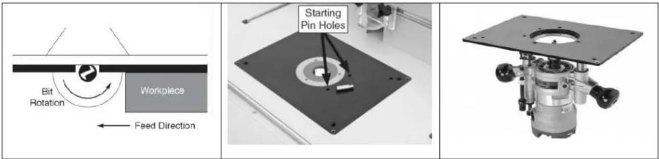
- ALWAYS feed the work piece to the router bit against the rotation direction
-
INSPECT your work pieces. Make sure that they are free of nails, staples, tacks, knots and other object that may be harmful to your router I
-
DO NOT jam or try and over push work piece into the machine during operation. This may cause damage the machine. Feed the work piece a firm grasp, slowly and easily and hold the work piece against the fer
- MAKE SURE the spindle rotates in correct direction.
- DO NOT let anyone stand in front of the machine while operation.
- TECHNICAL DIFFICULTIES. Any problems you may run into should carefully looked at with the power and the machine unplugged from the power source.
- NEVER draw the work piece back during the cutting operation. Stop the router bit before drawing back the work piece.
- ALWAYS keep bits sharpened and clean.
IMPORTANT: The safety instructions given above can not be complete because the environment in every shop is different. Always consider safety first as it applies to your individual working conditions.
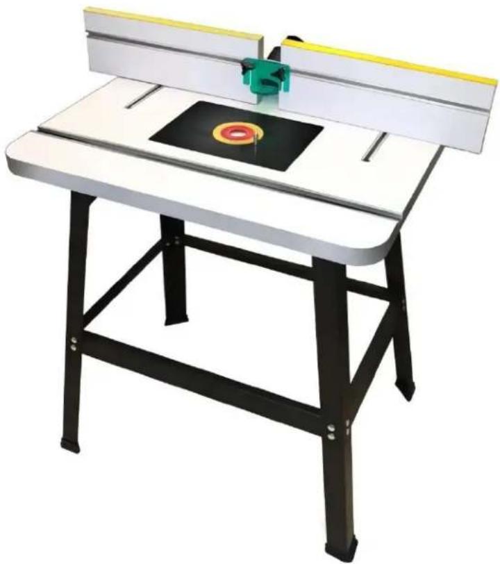
ROUTER TABLE FEATURES
TABLE TOP
Size: 800*606*36mm
Aluminum Miter Track: 800mm
Table Insert: 306*229mm
FENCE
Size: 460*150mm
Dust Port: 63/77.3/68.2mm
Gaurd: Fluorescent Plastic Plate
Aluminum Miter Track: 460mm
Ruler Label: 456mm
STAND
Made of: Steel
Height: 1025mm
Includes: 4 non-marring Rubber Feet
PHYSICAL FEATURES

ASSEMBLY & INSTALLATION
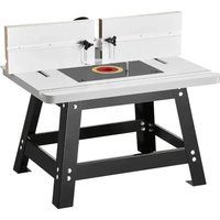
Before assembling the stand, please take Now, mount the two other longer and the a look at the list below. Your stand cometwo short angle braces to the legs with the with the following parts and mounting help of the nuts and bolts, (Finger hardware. Tighten). See Figure-2
- Short Angle Brace: 2-pcs
- Shorter Angle Brace: 2-pcs
- Long Angle Brace: 2-pcs
- Longer Angle Brace: 2-pcs
• Round Head Bolt M8x12: 32-pcs
• Hex Nut M8: 32-pcs - Flat Washer8: 32-pcs
- Hex Bolt M6x16: 4-pcs
- Flat Washer: 4-pcs
- Rubber Feet: 4-pcs
Stand Assembly
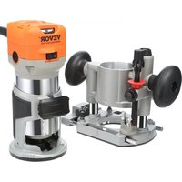
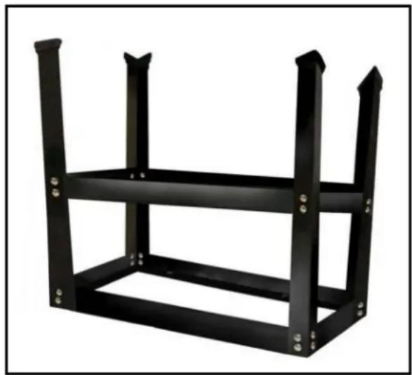
Take the two short and the two longer angle braces out of the box and put it on the floor. Now take the four legs upside down, and attach them to the four braces using 1/4" x 1/2" nuts and bolts. (Finger tighten) See Figure-1.
natural_image
Black metal shelving unit with three vertical supports and mounting holes (no text or symbols)Figure-1 Attaching legs to the braces
natural_image
Black metal frame structure with four vertical supports and mounting holes (no text or symbols)Figure-2 Attaching the middle braces to the legs
Now, turn the stand upright and adjust the legs so that they are evenly positioned, tighten all the screws well.
Installing the Router Table on the Stand
Take the router table and put it upside down on the floor or bench. The router table and the upper braces of the stand feature 4 holes to mount the router table to the stand. Position the stand inverted, on the router table so that the holes are aligned and then mount it with the help of washers and bolts provided, (Finger Tighten). See Figure-3
ASSEMBLY & INSTALLATION
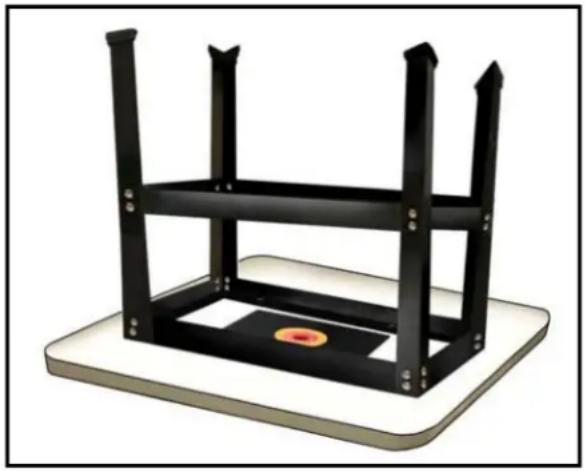
natural_image
3D rendering of a black metal frame structure with three vertical supports and a circular base (no text or symbols)Figure-3 Mounting the stand to the route table
Take the 4 rubber feet out of the pack and attach one on each leg. Now, turn stand up right and your router table is installed on the stand.
Mounting the Router Base Plate in Your Router Table
When mounting a large router, the handles should fit in the same direction the long opening. Your current router base plate will function as the drilling jig. However, you should determine the optimum router positioning before the base plate. Make sure to take into account the depth adjustment knobs, depth lock levers/knobs and the location of your switch. Place your router in pro inverted position under the table. Then mark with tape on the front edge of the router's bed plate to verify the position.
Then, remove the screws from the base plate. Locate the top/front of your base plate by observing the position of the
starting pin holes. The holes will be to the right of the opening. Again mark with the tape the front and center on the plate to serve as a reminder.
Center the router base plate on the nearest concentric ridge. Then position the mounting holes along the radial lines. Keep the base plate in place with tape. (3 to 4 pieces arranged around the ring should be adequate).
Next, clamp the 2 plates together using C-clamps or wood.
Note: Spring clamps will not provide enough clamping force and could allow the parts to move out of place.
Drill through the new base using a drill bit that matches the size of the holes in your router's base plate.
Note: If available, perform this operation on a drill press to keep the holes perpendicular.
Important: A piece of wood should be clamped to the front of the router plate whole drilling to avoid splintering of the plate.
After removing the clamps, countersink holes similar to the router's own base plate. For best result, we recommend a single flute countersink at a slow speed and a drill press if available.
Finally, mount the base plate to the router. If the screws that came with your router are not long enough, longer screws can be purchased at a hardware store or home center in your area.
If you are unsure about the installation process, p check the installation video.
Stand Parts Break-Down & Parts List
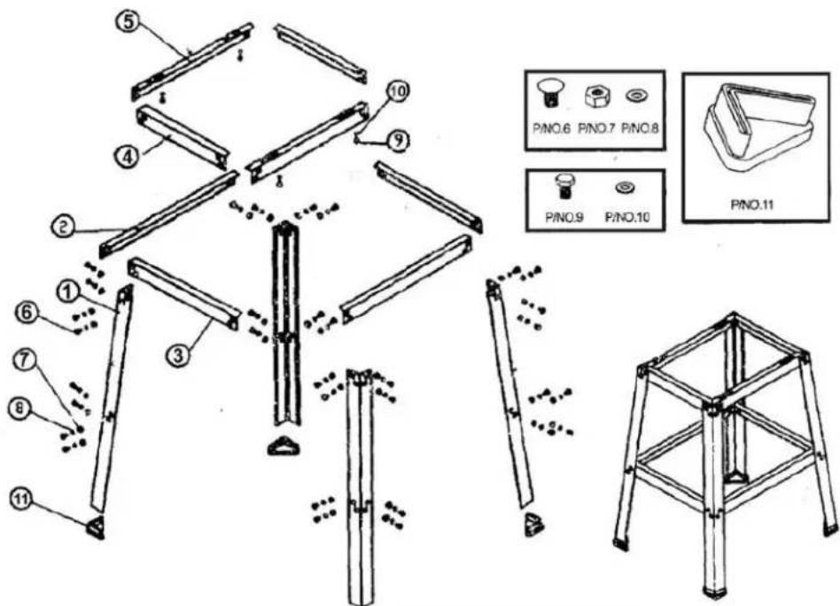
| NO | DESCRIPTION | QTY |
| 1 | Longer Angle Brace | 4 |
| 2 | Short Angle Brace | 2 |
| 3 | Short Angle Brace | 2 |
| 4 | Short Angle Brace | 2 |
| 5 | Longer Angle Brace | 2 |
| 6 | Round Head Bolt M8 x 12 | 32 |
| 7 | Hex Nut M8 | 32 |
| 8 | Flat Washer8 | 32 |
| 9 | Hex Bolt M6 x 16 | 4 |
| 10 | Flat Washer6 | 4 |
| 11 | Rubber Feet | 4 |
Router Table Parts Break-Down & Parts List
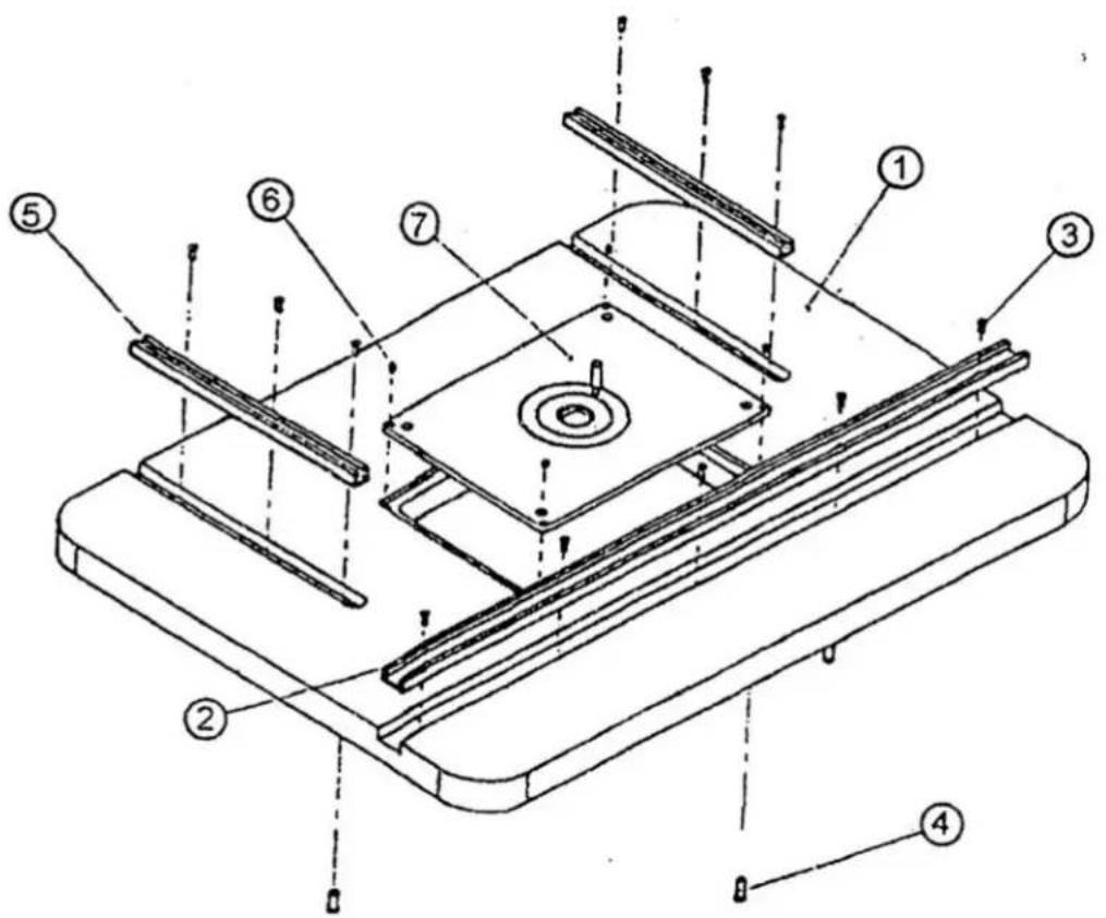
| NO | QTY | PART | DESCRIPTION |
| 1 | 1 | Table Top | 32" x 24" x 1-3/8" |
| 2 | 1 | Aluminum Miter Track | Length 32" |
| 3 | 11 | Flat Head Tapping Screw | 4" x 1/2" |
| 4 | 4 | Nut | M 1/4" x 1/2" |
| 5 | 2 | Aluminum T-Track | Length 11-3/4" |
| 6 | 4 | Hex Socket Set Screw | 6 x 6 |
| 7 | 1 | Insert + Guide Pin | 9" x 12" |
Fence Parts Break-Down & Parts List
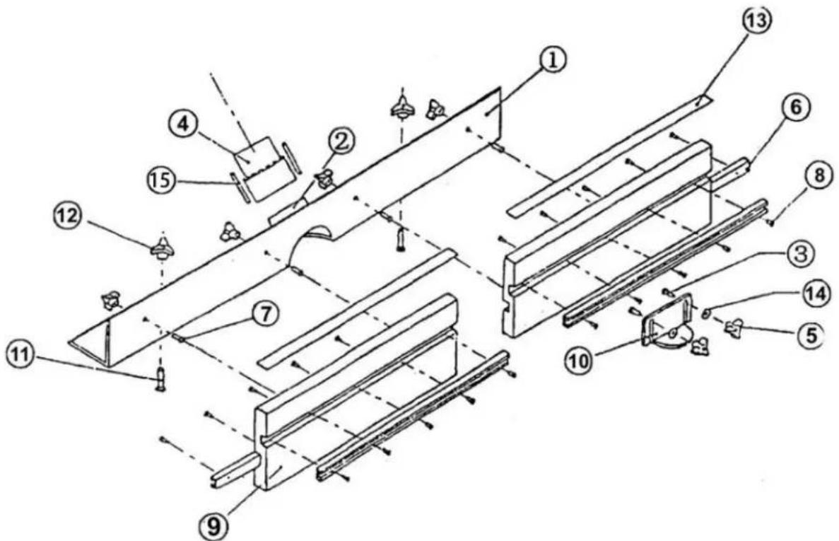
| NO | QTY | PART | DESCRIPTION |
| 1 | 1 | L-Aluminum | 4” x 4” x 33” |
| 2 | 1 | Adapter | 2-1/2” x 2” |
| 3 | 2 | Pan-Head Machine Screw | 1/4” x 1” |
| 4 | 1 | Dust Port | 2-1/2” x 3” |
| 5 | 2 | Triangle Knob | 1/4" |
| 6 | 4 | Aluminum-Miter Track | Length 18” |
| 7 | 2 | Hex Bolt | 5/6” x 1” |
| 8 | 20 | Flat Head Tapping Screw | 4# x 1/2" |
| 9 | 2 | Fence | 18” x 6” x 1” |
| 10 | 1 | Bit Cover | Fluorescent Plastic Plate |
| 11 | 4 | Hex Bolt | 5/16” x 1” |
| 12 | 6 | Knob | 5/16” |
| 13 | 2 | Ruler Label | Length 18” |
| 14 | 2 | Flat Washer | 1/4" |
| 15 | 2 | Pan-Head Machine Screw | 3/16”x 2-1/4” |
Customers need to assemble it by below parts :
| RT015: | Part name | Quantity |
| 1. | Round Head Bolt M8 x 12 | 32 |
| 2. | Hex Nut M8 | 32 |
| 3. | Flat Washer8 | 32 |
| 4. | Hex Bolt M6 x 16 | 4 |
| 5. | Flat Washer6 | 4 |
| 6. | Knob 5/16”+Hex Bolt 5/16” x 1”+Flat Washer 5/16 | 6 |
| 7. | Knob 1/4”+Hex Bolt 1/4” x 1”+Flat Washer 1/4” | 2 |
| 8. | Pan-Head Machine Screw 3/16“x 2-1/4” | 2 |
| 9. | Ruler Label Length 18” | 2 |
| 10. | Bit Cover Fluorescent Plastic Plate | 1 |
| 11. | Dust Port 2-1/2” x 3” | 1 |
| 12. | Adapter 2-1/2” x 2” | 1 |
| 13. | Fence 18” x 6” x 1” | 2 |
| 14. | Table Top 32” x 24” x 1-3/8” | 1 |
| 15. | Insert + Guide Pin 9” x 12” | 1 |
| 16. | Aluminum Miter Track Length 32” | 1 |
| 17. | Longer Angle Brace | 2 |
| 18. | Short Angle Brace | 2 |
| 19. | Short Angle Brace | 2 |
| 20. | Short Angle Brace | 2 |
| 21. | Longer Angle Brace | 4 |
| 22. | M3 hex wrench | 1 |
| 23. | Rubber Feet | 4 |
| 24. | Position axis | 1 |
| 25. | M4 * 16 countersunk cross bolt * 4 (with fixed rout) | 4 |

Technical Support and E-Warranty Certificate
www.vevor.com/support
VEVOR
Affordable. Reliable. Home Improvement.
RUTER TABELA
MODEL: RT015
Affordable. Reliable. Home Improvement.
RUTER TABLE
MODEL: RT015

natural_image
3D rendering of a simple metal workbench with a circular cutter and flat top (no text or symbols visible)Aluminium Mitra Tor: 800mm
natural_image
Black metal shelving unit with three vertical supports and mounting holes (no text or symbols visible)Podstawka Montaż
natural_image
3D rendering of a black metal frame structure with three vertical supports and a circular base (no text or symbols)www.vevor.com/support
VEVOR
Affordable. Reliable. Home Improvement.
RUTER TISCH
MODELL: RT015
Affordable. Reliable. Home Improvement.
RUTER TABLE
MODELL: RT015

natural_image
3D rendering of a simple metal workbench with a circular cutter and flat blade (no text or symbols visible)natural_image
Black metal shelving unit with three vertical supports and mounting holes (no text or symbols visible)Stand Montage
natural_image
Metal frame structure with four vertical supports and mounting holes (no text or symbols visible)natural_image
3D rendering of a black metal frame structure with a circular base and mounting base (no text or symbols)| NEI | MEN | TEIL | BESCHREIBUNG |
| 1 | 1 | LA -Leuchtstoff | 4” x 4” x 33 Zoll |
| 2 | 1 | Adapter | 2-1/2” x 2” |
| 3 | 2 | Pan-Head-Maschine | 1/4 Zoll x 1 ” |
| 4 | 1 | Staub Hafen | 2-1/2” x 3” |
| 5 | 2 | Dreieck Knopf | 1 /4 Zoll |
| 6 | 4 | Aluminium- | Länge 18 Zoll |
| 7 | 2 | Verhexen Bolzen | 5/6 " x 1 " |
| 8 | 20 | Flachkopfgewindebohren | 4# x 1/2 Zoll |
| 9 | 2 | Zaun | 18” x 6” x 1” |
| 10 | 1 | Bisschen Abdeckung | Fluoreszierender |
| 11 | 4 | Verhexen Bolzen | 5/16” x 1” |
| 12 | 6 | K nob | 5/1 6” |
| 13 | 2 | Herrscher Etikett | Länge 18 Zoll |
| 14 | 2 | Unterlegscheibe | 1 /4 Zoll |
| 15 | 2 | Linsenkopf- | 3/16“ x 2-1/4” |
www.vevor.com/support
VEVOR
Affordable. Reliable. Home Improvement.
RUTER TABLEAU
MODÈLE : RT015
www.vevor.com/support
VEVOR
Affordable. Reliable. Home Improvement.
RUTER TABLE
MODÈLE: RT015

natural_image
3D rendering of a simple metal workbench with a circular cutter and flat top (no text or symbols visible)natural_image
Black metal frame structure with four vertical supports and mounting holes (no text or symbols)Rester Assemblée
natural_image
Metal frame structure with four vertical supports and mounting holes, labeled as Figure-1 (no text on frame itself)natural_image
3D rendering of a black metal frame structure with a circular base and mounting base (no text or symbols)Affordable. Reliable. Home Improvement.
RUTER TAFEL
MODEL: RT015
www.vevor.com/support
VEVOR
Affordable. Reliable. Home Improvement.
RUTER TABLE
MODEL: RT015
natural_image
3D rendering of a simple metal workbench with a circular cutter and flat top (no text or symbols visible)natural_image
Black metal shelving unit with three vertical supports and mounting holes (no text or symbols visible)Stellage Montage
natural_image
Black metal bracket with four vertical supports and mounting holes (no text or symbols)natural_image
3D rendering of a black metal frame structure with a circular base and mounting base (no text or symbols)| NEE | BESCHRIJVING | Hoeveelheid |
| 1 | Langere hoek Beugel | 4 |
| 2 | Korte hoek Beugel | 2 |
| 3 | Korte hoek Beugel | 2 |
| 4 | Korte hoek Beugel | 2 |
| 5 | Langere hoek Beugel | 2 |
| 6 | Ronde kopbout M8 x 12 | 32 |
| 7 | Zeskantmoer M8 | 32 |
| 8 | Vlakke ring8 | 32 |
| 9 | Zeskantbout M6 x 16 | 4 |
| 10 | Vlakke ring6 | 4 |
| 11 | Rubberen voetjes | 4 |
| NEE | Hoeve | DEEL | BESCHRIJVING |
| 1 | 1 | Tafel Bovenkant | 32” x 24” x 1-3/8” |
| 2 | 1 | Aluminium verstekzaag | Lengte 32” |
| 3 | 11 | Platte kop tikken Schroe | 4” x 1/2" |
| 4 | 4 | Moer | M 1/4” x 1/2" |
| 5 | 2 | Aluminium T-spoor | Lengte 11-3/4” |
| 6 | 4 | Zeskant copsleutelset | 6 stuks 6 |
| 7 | 1 | Invoegen + Gids Pin | 9” x 12” |
| NEE | Hoeve | DEEL | BESCHRIJVING |
| 1 | 1 | LA- luminium | 4" x 4" x 33" |
| 2 | 1 | Ada -pter | 2-1/2" x 2" |
| 3 | 2 | Pan-kopmachine Schroef | 1/4 " x 1/4" 1 " |
| 4 | 1 | Stof Haven | 2-1/2" x 3" |
| 5 | 2 | Driehoek Knop | 1 /4" |
| 6 | 4 | Aluminium- verstekrail | Lengte 18" |
| 7 | 2 | Zeshoek Bout | 5/6 " x 1,5 cm 1 " |
| 8 | 20 | Platte kop tikken Schroe | 4#x 1/2" |
| 9 | 2 | Schutting | 18" x 6" x 1" |
| 10 | 1 | Beetje Omslag | Fluorescerend plastic |
| 11 | 4 | Zeshoek Bout | 5/16" x 1" |
| 12 | 6 | K -nob | 5/1 6" |
| 13 | 2 | Liniaal Label | Lengte 18" |
| 14 | 2 | Vlakke ring | 1 /4" |
| 15 | 2 | Pankopmachineschroef | 3/16" x 2-1/4" |
Affordable. Reliable. Home Improvement.
RUTER TABELL
MODELL: RT015
www.vevor.com/support
VEVOR
Affordable. Reliable. Home Improvement.
RUTER TABLE
MODELL: RT015

natural_image
3D rendering of a simple metal workbench with a circular cutter and flat top (no text or symbols visible)natural_image
Black metal shelving unit with three vertical supports and mounting holes (no text or symbols)natural_image
Black metal frame structure with four vertical supports and mounting holes (no text or symbols)natural_image
3D rendering of a black metal frame structure with a circular base and mounting base (no text or symbols)| ING | ANT | P ART | BESKRIVNING |
| 1 | 1 | LA aluminium | 4" x 4" x 33" |
| 2 | 1 | Ada pter | 2-1/2" x 2" |
| 3 | 2 | Pan-Head maskin Skruva | 1/4 " x 1 " |
| 4 | 1 | Damm Hamn | 2-1/2" x 3" |
| 5 | 2 | Triangel Knopp | 1/4 " |
| 6 | 4 | Aluminium- geringsbana | Längd 18" |
| 7 | 2 | Hex Bult | 5/6 " x 1 " |
| 8 | 20 | Knackning med platt | 4# x 1/2" |
| 9 | 2 | Fen ce | 18" x 6" x 1" |
| 10 | 1 | Bit Täcka | Fluorescerande plast |
| 11 | 4 | Hex Bult | 5/16" x 1" |
| 12 | 6 | K nob | 5/1 6" |
| 13 | 2 | Linjal Märka | Längd 18" |
| 14 | 2 | Platt bricka | 1/4 " |
| 15 | 2 | Pan-Head maskinskruv | 3/16"x 2-1/4" |
Affordable. Reliable. Home Improvement.
RUTER MESA
MODELO: RT015
Affordable. Reliable. Home Improvement.
RUTER TABLE
MODELO: RT015

natural_image
3D rendering of a simple metal workbench with a circular cutter and flat top (no text or symbols visible)natural_image
Black metal frame structure with four vertical supports and mounting holes (no text or symbols)Pararse Asamblea
natural_image
Black metal frame structure with four vertical supports and mounting holes (no text or symbols)natural_image
3D rendering of a black metal frame structure with a circular base and mounting base (no text or symbols)| NO | CAN | PARTE | DESCRIPCIÓN |
| 1 | 1 | LA luminum | 4" x 4" x 33" |
| 2 | 1 | Adaptador | 2-1/2" x 2" |
| 3 | 2 | Máquina de cabezal | 1/4 "x 1 " |
| 4 | 1 | Polvo Puerto | 2-1/2" x 3" |
| 5 | 2 | Triángulo Perilla | 1/4 " |
| 6 | 4 | Riel de inglete de alumí | Longitud 18" |
| 7 | 2 | Maleficio Tornillo | 5/6 "x 1 " |
| 8 | 20 | Roscado de cabeza plan | 4# x 1/2" |
| 9 | 2 | Cerca | 18" x 6" x 1" |
| 10 | 1 | Poco Cubrir | Plástico fluorescente |
| 11 | 4 | Maleficio Tornillo | 5/16" x 1" |
| 12 | 6 | Perilla | 5/1 6" |
| 13 | 2 | Gobernante Etiqueta | Longitud 18" |
| 14 | 2 | Arandela plana | 1/4 " |
| 15 | 2 | Tornillo de máquina de | 3/16" x 2-1/4" |
Affordable. Reliable. Home Improvement.
ROUTER TAVOLO
MODELLO: RT015
Affordable. Reliable. Home Improvement.
RUTER TABLE
MODELLO: RT015

natural_image
3D rendering of a simple metal workbench with a circular cutter and flat top (no text or symbols visible)natural_image
Black metal shelving unit with three vertical supports and two horizontal shelves (no text or symbols visible)natural_image
Black metal frame structure with four vertical supports and mounting holes (no text or symbols)Figura 2 Allegando IL mezzo bretelle al gambe