RT017 - Milling machine Vevor - Free user manual and instructions
Find the device manual for free RT017 Vevor in PDF.

| Product Type | Router Table with Stand |
| Brand | Vevor |
| Model | RT017 |
| Table Dimensions | 610 x 406 mm (24 x 16 inches) |
| Miter Slot (table) | 610 mm (24 inches) aluminum |
| Insert Plate | 306 x 229 mm |
| Fence | 305 x 153 mm with 300 mm graduated scale |
| Dust Port | 63 / 77.3 / 68.2 mm (2-1/4 inch adapter included) |
| Stand Height | 530 mm |
| Materials | Aluminum table, steel stand, melamine fence, fluorescent plastic guard |
| Approximate Weight | 15 kg |
| Router Capacity | Compatible with most routers with compatible base |
| Key Features | Adjustable parallel fence, miter slot, dust collection, removable insert plate, sturdy stand |
| Maintenance and Cleaning | Unplug before cleaning; use a damp cloth; lubricate moving parts with silicone spray |
| Safety | Wear safety glasses, mask, and hearing protection; do not wear loose clothing; use push sticks; keep children away |
| Spare Parts and Repairability | Screws, nuts, rails, fence, pads, dust adapter available (see parts list in manual) |
| General Information | 127-page French manual; technical support at www.vevor.com/support; electronic warranty included |
Frequently Asked Questions - RT017 Vevor
User questions about RT017 Vevor
0 question about this device. Answer the ones you know or ask your own.
Ask a new question about this device
Download the instructions for your Milling machine in PDF format for free! Find your manual RT017 - Vevor and take your electronic device back in hand. On this page are published all the documents necessary for the use of your device. RT017 by Vevor.
USER MANUAL RT017 Vevor
Affordable. Reliable. Home Improvement.
RUTER TABLE
MODEL: RT017
Technical Support and E-Warranty Certificate
www.vevor.com/support
VEVOR
Affordable. Reliable. Home Improvement.
RUTER TABLE
MODEL: RT017

natural_image
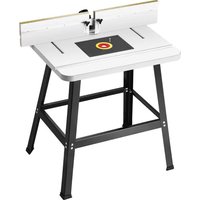
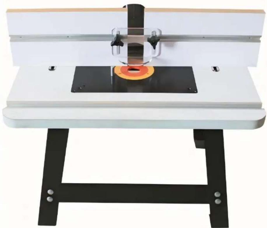
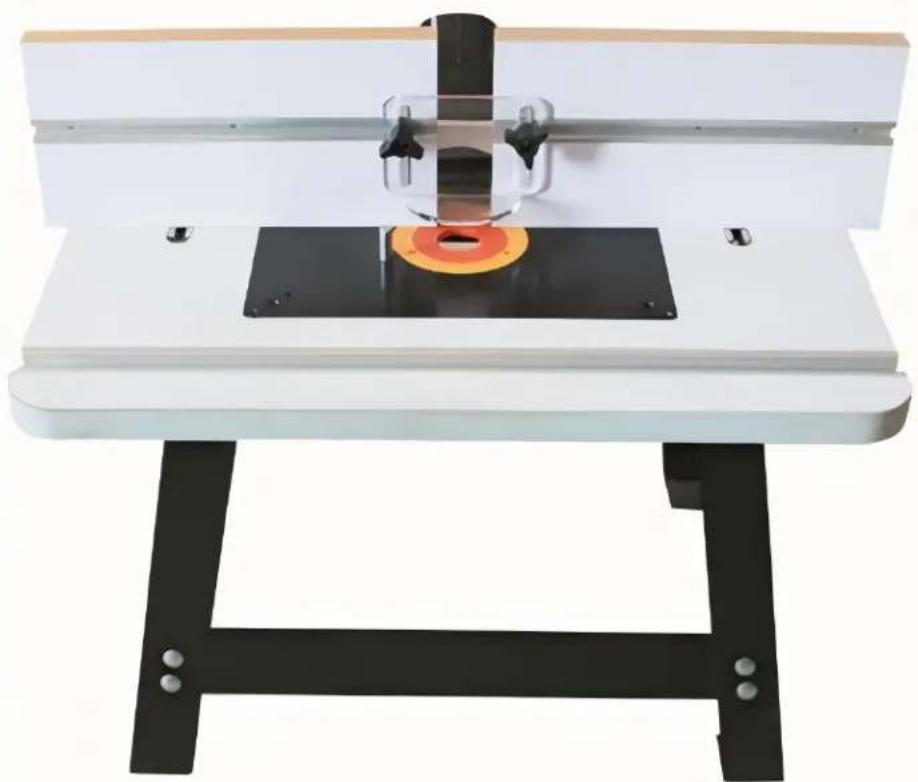
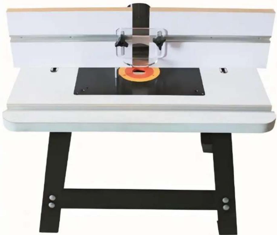
White workbench with black metal frame and orange circular base, no visible text or symbolsThis is the original instruction, please read all manual instructions carefully before operating. VEVOR reserves a clear interpretation of our user manual. The appearance of the product shall be subject to product you received. Please forgive us that we won't inform you ag if there are any technology or software updates on our product.
General Safety Instructions
Extreme caution should be used when operating all power tools. Know your power tool, be familiar with its operation, read through the owner's manual and practice safe usage procedure at all times.
- CONNECT your machine ONLY to the matched and specific power source.
- ALWAYS wear safety glasses respirators, hearing protection and safety shoes, when operating your machine.
- DO NOT wear loose clothing or jewelry when operating your machine.
- A safe environment is important. Keep the area free of dust, dirt an other debris in the immediate vicinity of your machine.
- DISCONNECT the power source when changing drill bits, hollow chisels, router bits, shaper heads, blades, knives or making other adjustments or repairs.
- ALWAYS keep all safety guards in place and ensure their proper function
- NEVER reach over the table when the tool is in operation. It is dangerous.
- ALWAYS keep blades, knives and bits sharpened and properly aligned.
- NEVER leave a tool unattended while it is in operation.
- BE ALERT! DO NOT use prescription or other drugs that may affect your ability or judgment to safely use your machine.
- ALWAYS use push sticks and feather boards to safely feed your work through the machine.
- ALWAYS make sure that any tools used for adjustments are removed before operating the machine.
- Always keep the bystanders safely away while the machine is in operation.
Router Table with Fence & Stand
Specific Safety Instructions
Like all power tools and machinery, proper safety and attention must be adhered to. There is danger associated with using any tool or machine so pay careful attention each and every time you use your tool. If you are not familiar with the operations router table, you should obtain the advice and/or instructions from a qualified professional.
- MAKE SURE the router has been installed securely before staring the machine, for safe operation method.
- NEVER perform any "Free Hand" operation. Do not use your hands to support or guide the work piece. Always use toggle clamp to secure t work piece for cutting.
- DO NOT wear jewelry or loose clothing while operating this machine.
- SAFETY GLASSES & RESPIRATOR is highly recommended when working with this machine. Some sawdust can be harmful to your lungs; please take caution when using this machine.
- ALWAYS feed the work-piece to the router bit against the rotation direction
-
INSPECT your work pieces. Make sure that they are free of nails, staples, tacks, knots and other object that may be harmful to your router I
-
DO NOT jam or try and over push the work piece into the machine during operation. This may cause damage to the machine. Feed the work piece with a firm grasp, slowly and easily and hold the work piece against the fence.
- MAKE SURE the spindle rotates in the correct direction.
- DO NOT let anyone stand in front of the machine while operation.
- TECHNICAL DIFFICULTIES. Any problems you may run into should be carefully looked at with the power OFF and the machine unplugged from the power source.
- NEVER draw the work piece back during the cutting operation. Stop the router bit before drawing back the work-piece.
- ALWAYS keep bits sharpened and clean.
IMPORTANT: The safety instructions given above can not be complete because the environment in every shop is different. Always consider safety first as it applies to your individual working conditions.
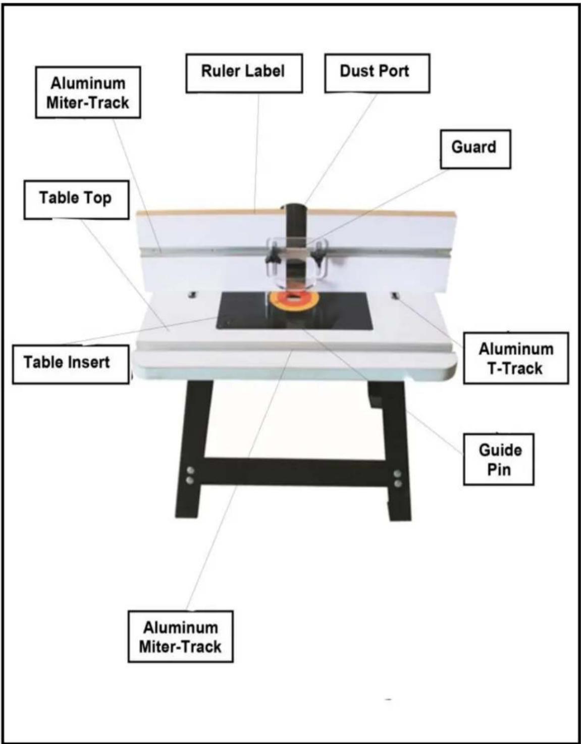
ROUTER TABLE
FEATURES
TABLE TOP
Size: 610*400*25mm
Aluminum Miter Track: 610mm
Table Insert: 306*229mm
FENCE
Size: 305*153mm
Dust Port: 63/77.3/68.2mm
Gaurd: Fluorescent Plastic Plate
Aluminum Miter Track: 305mm
Ruler Label: 300mm
STAND
Made of: Steel
Height: 530mm
PHYSICAL FEATURES
ASSEMBLY & INSTALLATION
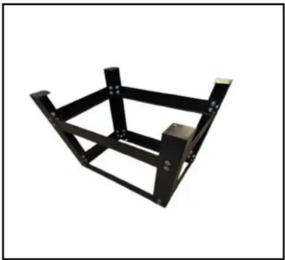
Before assembling the stand, please take Now, mount the two other longer and the a look at the list below. Your stand cometwo short angle braces to the legs with the with the following parts and mounting help of the nuts and bolts, (Finger hardware. Tighten). See Figure-2
- Short Angle Brace: 2-pcs
- Shorter Angle Brace: 2-pcs
- Long Angle Brace: 2-pcs
- Longer Angle Brace: 2-pcs
• Round Head Bolt M8x12: 32-pcs
• Hex Nut M8: 32-pcs - Flat Washer8: 32-pcs
• Hex Bolt M6x16: 4-pcs - Flat Washer: 4-pcs
Stand Assembly
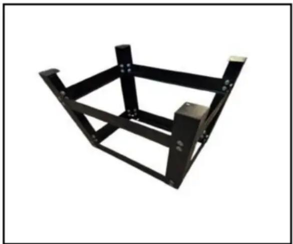
Take the two short and the two longer angle braces out of the box and put it or the floor. Now take the four legs upside Figure-2 down, and attach them to the four braces the legs using 1/4" x 1/2" nuts and bolts. (Finger tighten) See Figure-1.
natural_image
Black metal frame structure with mounting holes and support beams (no text or symbols)Figure-1 Attaching legs to the braces
natural_image
Black metal frame structure with mounting holes and support beams (no text or symbols)Figure-2 Attaching the middle braces to
Now, turn the stand upright and adjust the legs so that they are evenly positioned, tighten all the screws well.
Installing the Router Table on the Stand
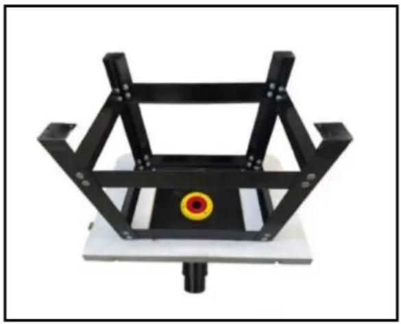
Take the router table and put it upside down on the floor or bench. The router table and the upper braces of the stand feature 4 holes to mount the router table to the stand. Position the stand inverted, on the router table so that the holes are aligned and then mount it with the help of washers and bolts provided, (Finger Tighten). See Figure-3
ASSEMBLY & INSTALLATION
natural_image
Black metal frame structure with a yellow circular marker on top, mounted on a white base (no text or symbols visible)Figure-3 Mounting the stand to the route table
Take the 4 rubber feet out of the pack and attach one on each leg. Now, turn stand up right and your router table is installed on the stand.
Mounting the Router Base Plate in Your Router Table
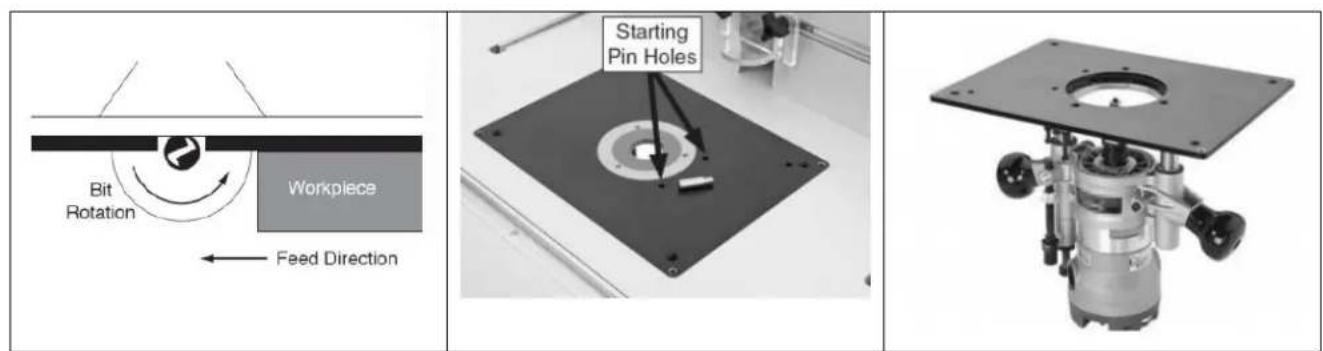
When mounting a large router, the handles should fit in the same direction the long opening. Your current router base plate will function as the drilling jig. However, you should determine the optimum router positioning before the base plate. Make sure to take into account the depth adjustment knobs, depth lock levers/knobs and the location of your switch. Place your router in pro inverted position under the table. Then mark with tape on the front edge of the router's bed plate to verify the position.
Then, remove the screws from the base plate. Locate the top/front of your base plate by observing the position of the starting pin holes. The holes will be to the right of the opening. Again mark with the tape the front and center on the plate to serve as a reminder.
Center the router base plate on the nearest concentric ridge. Then position the mounting holes along the radial lines. Keep the base plate in place with tape. (3 to 4 pieces arranged around the ring should be adequate).
Next, clamp the 2 plates together using C-clamps or wood.
Note: Spring clamps will not provide enough clamping force and could allow the parts to move out of place.
Drill through the new base using a drill bit that matches the size of the holes in your router's base plate.
Note: If available, perform this operation on a drill press to keep the holes perpendicular.
Important: A piece of wood should be clamped to the front of the router plate whole drilling to avoid splintering of the plate.
After removing the clamps, countersink holes similar to the router's own base plate. For best result, we recommend a single flute countersink at a slow speed and a drill press if available.
Finally, mount the base plate to the router. If the screws that came with your router are not long enough, longer screws can be purchased at a hardware store or home center in your area.
If you are unsure about the installation process, p check the installation video.
Bench Top Router Exploded Diagram
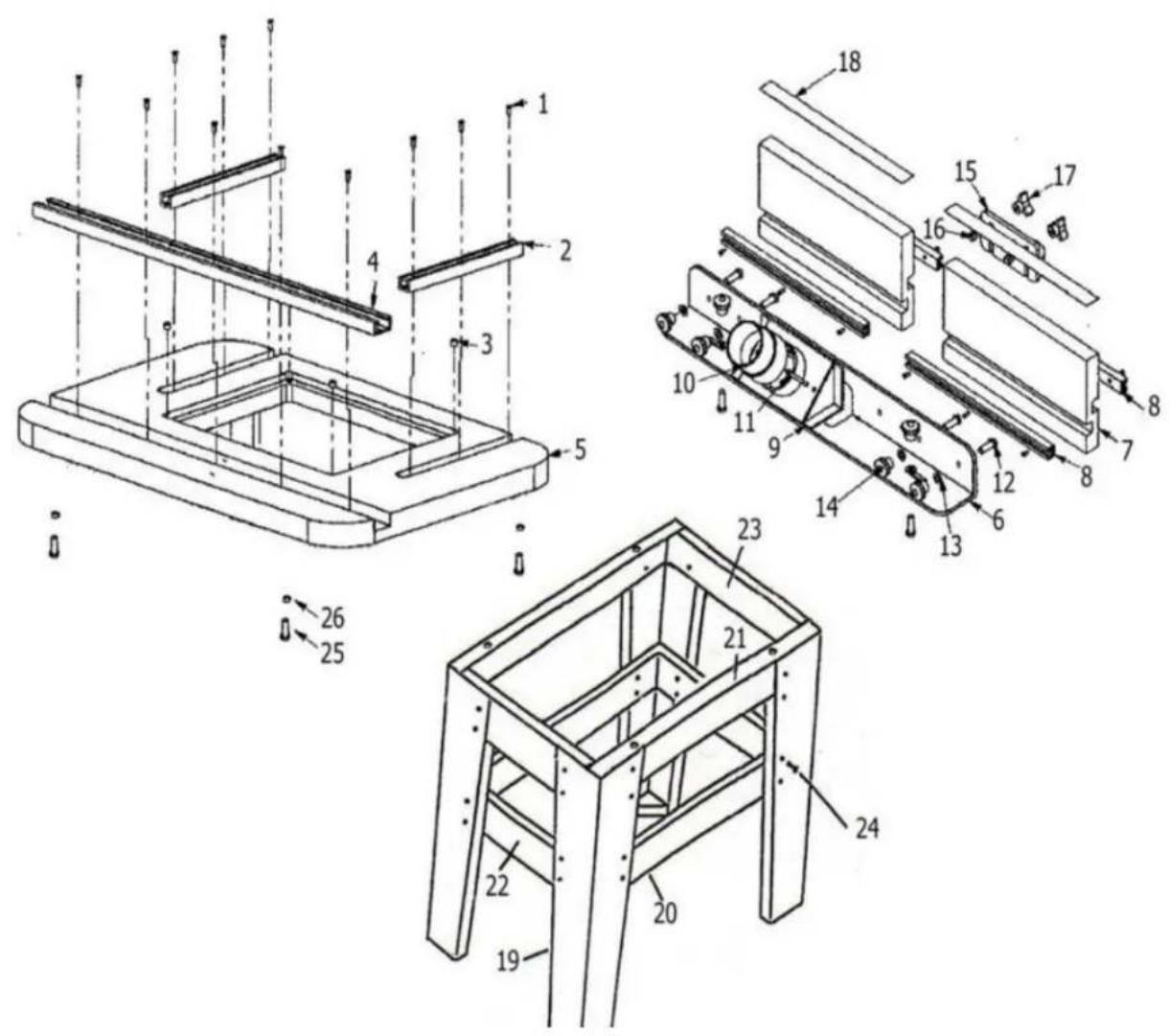
| Part# | Description | Quantity |
| 1 | #5 Self Tapping Screws | 23 |
| 2 | 6-5/8"Aluminum T-Track | 2 |
| 3 | 8mm diameter Magnets | 4 |
| 4 | 24"Aluminum Miter T-Track | 1 |
| 5 | 24"x16"Router Table Top | 1 |
| 6 | L-Aluminum Fence Support | 1 |
| 7 | 12"Melamine Laminated Fences | 2 |
| 8 | 12"Aluminum T-Track | 4 |
| 9 | Dust Port | 1 |
| 10 | 2-1/4"Dust Port Adapter | 1 |
| 11 | M5×0.8x55mm Cross Head Machine Screw | 2 |
| 12 | 8mmx1.25x25mm Hex Bolt | 6 |
| 13 | 8mm Flat Washer | 6 |
| 14 | 8mm Threaded Knob | 6 |
| 15 | Bit Guard | 1 |
| 16 | 6mm x1.0×25mm Hex Bolt | 2 |
| 17 | 6mm Threaded Knob | 2 |
| 18 | Self Stick Measuring Tape | 2 |
| 19 | Stand Leg | 4 |
| 20 | Lower Front/Back Stand Leg Braces | 2 |
| 21 | Upper Front/Back Stand Leg Braces | 2 |
| 22 | Lower Side Stand Leg Braces | 2 |
| 23 | Upper Side Stand Leg Brace | 2 |
| 24 | 8mm×1.25×12mm Carriage Bolt,Flat Washer &Hex Nut | 32 |
| 25 | 6mm x1.0×16mm Hex Bolt | 4 |
| 26 | 6mm Flat Washer | 4 |
Customers need to assemble it by below parts :
| RT017 | Part name | Quantity |
| 1 | 6mm x1.0×16mm Hex Bolt | 4 |
| 2 | 6mm Flat Washer | 4 |
| 3 | Half round head self tapping M4 * 20 * 4 | 4 |
| 4 | Flat Washer | 4 |
| 5 | 8mm Threaded Knob+8mmx1.25x25mm Hex Bolt+8mm Flat Washer | 6 |
| 6 | 6mm Threaded Knob+6mm x1.0×25mm He Bolt+6mm Flat Washer | 2 |
| 7 | M5×0.8x55mm Cross Head Machine Screw | 2 |
| 8 | Position axis | 1 |
| 9 | Self Stick Measuring Tape | 2 |
| 10 | Bit Guard | 1 |
| 11 | Dust Port | 1 |
| 12 | 2-1/4"Dust Port Adapter | 1 |
| 13 | 12"Melamine Laminated Fences | 2 |
| 14 | 24"x16"Router Table Top | 1 |
| 15 | Insert + Guide Pin 9" x 12" | 1 |
| 16 | 24"Aluminum Miter T-Track | 1 |
| 17 | Longer Angle Brace | 2 |
| 18 | Longer Angle Brace | 2 |
| 19 | Short Angle Brace | 2 |
| 20 | Short Angle Brace | 2 |
| 21 | Stand Leg | 4 |
| 22 | M3 hex wrench | 1 |
| 23 | M4 * 16 countersunk cross bolt * 4 (with router screw) | 4 |
| 24 | Round Head Bolt M8 x 12/Hex Nut M8/Washer M8 | 32 |

Technical Support and E-Warranty Certificate www.vevor.com/support
VEVOR
Affordable. Reliable. Home Improvement.
RUTER TABELA
MODEL: RT017
www.vevor.com/support
VEVOR
Affordable. Reliable. Home Improvement.
RUTER TABLE
MODEL: RT017

natural_image
White workbench with black metal frame and orange circular base, no visible text or symbolsnatural_image
Black metal frame structure with support legs and mounting holes (no text or symbols)natural_image
Black metal frame structure with support legs and mounting holes (no text or symbols)natural_image
Black metal frame structure with a yellow circular marker on top, mounted on a white base (no text or symbols visible)Affordable. Reliable. Home Improvement.
RUTER TISCH
MODELL: RT017
www.vevor.com/support
VEVOR
Affordable. Reliable. Home Improvement.
RUTER TABLE
MODELL: RT017
natural_image
White workbench with black metal frame and orange circular base, no visible text or symbolsnatural_image
Black metal frame structure with support legs and mounting holes (no text or symbols)natural_image
Black metal frame structure with support legs and mounting holes (no text or symbols)natural_image
Black metal frame structure with a yellow circular marker on top, mounted on a white base (no text or symbols visible)Affordable. Reliable. Home Improvement.
RUTER TABLEAU
MODÈLE : RT017
Affordable. Reliable. Home Improvement.
RUTER TABLE
MODÈLE : RT017

natural_image
White workbench with black metal frame and orange circular base, no visible text or symbolsnatural_image
Black metal frame structure with mounting holes and support beams (no text or symbols)natural_image
Black metal frame structure with mounting holes and support beams (no text or symbols)natural_image
Black metal frame structure with a yellow circular marker on top, mounted on a white base (no text or symbols visible)Affordable. Reliable. Home Improvement.
RUTER TAFEL
MODEL: RT017
Technische ondersteuning en e-garantiecertificaat www.vevor.com/support
VEVOR
Affordable. Reliable. Home Improvement.
RUTER TABLE
MODEL: RT017

natural_image
White workbench with black metal frame and orange circular base, no visible text or symbolsnatural_image
Black metal frame structure with mounting holes and support beams (no text or symbols)natural_image
Black metal frame structure with support legs and mounting holes (no text or symbols)natural_image
Black metal frame structure with a yellow circular marker on top, mounted on a white base (no text or symbols visible)Affordable. Reliable. Home Improvement.
RUTER TABELL
MODELL: RT017
www.vevor.com/support
VEVOR
Affordable. Reliable. Home Improvement.
RUTER TABLE
MODELL: RT017

natural_image
White workbench with black metal frame and orange circular base, no visible text or symbolsnatural_image
Black metal frame structure with mounting holes and support beams (no text or symbols)natural_image
Black metal frame structure with mounting holes and support beams (no text or symbols)natural_image
Black metal frame structure with a yellow circular marker on top, mounted on a white base (no text or symbols visible)Affordable. Reliable. Home Improvement.
RUTER MESA
MODELO: RT017
Affordable. Reliable. Home Improvement.
RUTER TABLE
MODELO: RT017
natural_image
White workbench with black metal frame and orange circular base, no visible text or symbolsnatural_image
Metal frame structure with mounting holes and support beams (no text or symbols)natural_image
Black metal frame structure with support legs and mounting holes (no text or symbols)natural_image
Black metal frame structure with a yellow circular marker on top, mounted on a white base (no text or symbols visible)Affordable. Reliable. Home Improvement.
ROUTER TAVOLO
MODELLO: RT017
Affordable. Reliable. Home Improvement.
RUTER TABLE
MODELLO: RT017
natural_image
White workbench with black metal frame and orange circular base, no visible text or symbolsnatural_image
Black metal frame structure with support beams and mounting holes (no text or symbols)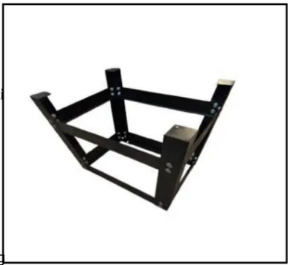
natural_image
Black metal frame structure with mounting holes and support beams (no text or symbols)Figura 2 Allegando IL mezzo bretelle al gambe