USER MANUAL 0700C Vevor
Technical Support and E-Warranty Certificate www.vevor.com/support
ELECTRIC TRIMMER
USR MANUA
MODEL:0700C
We continue to be committed to provide you tools with competitive price. "Save Half", "Half Price" or any other similar expressions used by us only represents an estimate of savings you might benefit from buying certain tools with us compared to the major top brands and does not necessarily mean to cover all categories of tools offered by us. You are kindly reminded to verify carefully when you are placing an order with us if you are actually saving half in comparison with the top major brands
VEVOR®
TOUGH TOOLS, HALF PRICE
ELECTRIC TRIMMER
MODEL:0700C

natural_image
Exterior view of a VEVOR electric drill press tool (no visible text or symbols)

Have product questions? Need technical support? Please feel free to contact us:
Technical Support and E-Warranty Certificate
www.vevor.com/support
This is the original instruction, please read all manual instructions carefully before operating. VEVOR reserves a clear interpretation of our user manual. The appearance of the product shall be subject to the product you received. Please forgive us that we won't inform you again there are any technology or software updates on our product.
Read this operator guide carefully, before using the machine. Ensure that you know how the machine works, and how it should be operated. Maintain the machine in accordance with the instructions, and make certain that the machine functions correctly. Keep this operator's guide and other enclosed documentation with the machine.
TECHNICAL SPECIFICATIONS
| Model | 0700C |
| Rated Voltage | 120V/60Hz 220-240V/50Hz |
| Power | 800w |
| no load speed | 10000-30000/RPM |
| Net weight | 1.8kg |
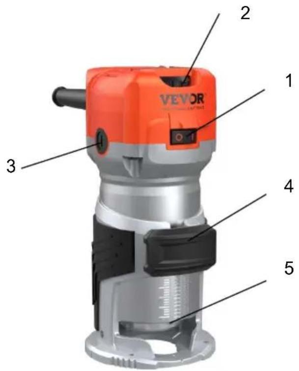
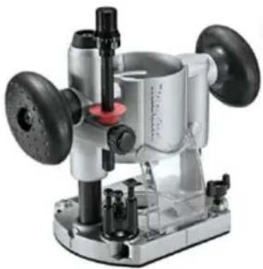
Over view
1.Switch
2.Variable speed
3. Carbon brush cap
4. Locking button
5.LED lamp
This device is exclusively for private use. It is not fit for commercial use.
 | Warning - To reduce the risk of injury, user must read instructions manual carefully. |
 | Warning- Be sure to wear eye protectors when using this product. |
 | This symbol, placed before a safety comment, indicates a kind of precaution, warning, or danger. Ignoring this warning may lead to accident. To reduce the risk of injury, fire, or electrocution, please always follow the recommendation shown below. |
 | Alternating current |
 | This product is of protection class II. That means it is equipped with enhanced or double insulation. |
 | FCC information: This device complies with Part 15 of the FCC Rules. Operation is subject to the following two conditions:(1)This device may not cause harmful interference, and (2)this device must accept any interference received, including interference that may cause undesired operation. |
 | Disposal information: This product is subject to the provision of European Directive 2012/19/EC. The symbol showing a wheelie bir crossed through indicates that the product requires separate refuse collection in the European Union. This applies to the product and accessories marked with this symbol. Products marked as such may not be discarded with normal domestic waste, but must be taken collection point for recycling electrical and electronic devices |

WARNING! Read all instructions. Failure to follow all instructions listed below may result in electric shock, fire and/or serious injury:
SAVE THESE INSTRUCTIONS FOR FUTURE REFERENCE.
1) Work area safety
Keep the work area clean and well-lit. Cluttered and dark areas invite accidents.
Do not operate machines in explosive atmospheres, such as in the presence of flammable liquids, gases, or dust. Machines create sparks that may ignite dust or fumes.
Keep children and bystanders away while operating a machine.
Distractions can cause you to lose control.
2) Electrical safety
Machine plugs must match the outlet. Never modify the plug in any way. not use any adapter plugs with earthed (grounded) machines. Unmodified plugs and matching outlets will reduce risk of electric shock.
- Avoid body contact with earthed or grounded surfaces such as pipes, radiators, ranges and refrigerators. There is an increased risk of electric shock if your body is earthed or grounded.
- Do not expose machines to rain or wet conditions. Water entering a machine will increase the risk of electric shock.
- Do not abuse the cord. Never use the cord for carrying, pulling or unplugging the machine. Keep cord away from heat, oil, sharp edges or moving parts. Damaged or entangled cords increase the risk of electric shock.
- When operating a machine outdoors, use an extension cord suitable for outdoor use. Use of a cord suitable for outdoor use reduces the of electric shock.
- If operating a power tool in a damp location is unavoidable, use a residual current device (RCD) protected supply. Use of an RCD reduces the risk of electric shock.
3) Personal safety
- Stay alert. Watch what you are doing and use common sense when operating a machine. Do not use a machine while you are tired or under the influence of drugs, alcohol or medication. A moment of inattention while operating machines may result in serious personal injury.
- Use safety equipment. Always wear eye protection. Safety equipment
such as dust marks, non-skid safety shoes, hard hats, or hearing protection used for appropriate conditions will reduce personal injuries.
- Avoid accidental starting. Ensure the switch is in the off position before plugging it in. Carrying machines with your finger on the switch or plugging in machines that have the switch on invites accidents.
- Remove any adjusting key or wrench before turning the machine on. A wrench or a key left attached to a rotating part of the machine may result in personal injury.
- Do not overreach. Keep proper footing and balance at all times. This enables better control of the machine in unexpected situations.
- Dress properly. Do not wear loose clothing or jewellery. Keep your hair clothing and gloves away from moving parts. Loose clothes, jewellery or long hair can be caught in moving parts.
- If devices are provided for the connection of dust extraction and collection facilities, ensure these are connected and properly used. Use of these devices can reduce dust related hazards.
- Do not let familiarity gained from frequent use of tools allow you to become complacent and ignore tool safety principles. A careless action can cause severe injury within a fraction of a second.
4) Machine use and care
- Do not force the machine. Use the correct machine for your application. The correct machine will do the job better and safer at the rate for which it was designed.
- Do not use the machine if the switch does not turn it on and off. Any machine that can not be controlled with the switch is dangerous and must be repaired.
- Disconnect the plug from the power source before making any adjustments, changing accessories, or storing machines. Such preventive safety measures reduce the risk of starting the machine accidentally.
-
Store idle machines out of the reach of children and do not allow persons unfamiliar with the machine or these instructions to operate the machine. Machines are dangerous in the hands of untrained user
-
Maintain machines. Check for misalignment or binding of moving parts, breakage of parts and any other condition that may affect the machine's operation. If damaged, have the machine repaired before use. Many accidents are caused by poorly maintained machines.
- Keep cutting tools sharp and clean. Properly maintained cutting tools with sharp cutting edges are less likely to bind and are easier to control.
- Use the machine, accessories and tool bits, etc., in accordance with these instructions and in
The manner intended for the particular type of machine, taking into account the working conditions and the work to be performed. Use of the machine for operations different from intended could result in a hazardous situation
- Keep handles and grasping surfaces dry, clean and free from oil and grease. Slippery handles and grasping surfaces do not allow for safe handling and control of the tool in unexpected situations.
5) Service
- Have your machine serviced by a qualified repair person using only identical replacement parts.
This will ensure that the safety of the machine is maintained.
- Maintain labels and nameplates on the tool. These carry important safety information. If unreadable or missing, contact VEVOR for a replacement.
- Type Y attachment: If the supply cord is damaged, it must be replaced by the manufacturer, its service agent or similarly qualified persons in order to avoid a hazard.
OPERATION INSTRUCTIONS
Adjust bit protrusion
1b adjust the bit protrusion, loosen the locking lever and move the tool base up or down as desired by turning the,adjusting screw. After adjusting tighten the locking lever firmly to secure the tool base.
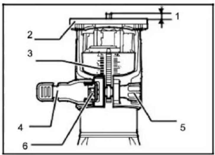
I.bit protrusion
2. tool base
3. scale
4. locking lever
5. adjusting screw
6. hex nut
Switch action
To start the tool, press the ON (I) "side of the switch. To stop the tool, press the OFF(0)" side of the switch.
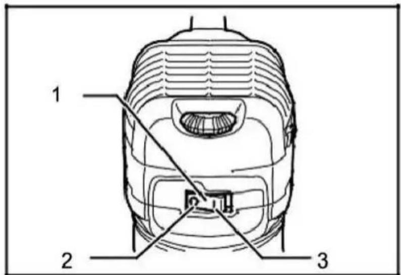
1 .Switch
2.OFF(O) side
3.ON(I)side
Speed adjusting dial
The tool speed can be changed by turning the speed and adjusting the dial to the given number setting from 1 to 6. Higher speed is obtained when the dial is turned in the direction of number 6. And lower speed is obtained when it is turned in the direction of number
This allows the ideal speed to be selected for optimum material processing, the speed can be correctly adjusted to suit the material and bit diameter. Refer to the table for the relationship between the number
settings on the dial and the approximate tool speed.
| Number | RPM |
| 1 | 10000 |
| 2 | 13000 |
| 3 | 17000 |
| 4 | 21000 |
| 5 | 25000 |
| 6 | 30000 |
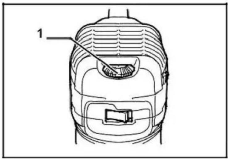
- Speed adjusting dial
Installing or removing trimmer bit
Insert the bit all the way into the collect cone and tighten the collect nut security with the two wrenches or by pressing the shaft lock and using t provided wrench, lb remove the bit, and follow the installation procedure reverse.
- Tighten
- Loosen
- Hold
Operation with straight guide
The straight guide is effectively used for straight cuts when chamfering or grooving. Attach the guide plate to the straight guide with the bolt and the wing nut. Attach the straight guide with the clamp screw (A). Loosen the wing nut on the straight guide and adjust the distance between the bit at the straight guide. At the desired distance, tighten the wing nut securely.
Circular work
The straight guide is effectively used for straight cuts when chamfering or grooving. Attach the guide plate to the straight guide with the bolt and the wing nut. Attach the straight guide with the clamp screw (A). Loosen the wing nut on the straight guide and adjust the distance between the bit a the straight guide. At the desired distance, tighten the wing nut securely.
1.Bolt
-
Guide plate
-
Straight guide
4.Wing nut
-
Clamp screw (A)
-
Straight guide
3.Wing nut
4.Base
Circular work
Circular work may be accomplished if you assemble the straight guide arguide plate as shown in the figures. Min and Max radius of circles to be (distance between the center of circle and the center of bit) are as follow
Min: 70 ~mm (2 - 3 / 4 ~B)
Max: 221mm (8-11/16")
-
Wing nut
-
Guide plate
-
Straight guide
-
Center holder
5.Bolt
Trimmer guide
Trimming, curved cuts in veneers for furniture and the like can be done easily with the trimmer guide. The guide roller rides the curve and assure a fine cut. Install the trimmer guide on the tool base with the clamp screw (A). Lochen the clamp screw(B) and adjust the distance between the bit and the trimmer guide by turning the adjusting screw. At the desired distance, tighten the clamp screw(B) to secure the trimmer guide in place. When cutting, move the tool with the guide roller riding the side of the workpiece.
- Clamp screw(A)
- Adjusting screw
- Clamp screw (B)
- Trimmer guide
- Workpiece
2 .Bit
- Guide roller
Overload
The motor of your electric router may be damaged when overloaded. This results from excessive working pressure over a prolonged period. Therefore you should not try to accelerate your working speed by increasing pressure on your machine.
Replacing carbon brush
Remove and check the carbon brushes regularly. Replace them when the wear down to limited mark. Keep the carbon brushes clean and free to into the holders. Both carbon brushes should be replaced at the same time.
Use only identical carbon brushes.
Use a screwdriver to remove the brush holder caps. Take out the worn carbon brushes, insert the new ones and secure the brush holder caps, maintain product SAFETY and RELIABILITY repairs, any other maintenance or adjustment should be performed by authorized service centers, always using replacement parts.
-
Screwdriver
-
Brush holder cap
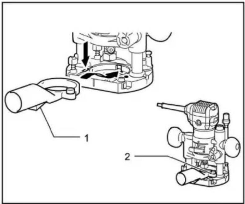
OPERATION
For trimming machine base
- Dust collector
- Butterfly screw
- Trimming machine base

Be careful
- When used as an engraving machine, please hold the tool tightly with both hands.
natural_image
Technical line drawing of a mechanical device with internal components and labeled part 1 (no text or symbols beyond label)
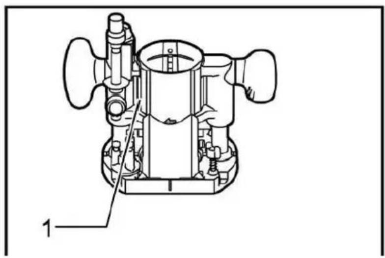
1.Screw
2.Knob handle
3. Offset base plate
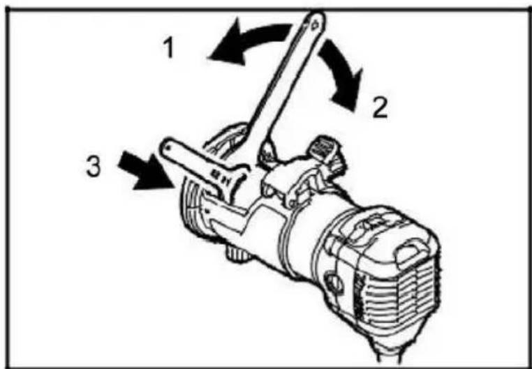
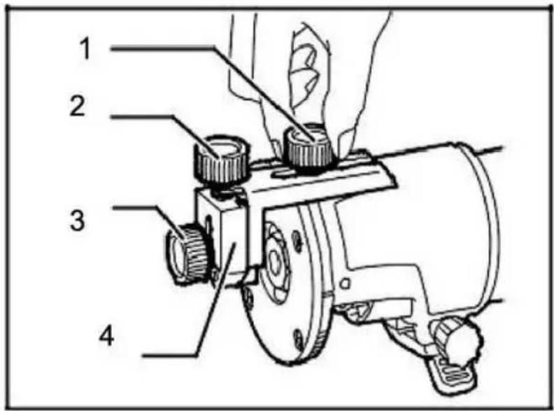
When using this tool as an engraving machine, please press the tool fully into the cut-in base(optional accessories) for installation. According to the operation situation, you can use knob handle or rod handle (optional accessories).
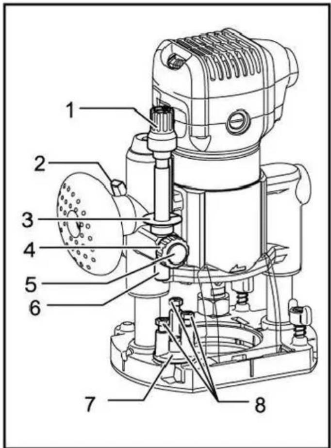
- Adjusting knob
- Locking lever
3.Depth pointer
- Stopper rod setting n
- Quick feed button
- Stopper rod
- Stopper lock
- Adjusting bolt
Place the tool on a flat surface. Loosen the locking lever and lower the body until the cutter head just touches the flat surface. Tighten the lockir lever to lock the fuselage.
Turn the stop lever, setting nut counterclockwise. Lower the stopper rod until it contacts the adjusting bolt. Set depth pointer.
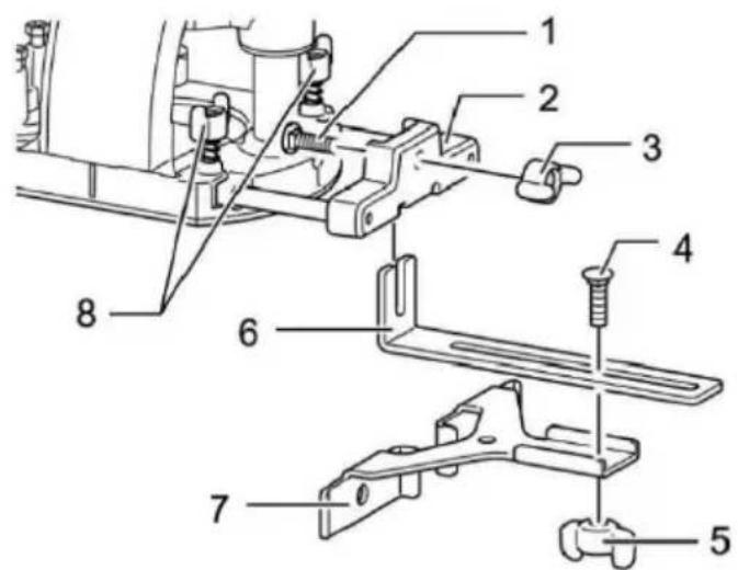
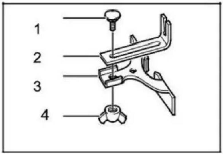
1.Bolt
2. Guide plate support
3. Butterfly nut
4.Bolt
5. Butterfly nut
6. Guide plate
7.Linear guide
8. Butterfly bolt
Install the straight guide to the guide bracket with the butterfly nut (option
accessories). Insert the guide bracket into the hole on the cut-in base and tighten the butterfly bolt. To adjust the distance between the cutter head and the linear guide, loosen the butterfly nut. After the required distance reached, tighten the butterfly nut to fix the linear guide in place.
Linear guide (optional accessories)
natural_image
Illustration of a hand operating a mechanical tool on a workbench, with an arrow indicating motion (no text or symbols present)
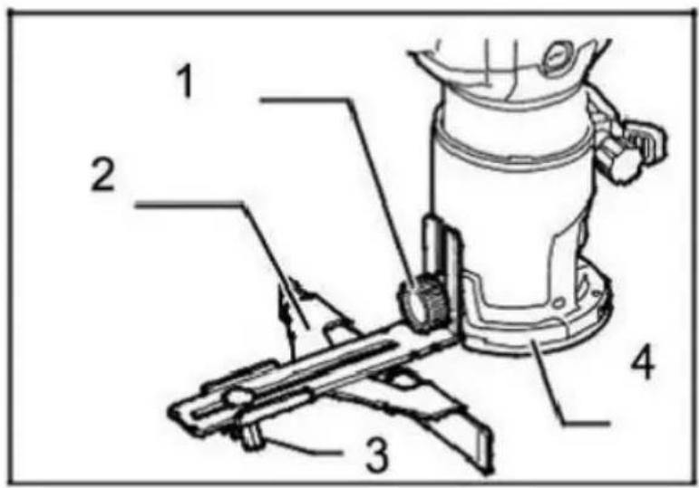
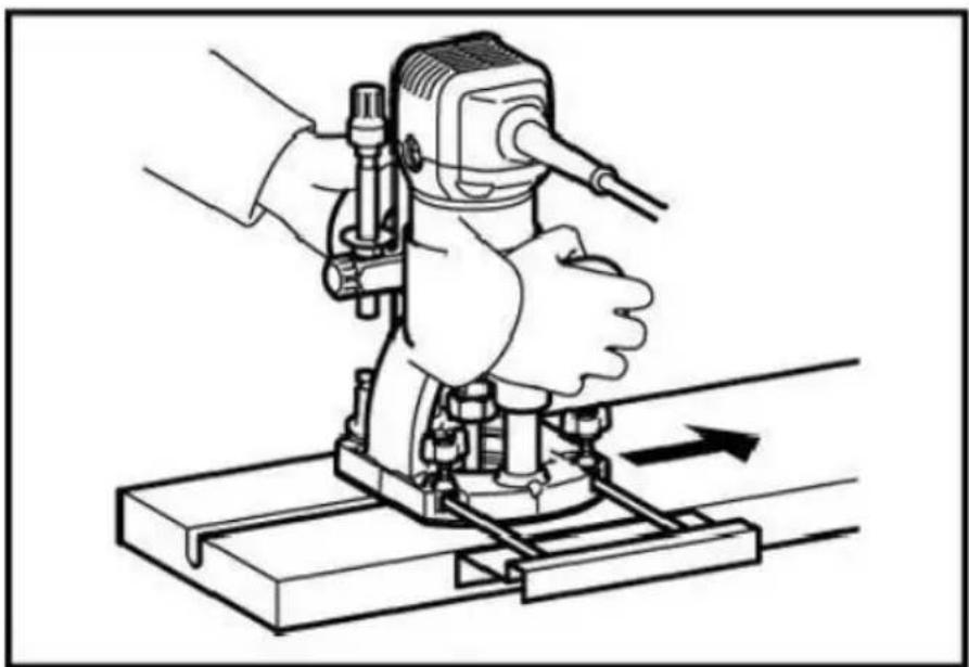
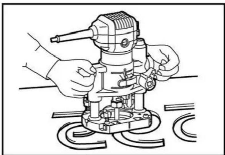
When oblique planing or slotting, the use of linear guide plate for linear cutting is particularly effective.
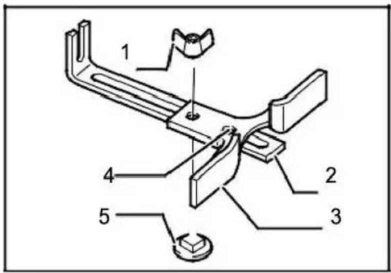
Sample gauge guide plate (optional accessories)
natural_image
Line drawing of a manual electric drill press with hands operating it (no text or symbols present)
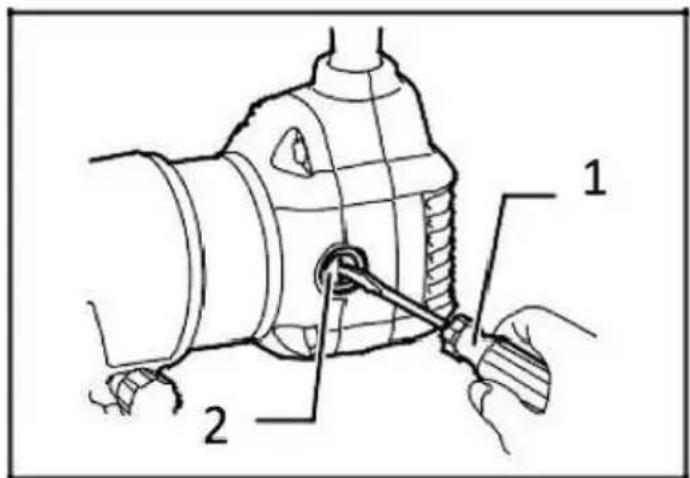
The sample gauge guide has a sleeve for the cutter head to pass through allowing the use of tools with sample gauge mode. When installing the
sample gauge guide plate,please loosen the screw on the tool base,inse the sample gauge guide plate,and then tighten the screw.
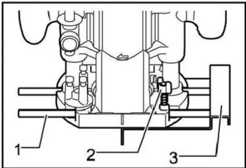
-
Guide rod
-
Butterfly bolt
-
Linear guide
When installing the straight guide, insert the guide rod into the hole on the cut-in base. Adjust the distance between the cutter head and the linear guide plate. When the required distance is reached, tighten the butterfly bolts to fix the straight guide plate in place. When cutting, move the tool when the linear guide is flush with one side of the workpiece.
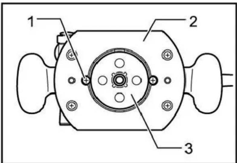
-
Screw
-
Pedestal
-
Sample gauge
Fasten the sample gauge on the workpiece. Place the tool on the sample gauge and move the tool while sliding the guide plate of the sample gau along the side of the sample gauge.
natural_image
Technical line drawing of a mechanical machine with no visible text or symbols
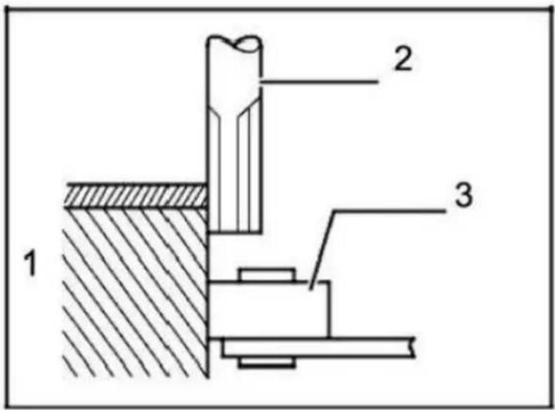
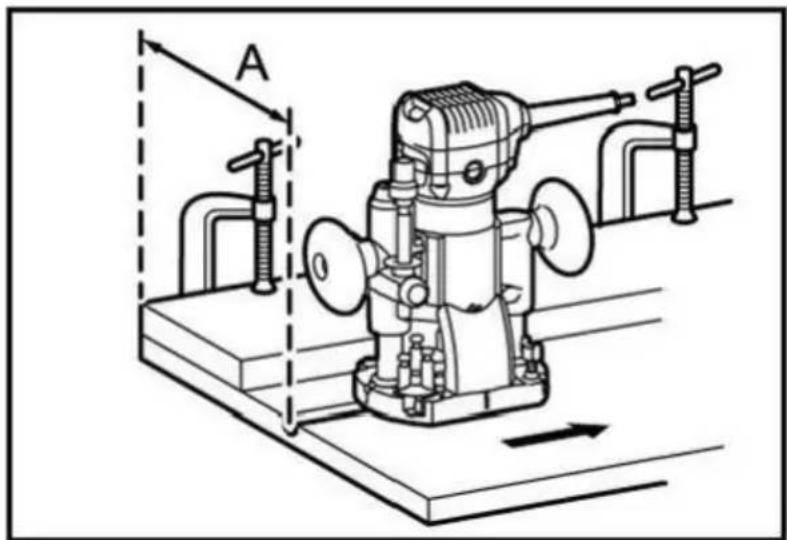
If the distance(a)between one side of the workpiece and the cutting position is too wide for the linear guide,or if one side of the workpiece is straight,the linear guide cannot be used.In this case,a straight guide plate can be firmly clamped to the workpiece and held against the base of the engraving machine as a guide plate.Feed the tool in the direction of the arrow.

natural_image
Technical line drawing of a mechanical machine with labeled component A and directional arrow (no text or symbols beyond labels)
- Cutter head
- Pedestal
3.Sample gauge
4.workpiece
- Distance(X)
- Outer diameter of sample gauge guide plate
- Sample gauge guide
Notes: The workpiece will be cut in a slightly different size from the same gauge.Leave a certain distance(x)between the cutter head and the outside of the sample gauge guide plate.The distance(x)can be calculated using the following equation.Distance(x)=(outer diameter of sample gauge guide plate-cutter head diameter)12
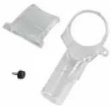
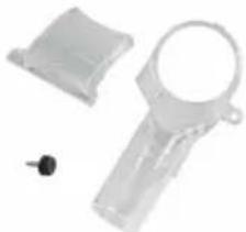
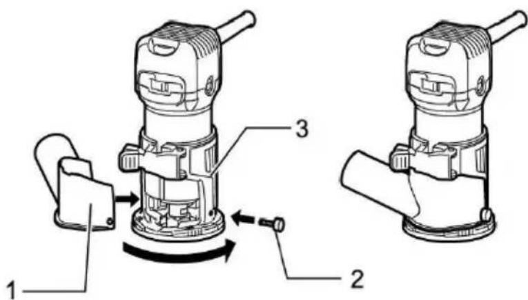
For cut in base(optional accessories)
-
Dust collector
-
Butterfly screw
Use the dust collector to remove dust. Use butterfly screws to install the dust collection port on the tool base, so that the convex part on the dust collection port is embedded in the groove on the tool base. Then, connect the hose of the vacuum cleaner to the dust collection port.
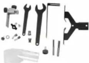
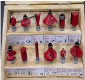
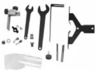
Standard configuration
- 6.35mm milling cutter
- 8mm milling cutter
- Guide as-straight
- Guide as-finisher
- Trimming machine base assembly
- 13 wrench
- 22 wrench
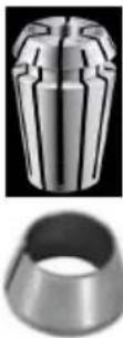
- 6.35mm tapered collet
- 8mm tapered collet
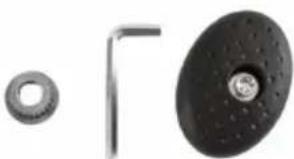
Purchase accessories
- Tilt base assembly
- Cut in base assembly
- Offset base assembly
- 6mm tapered collet
● 9.53mm tapered collet
VEVOR®
TOUGH TOOLS, HALF PRICE
Technical Support and E-Warranty Certificate
www.vevor.com/support
VEVOR®
natural_image
Exterior view of a Vevor electric drill press machine (no visible text or symbols)

natural_image
Technical line drawing of a mechanical device with labeled component (no text or symbols present)
-
Boulon
-
Support de plaque de guidage
-
Écrou papillon 4.
Boulon
- Écrou papillon 6.
Plaque de guidage 7.
natural_image
Illustration of a hand operating a mechanical tool on a workbench, with no visible text or symbols.
natural_image
Line drawing of a mechanical tool with hands operating it, no text or symbols present
natural_image
Technical line drawing of a mechanical device with labeled section A, showing no text or symbols beyond the label 'A'
natural_image
Technical line drawing of a mechanical machine with no visible text or symbols
natural_image
Exterior view of a Vevor electric drill press machine (no visible text or symbols)


I.bit-Vorsprung
natural_image
Technical line drawing of a mechanical device with labeled component (no text or symbols present)
- Einstellknopf 2.
Feststellhebel 3.
Tiefenanzeige 4.
1.Bolzen
natural_image
Illustration of a hand operating a mechanical tool on a workbench, with no visible text or symbols.
natural_image
Line drawing of a mechanical device with hands operating it, no text or symbols present
natural_image
Technical line drawing of a mechanical device with labeled component 'A' and directional arrow (no text or symbols beyond label)
natural_image
Technical line drawing of a mechanical device with labeled component 'A' and directional arrow (no text or symbols beyond label)
ÿ 22 Schraubenschlüssel
www.vevor.com/support
VEVOR®
natural_image
Exterior view of a Vevor electric shaver with orange and silver casing (no visible text or symbols)

natural_image
Technical line drawing of a mechanical device with internal components and labeled part (1), no readable text or symbols beyond the label.
natural_image
Illustration of a hand operating a mechanical tool on a workbench, with no visible text or symbols.
natural_image
Line drawing of a mechanical tool with hands operating it, no text or symbols present
natural_image
Technical line drawing of a mechanical device with labeled component 'A' and directional arrow (no text or symbols beyond label)
natural_image
Technical line drawing of a mechanical device with labeled section A, showing internal components and motion direction (no text or symbols)
- Testa di taglio
2.Piedistallo
3.Calibro campione
4.Pezzo da
natural_image
Exterior view of a VEVOR electric drill press machine (no visible text or symbols)

I.protrusión de bit
-
Destornillador
-
Tapa del portaescobillas
OPERACIÓN
- Colector de polvo
2.Tornillo de mariposa
natural_image
Technical line drawing of a mechanical device with labeled component (no text or symbols present)
1.Tornillo
2.Manija de la perilla
3. Placa base desplazada
- Perilla de ajuste 2.
natural_image
Illustration of a hand operating a mechanical tool on a workbench, with no visible text or symbols.
natural_image
Line drawing of a mechanical tool with hands operating it, no text or symbols present
natural_image
Technical line drawing of a mechanical device with labeled section A, showing no text or symbols beyond the label
natural_image
Technical line drawing of a mechanical machine with no visible text or symbols
-
Colector de polvo
-
Tornillo de mariposa
natural_image
Exterior view of a VEVOR electric drill press tool (no visible text or symbols)

POTRZEBUJESZ POMOCY? SKONTAKTUJ SIĘ Z NAMI!
Występ I.bit
natural_image
Technical line drawing of a mechanical device with labeled component (no text or symbols present)
natural_image
Illustration of a hand operating a mechanical tool on a workbench, with an arrow indicating direction (no text or symbols present)
natural_image
Line drawing of a mechanical tool with hands operating it, no text or symbols present
natural_image
Technical line drawing of a mechanical device with labeled component A, showing no text or symbols beyond the label 'A'
natural_image
Technical line drawing of a mechanical machine with no visible text or symbols
natural_image
Exterior view of a Vevor electric drill press machine (no visible text or symbols)


natural_image
Technical line drawing of a mechanical device with labeled component (no text or symbols present)
- Instelknop 2.
Vergrendelingshendel
- Dieptewijzer 4.
Instelmoer stopstang 5.
Snelvoedingsknop
-
Stopstang
-
Stopvergrendeling
8.Afstelbout
natural_image
Illustration of a hand operating a mechanical tool on a workbench, with an arrow indicating direction (no text or symbols present)
natural_image
Line drawing of a mechanical tool with hands operating it, no text or symbols present
natural_image
Technical line drawing of a mechanical device with labeled component A, showing no text or symbols beyond the label 'A'
natural_image
Technical line drawing of a mechanical machine with no visible text or symbols
www.vevor.com/support
VEVOR®
natural_image
Exterior view of a Vevor electric drill press machine (no visible text or symbols)


BEHÖVER HJÄLP? KONTAKTA OSS!
www.vevor.com/support
I.bit utsprång
2.verktygsbas
-
skala
-
lässpak
-
justerskruv
-
sexkantsmutter
Växla åtgärd
- Klämskruv (A)
2.Rak guide
- Vingmutter
4.Bas
Cirkulärt arbete
-
Skruvmejsel
-
Borsthållarlock
DRIFT
natural_image
Technical line drawing of a mechanical device with labeled component (no text or symbols present)
1.Skruva
2. Knopphandtag
3. Offset bottenplatta
- Justeringsvred 2.
Låsspak 3.
Djupvisare 4.
1.Bult
natural_image
Illustration of a hand operating a mechanical tool on a workbench, with an arrow indicating motion (no text or symbols present)
natural_image
Line drawing of a mechanical tool with hands operating it, no text or symbols present
natural_image
Technical line drawing of a mechanical device with labeled component 'A' and directional arrow (no text or symbols beyond label)
natural_image
Technical line drawing of a mechanical device with no visible text or symbols
-
Dammuppsamlare
-
Fjärilsskruv
www.vevor.com/support