
V68PHL4B0 - Cooker NEFF - Free user manual and instructions
Find the device manual for free V68PHL4B0 NEFF in PDF.
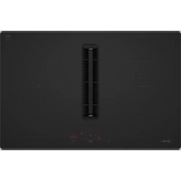


| Product Type | Cooker with integrated hood |
| Brand | NEFF |
| Model | V68PHL4B0 |
| Net weight | max. 25 kg |
| Electrical supply | 230-240 V, 50 Hz |
| Connection types | 1N, 2N, 3N, 2L/2N |
| Extraction functions | Yes, integrated fan motor |
| External extraction mode | Yes, requires duct and backflow damper |
| Air recirculation mode | Yes, with adapter and odour filters |
| Grease filter | Yes, removable and washable |
| Odour filter | Yes, for recirculation mode |
| Acoustic filter | Yes, for external extraction mode |
| Duct diameter | 150 mm (round) |
| Required ventilation | Air outlet min. 200 cm² (worktop) and 400 cm² (baseboard) |
| Installation | Installation in worktop, flush mount possible |
| Safety | Permanent magnets; minimum distance 10 cm for implant wearers |
| Maintenance and cleaning | Regular cleaning of filters, silicone seals after installation |
| Supplied accessories | Seals, retaining brackets, filters, adapter (depending on mode) |
| Repairability | Spare parts available via after-sales service; installation by professional |
| General information | User and installation manual available as PDF |
Frequently Asked Questions - V68PHL4B0 NEFF
User questions about V68PHL4B0 NEFF
0 question about this device. Answer the ones you know or ask your own.
Ask a new question about this device
Download the instructions for your Cooker in PDF format for free! Find your manual V68PHL4B0 - NEFF and take your electronic device back in hand. On this page are published all the documents necessary for the use of your device. V68PHL4B0 by NEFF.
USER MANUAL V68PHL4B0 NEFF
Therefore, m = 3/11.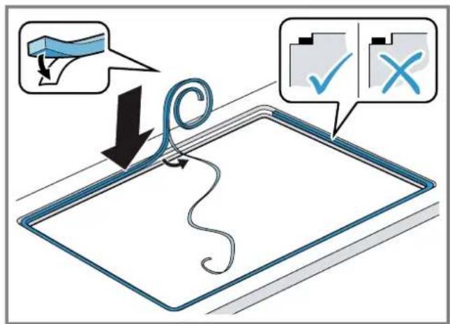
25
26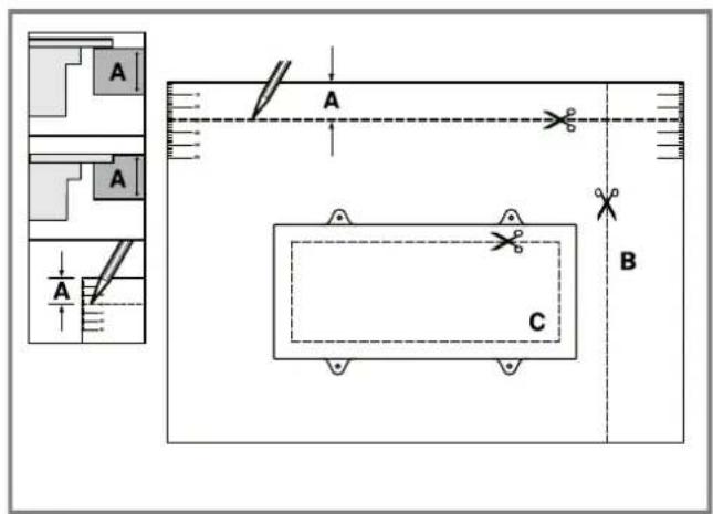
25
27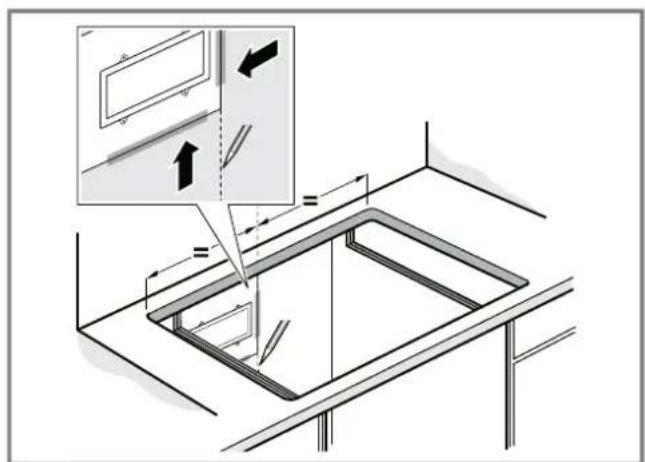
28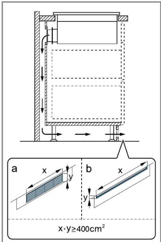
29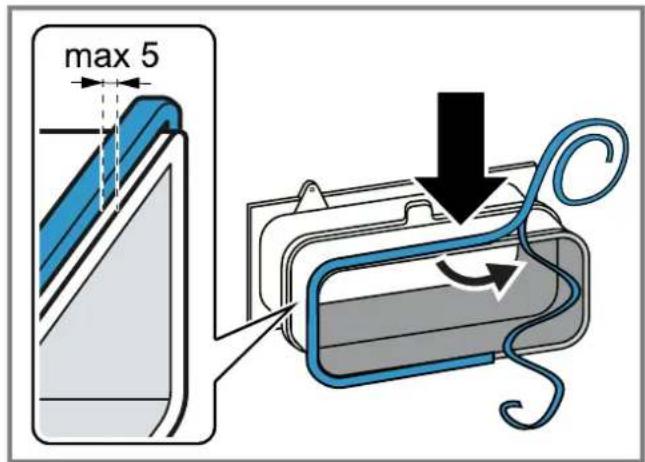
30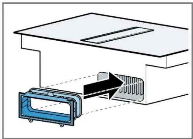
31
Therefore, m = 3/11.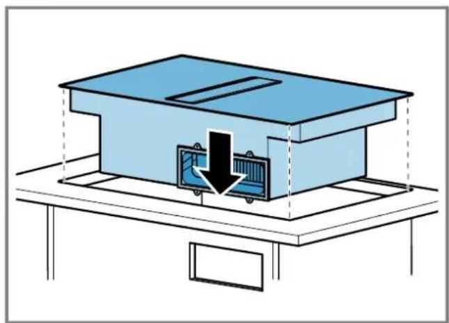
33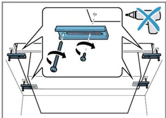
35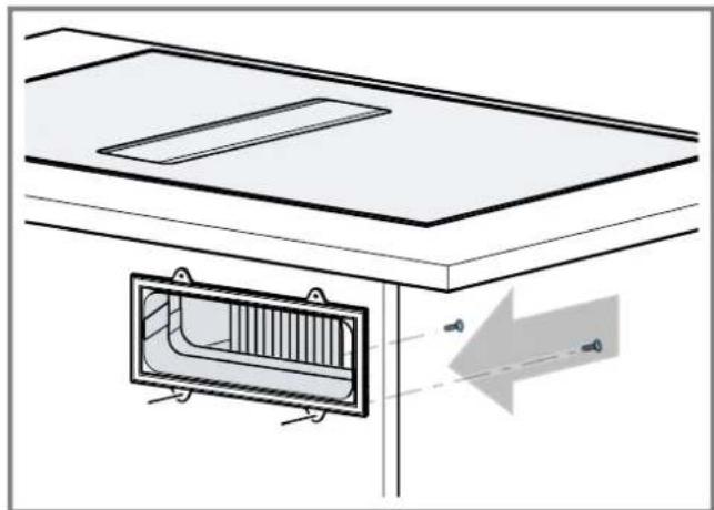
36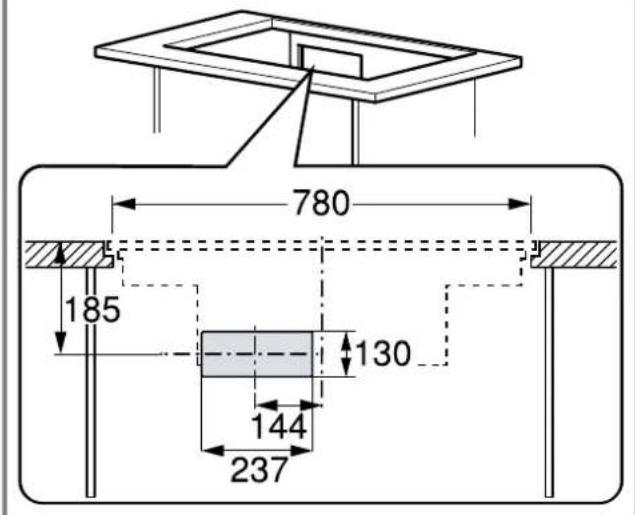
37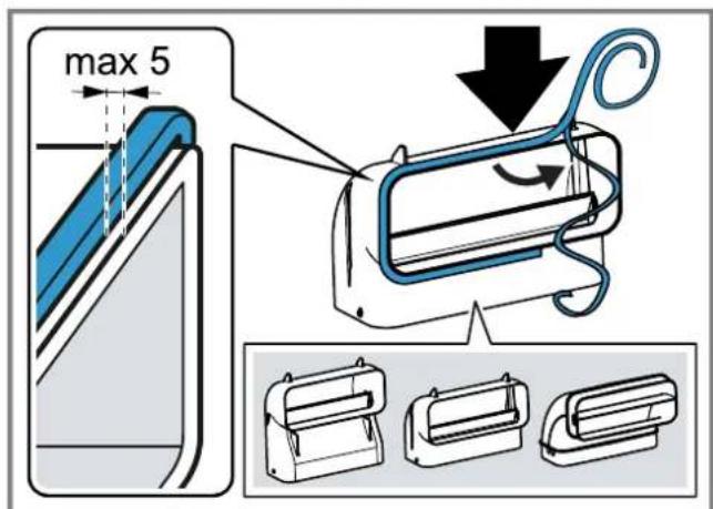
Therefore, m = 3/11.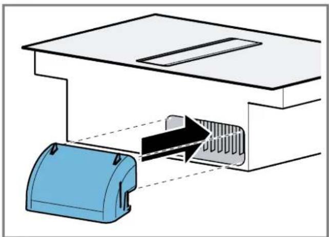
39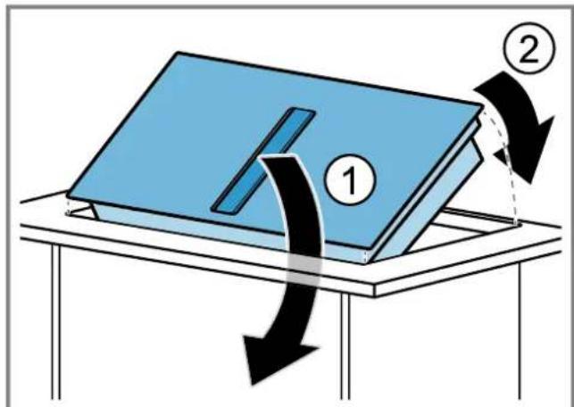
41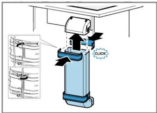
Therefore m = 3/11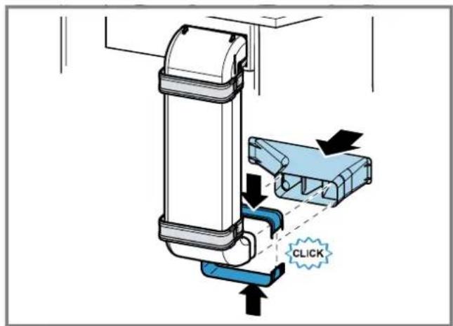
43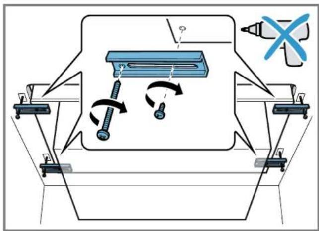
44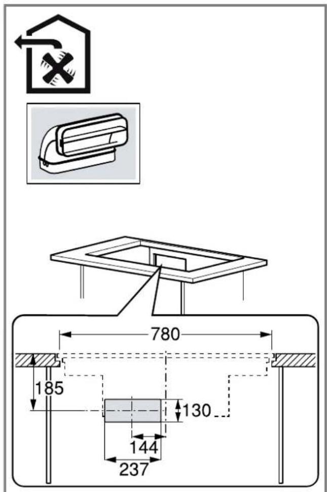
45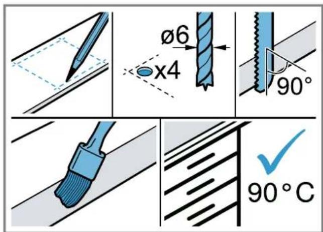
Therefore m = 3/11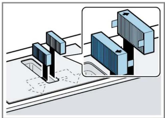
47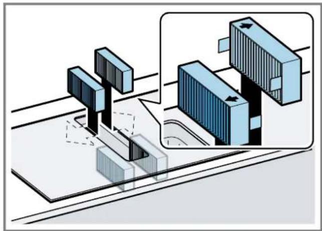
1/2 =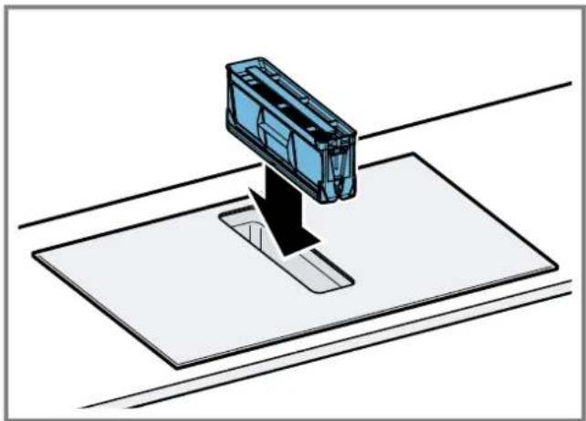
49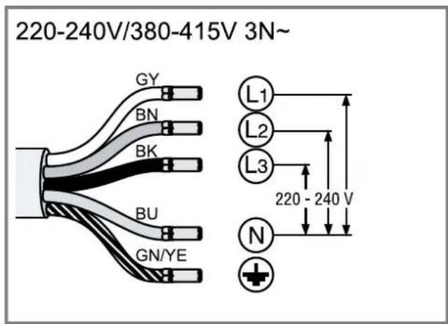
Therefore m = 3/11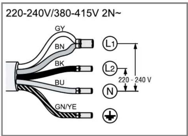
51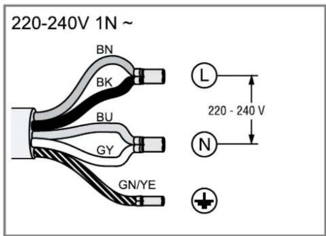
Therefore m = 3/11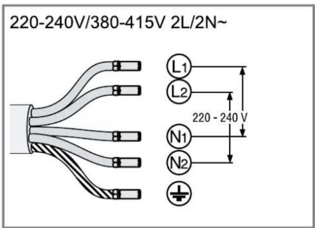
53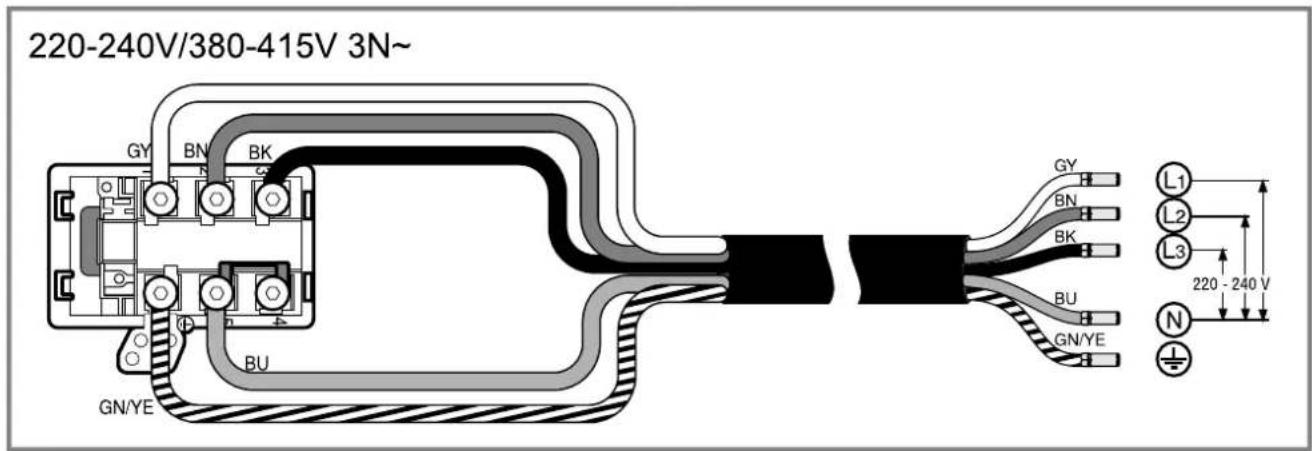
220-240V/380-415V 2N~
220-240V 1N~
After unpacking all parts, check for any damage in transit and completeness of the delivery. (See Fig. 1)
QR code for the installation video
This is where you will find the QR code for the installation video.
(See Fig. 2)
Appliance dimensions
You will find the dimensions of the appliance here.
(See Fig. 3)
Installation dimensions for flat duct bends
This is where you can find an overview of the installation dimensions for the flat duct bends.
Side view:
→ Fig. A → Fig. F → Fig. H1 → Fig. F
Front view:
→ Fig. 7
Installation variants
This is where you can find an overview of the different installation variants.
Odour filter and adapter for circulating-air mode:
→ Fig. 8
Acoustics filter and seal for air extraction mode: → Fig. 9
Note: Channels suitable for installation can be obtained from customer service, our website or from specialist retailers.
Safety clearances
Comply with the safety clearances for the appliance. Clearances to the overflow container:
→ Fig. 10
Position of the overflow container:
→ Fig. 11
The performance is optimal at a clearance of 50 mm between the unit back panel and the wall. The performance is reduced at a smaller clearance.
→ Fig. 12
Observe the safety clearances for the worktop cutout.
Do not place any objects in the drawer which exceed the maximum height of the drawer. The objects may come into contact with the base of the appliance and thus disrupt the functions.
→ Fig. 13

General information
- Read this instruction manual carefully. Only a licensed expert may connect the appliance.
- Switch off the power supply before carrying out any work.
- Never use this appliance in boats or in vehicles.
- Follow the worktop manufacturer's recommendations.
Safe installation
Follow these safety instructions when installing the appliance.
The appliance can only be used safely if it is correctly installed according to the safety instructions. The installer is responsible for ensuring that the appliance works perfectly at its installation location.
Note: This appliance is designed to capture steam from cookware on the cooking zone. If the vapours are captured by other appliances (such as universal kitchen machines or hobs), the efficiency of the ventilation system depends on the distance between the air inlet and the source of the vapours.
WARNING - Danger: Magnetism!
The appliance contains permanent magnets. They may affect electronic implants, e.g. pacemakers or insulin pumps.
- Persons with electronic implants must stand at least 10 cm away from the appliance.
WARNING - Risk of poisoning!
Risk of poisoning from flue gases being drawn back in. Room-air-dependent heat-producing appliances (e.g. gas, oil, wood or coal-operated heaters, continuous flow heaters or water heaters) obtain combustion air from the room in which they are installed and discharge the exhaust gases into the open through an exhaust gas system (e.g. a chimney). With the extractor hood switched on, air is extracted from the kitchen and the adjacent rooms. Without an adequate supply of air, the air pressure falls below atmospheric pressure. Toxic gases from the chimney or the extraction shaft are sucked back into the living space.
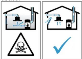
Always ensure adequate fresh air in the room if the appliance is being operated in exhaust air mode at the same time as a room-air-dependent heat-producing appliance is being operated. It is only possible to safely operate the appliance if the pressure in the room in which the heating appliance is installed does not fall below 4 Pa (0.04 mbar). This can be achieved whenever the air needed for combustion is able to enter through openings that cannot be sealed, for example in doors, windows, incoming/exhaust air wall boxes or by other technical means. An incoming/exhaust air wall box alone is not sufficient to ensure compliance with the limit. In any case, consult your responsible chimney sweep. They are able to assess the house's entire ventilation setup and will suggest the suitable ventilation measures to you. Unrestricted operation is possible if the appliance is operated exclusively in circulating-air mode.
WARNING - Risk of fire!
The grease deposits in the grease filter may catch fire.
- Never work with naked flames close to the appliance (e.g. flambéing).
- Do not install the appliance near a heat-producing appliance for solid fuel (e.g. wood or coal) unless a closed, non-removable cover is present. There must be no flying sparks.
WARNING - Risk of injury!
Changes to the electrical or mechanical assembly are dangerous and may lead to malfunctions.
- Do not make any changes to the electrical or mechanical assembly.
Parts that are accessible during installation may have sharp edges and may lead to cutting injuries.
Wear protective gloves. The appliance is heavy. To move the appliance, two people are required. - Use only suitable tools and equipment.
WARNING - Risk of suffocation!
Children may put packaging material over their heads or wrap themselves up in it and suffocate.
- Keep packaging material away from children. Do not let children play with packaging material.
WARNING - Risk of poisoning!
Risk of poisoning from flue gases being drawn back in.
- Do not emit the exhaust air into a smoke or exhaust gas flue that is in operation.
- Do not emit the exhaust air into a shaft that is used to ventilate installation rooms for heat-producing appliances. If the exhaust air is to be conveyed into a smoke or exhaust gas flue, you must obtain the consent of the heating engineer responsible.
Risk of poisoning from flue gases being drawn back in. If an extractor hood with an open-flued heat production source is installed, the power supply for the extractor hood must be provided with a suitable safety switch.
Information about the electrical connection
In order to safely connect the appliance to the electrical system, follow these instructions.
WARNING - Risk of electric shock!
It must always be possible to disconnect the appliance from the electricity supply. The appliance must only be connected to a mains socket that has been installed correctly.
An all-pole isolating switch must be integrated into the permanent electrical installation in accordance with the conditions of overvoltage category III and in accordance with the installation regulations. The permanent electrical installation must only be wired by a professional electrician. We recommend installing a residual-current circuit breaker (RCCB) in the appliance's power supply circuit. - Do not kink or trap the connection cable, and keep it away from sharp edges. - Route the connection cable in such a way that it does not touch the hot casing. - Use only the connection cable that is supplied with the appliance or is provided by technical after-sales service. This appliance complies with the EC interference suppression regulations. - The appliance corresponds to protection class 1. You should therefore only use the appliance with a protective earth connection. The manufacturer shall assume no liability for malfunctions or damage resulting from incorrect electrical wiring.
Preparing the electrical connection
Requirement: Only after-sales service staff who have been trained accordingly may carry out work on the inside of the appliance or replace the power cord.
- Observe the information about the electrical connection. An incorrect installation, an improper installation or connection invalidates the warranty.
- If a longer mains power cable is required, contact the after-sales service. Connecting cables up to 2.20m are available.
- On appliances without a preinstalled cable, insert the power cable into the mains socket.
Opening the mains socket
- Use a screwdriver to lift the cover of the mains outlet.
→Fig. 14
Preparing the mains socket
- Undo the screw. → Fig. 15 2.Use a screwdriver to lift the strain relief. → Fig.16
- Loosen the strain relief. → Fig. 17
Connecting the cable to the mains socket
- For 3N connect the cable to the mains socket in accordance with the following figure. → Fig. 18
- For 2N connect the cable to the mains socket in accordance with the following figure. → Fig. 19
- For 1 N, connect the cable to the mains socket in accordance with the following figure. → Fig.20
- For 2L / 2N connect the cable to the mains socket in accordance with the following figure. → Fig. 21
- Note the colours of the cables.
- BN: Brown
- BU: Blue
- GN/YE: Yellow and green
- BK: Black
- GY: Grey
- If required, install the enclosed copper bridges in accordance with the connection diagram.
- Connect the cables and then tighten the screws of the mains socket.
- For a 1N~ or 2L/2N connection in accordance with the connection diagram, 1 corresponds to the fan motor.
- For a 2N~ / 3N~ connection, phase L1 (grey) corresponds to the fan motor.
Secure the cable in the mains socket
- Use the strain relief to secure the power cable in place.
- Tighten the screw at the correct position.
- Do not use a cordless screwdriver.
→Fig.
- To facilitate closing the mains socket, arrange the cables in the central area of the mains socket.
- Close the cover on the mains socket.
Instructions for the exhaust air pipe
The appliance manufacturer does not provide any warranty for faults attributable to the pipeline.
Use a short, straight exhaust air pipe with as large a pipe diameter as possible. - Long, rough exhaust air pipes, many pipe bends or small pipe diameters reduce the suction power and increase the fan noise. Use an exhaust pipe that is made of non-combustible material. To prevent condensate from returning, fit the exhaust pipe with a 1° gradient from the appliance.
Flat ducts
Use flat ducts with an inner cross-section that corresponds to the diameter of the round pipes:
Diameter of 150 mm corresponds to approx. 177 cm². Use sealing strips for different pipe diameters. - Do not use any flat ducts with sharp bends.
Round pipes
Round pipes with an inner diameter of 150 mm
Instructions for the air extraction mode
For air extraction mode, a one-way flap should be installed.
Notes
If a one-way flap is not included with the appliance, one can be ordered from a specialist retailer. If the exhaust air is conveyed through the external wall, a telescopic duct should be used.
Checking the units
- Check whether the fitted unit is level and has sufficient load-bearing capacity.
The maximum weight of the appliance is approx. 25 kg.
The worktop into which you are fitting the appliance must be able to withstand loads of approx. 60 kg.
- Ensure that the stability of the fitted unit is also guaranteed following cut-out work.
- Use suitable substructures to ensure the load-bearing capacity and stability, particularly in the case of thin worktops.
Take the appliance weight, including additional load, into consideration. - Use heat-resistant and moisture-resistant reinforcement material.
- Ensure that the fitted unit is heat-resistant up to 90 °C.
- Do not support any other appliances, e.g. ovens, refrigerators, dishwashers or washing machines.
- Only check that the appliance is level once it has been installed in the installation opening.
- You can freely select the clearance to a top cabinet. In doing so, take into consideration the ease of use and ergonomics when using the plate.
Flush installation
With the flush installation, the appliance and worktop are on one level. There is no unattractive stepping between the appliance and the worktop.
You can install the appliance in the following temperature-resistant and waterproof worktops:
Stone worktops, plastic worktops (e.g., Corian®), and solid wood worktops.
Installation in compressed-wood worktops is not possible.
Preparing the units
Requirement: The fitted units are heat-resistant up to 90°C.
- Mark the unit cut-out in accordance with the installation diagram. → Fig. 18
- Drill four holes with a diameter of 6 mm → Fig. 23
- Ensure that the angle of the cut surface to the worktop is 90°. → Fig. 28
Observing the minimum clearances when installing above a drawer
- When removing the overflow container on integrated appliances, take the minimum clearances into consideration. → Fig. 10
- Observe the position of the overflow container. → Fig. 11
Attaching adhesive tape
- Attach the supplied long adhesive tape to the edge of the worktop. → Fig. 24
Preparing the unit for circulating-air mode with the adapter
Notes
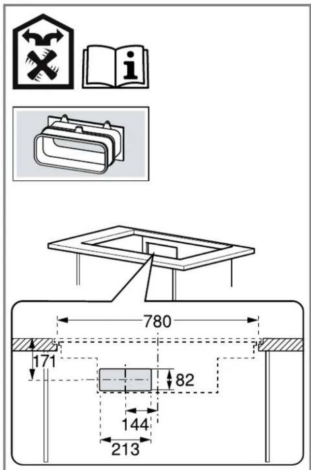
We do not recommend installing on a non-thermally insulated outer wall or above a cold floor (μ ≥ 0.5 W/m²·°C). Air outlets must not be directed at other appliances; they should be separated by a separation panel. If you cannot install separation panels, refer to other installation types. 1. Observe the relevant dimensions when combining with the adapter for the cut-out in the back wall. → Fig. 25 2. Measure the thickness of the worktop. Transfer the measurement to the template and draw a line that corresponds to it. → Fig. 26 3. Cut the template along the marked line for worktop thickness A, the cut centre line B, and the reference line to the inner air outlet C. 4. Mark the centre of the cut-out in the worktop as the centre line on the back panel of the unit. → Fig. 27 5. Align the template to the centre line of the back panel of the unit and to the lower edge of the work surface. 6. Use the template to make the cut-out in the back panel. 7. After making the cut-outs, remove any shavings. 8. Seal the cut surfaces so that they are heat-resistant and waterproof.
→ Fig. 23
Ventilation
- In circulating-air mode, establish an air outlet in the unit's plinth.
- Provide a minimum air outlet cross-section of approx. 400 cm².
- Make the outlet opening in the base panel as large as possible in order to keep draughts and noise to a minimum.
- Make the outlet opening by shortening the plinth or by using suitable ventilation grilles or a lamellar plinth.
→ Fig. 28
- To guarantee that the appliance works correctly, ventilate the hob appropriately via an air outlet with a minimum cross-section of 200 cm² in the base unit.
Note: If the module in which you are installing the appliance has cover panels on the sides, such as islands or worktop ends, you can make an opening on one side or on the rear. Make sure that no furniture or appliances obstruct the airflow.
Installing an appliance featuring circulating-air mode with adapter
Attaching the seal to the adapter
- Attach the seal to the adapter with max. 5 mm to the edge.
See Fig. 29
Attaching the adapter
- Clean and degrease the adhesive surface around the cut-out in the unit's back panel.
- Insert the adapter into the outlet opening on the rear of the hob.
See Fig. 30
- Remove the adhesive tape's protective film from the adapter.
See Fig. 31
Inserting the appliance into the worktop cut-out
- Ensure that the connection cable is connected to the appliance.
- Carefully insert the appliance into the worktop cutout.
See Fig. 32
Screwing the retaining clips in place
- Screw the enclosed retaining clips onto the worktop and carefully onto the appliance.
- Ensure that the hob is at the same height as the worktop and the appliance does not slip.
- Do not use an electric screwdriver.
→ Fig. 33
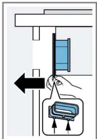
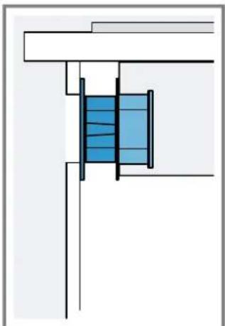
Securing the adapter
- Hold the adapter at the central holder and use the side holders to slide it towards the unit's back panel in the base unit, then affix it.
→ Fig. 34
- If required, also use screws to secure it.
→ Fig. 35
Preparing the unit for circulating-air mode with a circulating-air duct
- If required, remove the unit's back wall.
- Observe the relevant dimensions when combining with the flat duct elbow for the cut-out in the back wall.
- In circulating-air mode, establish an air outlet in the unit's plinth.
- Provide a minimum air outlet cross-section of approx. 400 cm².
- Make the outlet opening in the base panel as large as possible in order to keep draughts and noise to a minimum.
- Make the outlet opening by shortening the plinth or by using suitable ventilation grilles or a lamellar plinth.
- To guarantee that the appliance works correctly, ventilate the hob appropriately via an air outlet with a minimum cross-section of 200 cm² in the base unit.
- After making the cut-outs, remove any shavings.
- Seal the cut surfaces so that they are heat-resistant and waterproof.
Installing the appliance for air recirculation mode with circulating-air duct
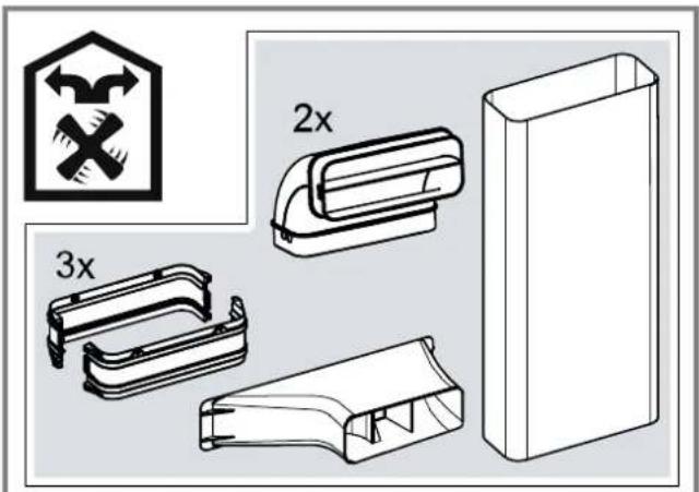
- For circulating-air mode, use the seal, the circulating-air duct, the diffuser and the odour filter.
- Observe the dimensions for the different flat duct bends. → Page 21
Securing the seal
→ Fig. 37
- Secure the enclosed seal on the flat duct elbow at a maximum of 5 mm from the edge.
Inserting the flat duct elbow
- Insert the flat duct elbow into the outlet opening on the rear of the appliance.
→ Fig. 38
Inserting the appliance into the worktop cut-out
- Ensure that the connection cable is connected to the appliance.
- Carefully insert the appliance into the worktop cutout.
→ Fig. 39
Establishing the pipework between the appliance and the diffuser
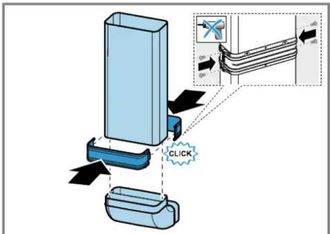
- Connect the components of the circulating-air duct to each other.
- Secure the flat duct pipe connector by engaging it in place.
- For an additional fixing, screw the flat duct pipe connector together using 4 x PT 4 x 8 mm screws for plastic.
→ Fig. 40
- Connect the circulating-air duct to the flat duct elbow on the rear of the hob. → Fig. 41
- Connect the diffuser to the circulating-air duct. → Fig. 49
Screwing the retaining clips in place
- Screw the enclosed retaining clips onto the worktop and carefully onto the appliance.
- Ensure that the hob is at the same height as the worktop and the appliance does not slip.
- Do not use an electric screwdriver. → Fig. 48
Preparing the unit for air extraction mode
- If required, remove the unit's back wall.
- Observe the relevant dimensions when combining with a flat duct elbow for the cut-out in the back wall.
→ Fig. 44
- After making the cut-outs, remove any shavings.
- Seal the cut surfaces so that they are heat-resistant and waterproof.
→ Fig. 45
Install the appliance for air extraction mode
- For air extraction mode, use the seal and the acoustics filters.
- Observe the instructions for the exhaust air pipe. → Page 23
Securing the seal
- Secure the enclosed seal on the flat duct elbow at a maximum of 5 mm from the edge. → Fig. 37
Establishing the piping
- Insert the flat duct elbow into the outlet opening on the rear of the appliance. → Fig. 38
- If required, install additional piping elements.
Inserting the appliance into the worktop cut-out
- Ensure that the connection cable is connected to the appliance.
- Carefully insert the appliance into the worktop cutout.
→ Fig. 39
Screwing the retaining clips in place
- Screw the enclosed retaining clips onto the worktop and carefully onto the appliance.
- Ensure that the hob is at the same height as the worktop and the appliance does not slip.
- Do not use an electric screwdriver. → Fig. 33
Connecting the exhaust air pipe
- Secure the exhaust air pipe to the flat duct bend.
- Establish the connection to the exhaust air opening.
- Seal the joints appropriately.
Inserting filters
Note: For circulating-air mode, insert the odour filters.
For air extraction mode, insert the acoustics filters.
- Observe the filters' air flow direction.
- Insert two of the filters into the left and right of the appliance, and slide them forwards.
→ Fig. 46
- Insert the other filters into the left and right of the appliance. → Fig. 27
Inserting grease filters
- Insert the grease filter. →Fig.4
Establishing the connection to the power supply
- Observe the connection data on the rating plate.
- For 3N, connect the cable to the mains socket in accordance with the figure.
→Fig.49
- For 2N, connect the cable to the mains socket in accordance with the figure. → Fig. 50
- For 1N, connect the cable to the mains socket in accordance with the figure. → Fig. 51
- For 2L/2N, connect the cable to the mains socket in accordance with the figure. →Fig.52
- Note the colours of the cables.
- BN: Brown
- BU: Blue
- GN/YE: Yellow and green
- BK: Black
- GY: Grey
- If required, arrange the supplied wire end ferrules differently depending on the type of connection.
- To connect two cables, if required, use a wire end ferrule.
- Shorten the wires.
- Remove the insulation.
Checking the function
- Switch on the appliance.
- If the appliance is not connected correctly. → "Checking and correcting the electrical connection", Page 25
- If no faults appear in the appliance's display, use the operating instructions to check that the ventilation is working.
Checking and correcting the electrical connection
- Disconnect the appliance from the power supply.
- Check whether the connection to the appliance and the building-side connection correspond to the connection diagram in these installation instructions. → "Preparing the electrical connection", Page 22 → "Establishing the connection to the power supply", Page 25
3. For 3N, observe the following figure. → Fig. 53 4. For 2N, observe the following figure. → Fig. 54 5. For 1N, observe the following figure. → Fig. 55
Sealing crevices
Requirement: You must carry out a function test before sealing any joints.
- Protect the glass surface by applying residue-free adhesive tape along the edge. → Fig. 56
- Seal all around the gap using suitable, heat-resistant silicone, e.g. Novasil® S70 or Ottoseal® S70. → Fig. 57
Use matte silicone for matte surfaces.
Using unsuitable silicone adhesive on natural stone work surfaces may cause permanent discolouration.
- Use the smoothing agent recommended by the manufacturer to smooth the joint.
- Observe the usage instructions for the silicone adhesive.
- Leave the silicone adhesive to dry for at least 24 hours.
The drying time depends on the ambient temperature.
- Do not operate the appliance until the silicone has dried completely.
Switching the display for air extraction mode
- If required for the air extraction mode and the air recirculation mode, change the display of the electronic control in the basic settings.
- Observe the basic settings section in the instruction manual.
Removing the appliance
ATTENTION!
Tools may damage the appliance frame. Do not pry the appliance out from above. 1. Disconnect the appliance from the power supply. 2. Remove the exhaust air duct or undo the circulating-air connections. 3. Remove the silicone joint. 4. Push out the appliance from below.
Position of overflow reservoir:
→Fig.11
WARNING - Risk of fire!
WARNING - Fire hazard!
WARNING - Risk of fire!
Fastening the ceiling
- Fasten the supplied ceiling to the flat duct bend max. 5 mm from the edge.
→Fig.37
Fastening the ceiling
Mounting template for flat duct bend
Here you will find an overview of the mounting templates for flat duct bends.
Side view:
→ Fig. 4, → Fig. 5, → Fig. 6
Front view:
→ Fig. 7
Distance to overlap container:
Fig. 10
WARNING - Risk of injury!
WARNING - Risk of injury!
Inserting the flat duct bend
- Insert the flat duct bend into the outlet on the back of the appliance. → Fig. 38
Inserting the appliance into the cutout in the worktop
- Make sure that the connection cable is connected to the appliance.
- Carefully insert the appliance into the cutout in the worktop.
→Fig. 39
Prepared frame for evacuation
→Fig. 44
Mounting dimensions for flat air duct
Here are the dimensions of the device →PNC 31. Here is a selection of mounting dimensions for the flat air duct. Side view: →PNC. →PNC. →PNC. Top view: →PNC.
Installation options
Here is an overview of the various installation options.
Filter for air purification and maintenance:
→PNC. 3
Seals and gaskets for air outlet:
→PNC. 9
Note: The air ducts for installation can be purchased from the service department, or from specialized retailers.
Safety distances
Observe the safety distances for your device.
Distance to the tank for the liquid level sensor:
→PUC.10
Positioning the container for the liquid:
→PUC.
Optimal power is achieved if the distance between the rear wall of the hood and the wall is 50 mm. If the distance is insufficient, the power decreases.
→PUC.12
Maintain safe distances when making a cutout in the countertop.
Do not place objects in the extraction hood whose height exceeds the maximum height of the hood. Such objects may fall into the main appliance, thereby interfering with its operation.
→PUC.18

General instructions
Read this manual carefully. Only a qualified specialist may connect the appliance. Before carrying out any work, disconnect the power supply. It is forbidden to use the appliance on boats or in cars. Follow the recommendations of the countertop manufacturer.
Safety during installation
When installing the appliance, follow the given safety instructions.
Safe operation is guaranteed only with qualified installation in compliance with the installation instructions. The installer is responsible for the correctness of the installation.
Note: This appliance is designed to extract vapors from cooking in a pot placed on the cooking zone. If the appliance is used with other appliances (for example, cooktops or frying pans), the effectiveness of the ventilation system will depend on the distance between the air intake and the point of vapor emission.
WARNING - Danger: Magnetism!
The appliance contains permanent magnets. They may affect implanted electronic devices, such as pacemakers or insulin pumps.
- Persons with electronic implants must not approach the appliance closer than 10 cm.
WARNING - Risk of poisoning!
Flue gases can cause poisoning. Heaters that draw combustion air from the room (e.g., gas, oil, wood, or coal heaters, instantaneous water heaters, cookers) obtain the air for combustion from the room where they are installed, and the flue gases are discharged through a ventilation system (e.g., a flue pipe) from the room to the outside. During operation, the ventilation removes air from the kitchen and adjacent rooms. Without sufficient supply of atmospheric air in the room, the pressure may drop, and toxic gases from the flue or ventilation may be drawn back into the living space.
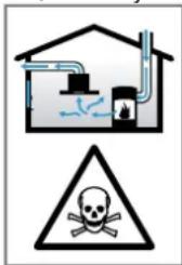
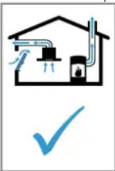
Always ensure a sufficient supply of air if the appliance is a heater with a supply of air from the room and the ventilation systems operate simultaneously in the air extraction mode. A safe operating condition for the appliance with an open flue is a pressure drop of no more than 4 Pa (0.04 mbar). This can be achieved if the required combustion air can flow through non-closable openings, for example, in doors, windows, with the help of a wall-mounted supply/exhaust air box or other technical measures. A single supply/exhaust air box does not guarantee compliance with the limit value. In any case, consult a competent person responsible for the operation of the flue system, capable of ventilating the entire house, and ask them to propose a solution for taking appropriate measures. If the appliance operates exclusively in the air circulation mode, operation is possible without restrictions.
WARNING - Risk of fire
Grease deposits in the grease filter may catch fire. Never work with an open flame near the appliance (e.g., flambéing). The appliance may be installed near a solid fuel heating source (e.g., wood or coal), if a non-flammable protective plate is provided. There must be no flying sparks.
WARNING - Risk of injury!
Modification of the mechanical or electrical construction may become a source of danger and lead to the appliance going out of order.
- Modification of the mechanical or electrical construction is prohibited. Parts opened during installation may be sharp and can cause cuts.
- Wear protective gloves. The appliance is heavy. Moving it requires two people. Use only suitable auxiliary means.
WARNING - Risk of suffocation!
Packaging material can be dangerous for children. Never allow children to play with packaging material.
Do not allow children to play with packaging material. Do not let children play with the packaging material.
WARNING - Risk of poisoning!
Exhaust gases that have been treated may become toxic.
The exhaust air must not be discharged through the flue or air duct during their operation. For the supply of combustion air, use only the ventilation ducts intended for ventilation of the room where the appliance is installed. Before connecting the appliance to the flue, it is necessary to obtain permission from the relevant authority responsible for the operation and cleaning of the flue.
Exhaust gases that have been treated may become toxic. When installing the appliance in rooms where there is a source of flame with air supply from the room, the air supply system must be equipped with a safety shutdown function.
Instructions for connection to the electrical network
For safe connection of the appliance to the electrical network, follow the instructions below.
DANGER - Risk of electric shock!
It must be possible to disconnect the appliance from the electrical network at any time. This appliance may be connected to the wall only through a properly installed distribution box.
In the fixed electrical installation, a special switch must be provided for disconnecting all poles, in accordance with the overvoltage category conditions and installation conditions. Connection of the fixed electrical equipment must be carried out only by a qualified electrician. We recommend installing a residual current device (RCD) in the electrical supply circuit of the appliance. Make sure that the power cable is not pinched and that it is kept away from sharp edges. - Route the power cable so that it does not come into contact with the hot parts of the appliance. Use only the power cable supplied with the appliance or supplied by the after-sales service. This appliance complies with the EC regulations on radio interference. The appliance complies with Class I, so it must be operated only with an earth connection. The manufacturer is not responsible for malfunctions or possible damage that may be caused by incorrect electrical installation.
Preparation for electrical connection
Requirement: Work on the internal parts of the appliance or replacement of the power cable may only be carried out by trained service technicians.
- Follow the instructions for connection to the electrical network. In case of incorrect assembly, installation, or connection that does not comply with the instructions, the appliance warranty becomes void.
- If you need a longer power cable, contact the after-sales service. We have cables up to 2.20 m long.
- When installing the appliance without a pre-installed cable, route the power cable to the distribution box.
Opening the distribution box
Open the cover of the distribution box using a screwdriver.
→ Fig. 14
Wiring of the junction box
→ Fig. 15
→ Fig. 16
→ Fig. 17
- 1. Loosen the screw. 2. Insert the cable gland with a screwdriver. 3. Loosen the cable gland fixation.
Connecting the cable to the junction box
1. Connect terminal 3N of the cable to the junction box, as shown in the following figure. → Fig. 18 2. Connect terminal 2N of the cable to the junction box, as shown in the following figure. → Fig. 19 3. Connect terminal 1N of the cable to the junction box, as shown in the following figure. → Fig. 20 4. Connect terminal 2L/2N of the cable to the junction box, as shown in the following figure. → Fig. 21
- Observe the color of the cables.
- BN: brown - BU: blue - GN/YE: green/yellow - BK: black - GY: gray
- If necessary, install the supplied jumpers according to the connection diagram. 7. Connect the cables, then tighten the screws on the junction box.
- According to the connection diagram, connection 1N~ corresponds to phase 1 of the fan motor. 9. Connection 2N~/3N~ corresponds to phase L1 (gray) of the fan motor.
Use a short, straight exhaust duct with the largest possible diameter. Long, rough exhaust ducts, many elbows, or small diameter ducts reduce exhaust power and increase noise from the fan. Use exhaust ducts made of non-flammable materials. To prevent backflow, install the exhaust duct at an angle of 1° to the appliance.
Flat ducts
Use flat ducts whose internal cross-section corresponds to the diameter of round pipes:
The duct diameter of 150 mm corresponds to approx. 177 cm². If the pipe diameters do not match, use a sealing collar. Do not use flat ducts with sharp bends.
Round ducts
The recommended internal diameter for round ducts is 150 mm.
Instructions for the air exhaust duct
A non-return flap must be installed in the air exhaust duct.
Notes
If the non-return flap is not included in the appliance's delivery, it can be purchased from a specialized store. If the exhaust air is discharged through an external wall, use a telescopic ventilation duct passing through the wall.
Checking the furniture
- Make sure that the furniture or the built-in installation is level and can support the load. The maximum weight of the appliance is approx. 25 kg. The worktop into which the appliance is built must support a load of approx. 60 kg.
- After making the cutout, check the stability of the furniture for the built-in installation.
- Ensure the load-bearing capacity and stability with suitable supporting structures, especially for thin worktops.
- Take into account the weight of the appliance, including any additional load.
- Use moisture-resistant materials.
- Make sure that the furniture or the built-in unit can withstand temperatures up to 90°C. Do not install built-in ovens, refrigerators, dishwashers, washing machines, or other appliances under the appliance.
- The correct positioning of the wires in the horizontal plane must be checked after installation in the mounting recess.
- The distance to the wall-mounted cabinet can be chosen at your discretion. When using the appliance, take into account comfort and ergonomics.
Built-in installation
When installing the built-in appliance, it must be at the same level as the countertop. There must be no interfering elements between the appliance and the countertop. The appliance can be installed in the following heat-resistant and waterproof countertops:
Stone countertops, countertops made of synthetic materials (e.g., Corian®), solid wood countertops
Installation in countertops made of pressed wood is not possible.
Furniture preparation
Requirement: The furniture for built-in installation must withstand temperatures up to 90°C.
- Mark the cutout location in the furniture according to the installation diagram.
Drill four holes with a diameter of 6 mm.
- Make sure that the cutting angle relative to the countertop surface is 90°.
When installing above the hob, maintain minimum clearances.
- When installing the appliance above the hob, maintain minimum clearances on the installed appliance.
→ PHC. 10
2. Consider the position of the appliance above the hob or the hob.
→ PNC.
Attaching the adhesive tape
Attach the supplied adhesive tape to the inner top of the cutout in the worktop.
→ PUC. 24
Preparing the furniture for installing the appliance for air circulation with adapter
Notes
Installation on an external wall without thermal insulation or on a non-insulated floor is not recommended (µ ≥ 0.5W/m2). Do not connect the side to the exhaust directly to other appliances without partitions. If it is impossible to install partitions, see "Other installation methods".
1. When combined with an adapter, consider the correspondence of the cutout dimensions in the rear wall.
→ PHC. 25
2. Measure the thickness of the worktop. Transfer the measurement to the template and draw the corresponding line.
- Align the template on the layout for the thickness of the tabletop A, the central line of the cutout B, and the control line for the inner exhaust opening C.
- Mark the center of the cutout B on the tabletop center line on the rear wall of the cabinet.
- Align the template along the center line on the rear wall of the cabinet and along its lower edge with the tabletop.
- Make the cutout in the rear wall according to the template.
- After making the cutout, remove any burrs.
- Seal the joints of the thermostats and the waterproofing with a sealing compound.
Ventilation
1. Install the air valve in the window or the air supply grille.
The minimum cross-section of the opening must be 400 cm2. The exhaust opening in the window pane must be large enough to reduce the power of the fan and ensure a low noise level. Make the exhaust opening by shortening the window panes, using appropriate ventilation grilles or a plinth.
- For the appliance to function correctly, ensure air supply to the vapor chamber through the air outlet opening with a minimum cross-section of 200 cm² in the lower cabinet.
Note: If the cabinet in which the appliance is installed has closed sides, for example, in the case of islands or end panels, the opening can be made on one side or at the rear. Make sure that furniture or appliances do not obstruct the airflow.
Installing the appliance with air recirculation mode with adapter and sealing gasket on the adapter
Attach the sealing gasket to the adapter at a distance of no more than 5 mm from the edge.
→Fig. 29
Installing the adapter
- Clean and degrease the mounting surface around the cutout in the rear wall of the furniture. 2. Install the adapter into the exhaust opening in the rear part of the vapor chamber.
→Fig. 30
- Remove the protective film from the adapter. →Fig. 31
Installing the appliance into the cutout in the countertop
- Make sure that the power cord is connected to the appliance. 2. Carefully install the appliance into the countertop cutout.
→Fig. 32
Tightening the clamps
Install the clamps from the accessory kit onto the countertop and carefully screw them to the appliance. Ensure that the vapor chamber is at the same height as the countertop and that the appliance does not move. Do not use a power drill. →Fig. 33
Adapter fixation
1. Remove the protective caps from the filter, connect it with the side brackets to the rear wall in the lower and upper parts, and secure it. → Fig. R4 2. If necessary, additionally secure the filter with screws. → Fig. 35
Preparing the furniture for installing the device for air circulation with a circulation channel
1. If necessary, remove the back panel of the furniture. 2. When combining a flat channel with a duct, match the dimensions of the cutout in the rear wall.
→ Fig. 361
3. Install the air valve in the location for air circulation.
The minimum cross-section of the air valve must be approx. 400 cm². The exhaust opening in the plinth must be large enough to reduce the power of the fan and ensure a low noise level. Make the exhaust opening by shortening the plinth rails or use appropriate ventilation grilles for the plinth.
- For the device to function correctly, ensure air supply to the vapor barrier through the opening for air outlet with a minimum cross-section of 200 cm² in the lower cabinet.
- After making the cutout, remove the shavings.
- Seal the joints with heat-resistant and waterproof sealant.
→ Fig. 23
Installation of the device for operation in air circulation mode with a circulation channel
- Use the seal, circulation channel, HEPA filter, and activated carbon filter for air recirculation.
- Consider the dimensions of the various flat air ducts. → Page 81
Fixing the device
Secure the inlet included in the delivery set with the seal on the flat channel no more than 5 mm from the edge. → Fig. 37
Installation of the flat duct
Install the flat duct into the outlet opening on the rear wall of the device. → Fig. 38
Installing the device into the cutout in the tabletop
- Make sure that the power cord is connected to the device. 2. Carefully install the device into the cutout in the tabletop.
→ Fig. 39
Installation of the pipe system between the device and the diffuser
- Connect the components of the circulation duct to each other.
- Secure the flat duct connectors by fixing them with a clamp. For more reliable fixation, screw the flat duct connectors with 4 screws for plastic plates PT 4x8 mm.
→ Fig. 40
- Connect the circulation duct to the flat air duct to the rear part of the hob version. → Fig. 41 3. Connect the diffuser to the circulation duct. → Fig. 42
Tightening the clamps
Install the clamps from the delivery set on the tabletop, carefully screwing them to the device.
Make sure that the hob version is at the same height as the tabletop, and the device does not shift.
Do not use an electric drill.
→Fig. 43
Preparing the furniture for installation in air extraction mode
- If necessary, remove the rear wall of the furniture. 2. When combined with a flat duct, check the dimensions of the cutout in the rear wall.
→Fig. 44
- After making the cutout, remove the shavings.
- Seal the joints with heat-resistant and waterproof sealant.
→Fig. 45
Installing the appliance for operation in air extraction mode
- In air extraction mode, use the sealing gaskets and the supplied filters. 2. Follow the instructions for operation in air extraction mode. → Page 83
Fixing the appliance
Secure the sealing gaskets supplied with the appliance on the flat duct, no more than 5 mm from the edge. →Fig. 37
Installation of the duct system
- Install the flat duct into the exhaust opening on the rear wall of the appliance.
→Fig. 38
2. If necessary, install additional elements of the pipe system.
Installing the device in a cutout in the countertop
→ Fig. 39
- Make sure that the power cable is connected to the device. 2. Carefully install the device in the cutout of the countertop.
Tightening the clamps
→ Fig. 33
Install the clamps from the delivery kit on the countertop, carefully screwing them to the device. Then make sure that the device is at the correct height relative to the countertop and does not move. Do not use a power screwdriver.
Connecting the exhaust pipe
- Attach the exhaust pipe to the elbow of the flat air duct.
- Make the connection with the exhaust opening.
- Re-tighten the connection points accordingly.
Installing filters
Before commissioning, install the filters that absorb odors.
Before air outlet, install sound-absorbing filters.
- Pay attention to the direction of the air flow of the filters. 2. Insert the two filters into the device, left and right, and push them forward.
→ P_HC. 46
→ P_HC. 47
- Insert the other two filters into the device, left and right.
Installation of the inlet filter
Install the inlet filter. → P_HC 48
Electrical connection
- Consider the connection parameters in the table. 2. Connect terminal 3N cable to the distribution box, as shown in the figure.
→ P_HC. 49
3. Connect terminal 2N cable to the distribution box, as shown in the figure.
→ P_HC. 50
4. Connect terminal 1N cable to the distribution box, as shown in the figure.
→ P_HC. 51
5. Connect terminal 2L/2N cable to the distribution box, as shown in the figure.
→ P_HC. 52
- Consider the color of the cables.
- Depending on the type of connection, if necessary, position the cable clamps supplied in the kit differently.
- If necessary, use the cable clamps to connect two cables.
- Shorten the cable ends.
- Remove the insulation.
Checking operation
- Switch on the device.
- If the LED lights up or blinks incorrectly, see "Checking and adjusting the connection to the electrical network", page 86.
- If no error indication appears on the device display, check the ventilation operation, following the operating instructions.
Checking and adjusting the connection to the electrical network
- Disconnect the device from the mains. 2. Make sure that the connection on the device and the connection on the wall correspond to the connection diagram in the installation instructions. → "Preparation for electrical connection", page 83 → "Electrical connection", page 86 3. Pay attention to the following figure. →Fig. 53 4. Pay attention to the following figure. → Fig. 54 5. Pay attention to the following figure. →Fig. 55
Sealing the joints
Requirement: Before sealing the joints, you must check the functioning of the device.
- Protect the glass surface by applying a silicone adhesive that leaves no residue along its edge. →Fig. 56
- Seal the gap around the perimeter with a suitable silicone sealant, for example, Novasil® S70 or Ottoseal® S70.
→Fig. 57
For matte surfaces, use a matte silicone sealant.
Using an unsuitable silicone adhesive on natural stone worktops may change the color in some places.
- Polish the joints with the recommended product. 4. Strictly follow the instructions for using the silicone adhesive. 5. Allow the silicone adhesive to dry for at least 24 hours.
The drying time depends on the ambient temperature.
- Operation of the device is only permitted after the silicone has completely dried.
Presetting the air extraction mode
- If necessary, adjust the electronic control of the basic settings for the air extraction mode accordingly.
- See the chapter "Basic settings" in the operating instructions.
Dismantling the device
When using tools, you can damage the instrument frame.
Do not pull the device out from above. 1. Disconnect the device from the power supply.
2. Remove the drain hose or loosen the connection for air circulation. 3. Cut the silicone seam. 4. Extract the device by pushing it from below.
- QR CODE FOR THE INSTALLATION VIDEO
- APPLIANCE DIMENSIONS
- INSTALLATION DIMENSIONS FOR FLAT DUCT BENDS
- INSTALLATION VARIANTS
- ODOUR FILTER AND ADAPTER FOR CIRCULATING-AIR MODE
- ACOUSTICS FILTER AND SEAL FOR AIR EXTRACTION MODE: → FIG
- SAFETY CLEARANCES
- GENERAL INFORMATION
- SAFE INSTALLATION
- WARNING - DANGER: MAGNETISM
- WARNING - RISK OF POISONING
- WARNING - RISK OF FIRE
- WARNING - RISK OF INJURY
- WARNING - RISK OF SUFFOCATION
- INFORMATION ABOUT THE ELECTRICAL CONNECTION
- WARNING - RISK OF ELECTRIC SHOCK
- PREPARING THE ELECTRICAL CONNECTION
- OPENING THE MAINS SOCKET
- PREPARING THE MAINS SOCKET
- CONNECTING THE CABLE TO THE MAINS SOCKET
- SECURE THE CABLE IN THE MAINS SOCKET
- INSTRUCTIONS FOR THE EXHAUST AIR PIPE
- FLAT DUCTS
- ROUND PIPES
- INSTRUCTIONS FOR THE AIR EXTRACTION MODE
- NOTES
- CHECKING THE UNITS
- FLUSH INSTALLATION
- PREPARING THE UNITS
- OBSERVING THE MINIMUM CLEARANCES WHEN INSTALLING ABOVE A DRAWER
- ATTACHING ADHESIVE TAPE
- PREPARING THE UNIT FOR CIRCULATING-AIR MODE WITH THE ADAPTER
- VENTILATION
- INSTALLING AN APPLIANCE FEATURING CIRCULATING-AIR MODE WITH ADAPTER
- ATTACHING THE SEAL TO THE ADAPTER
- ATTACHING THE ADAPTER
- INSERTING THE APPLIANCE INTO THE WORKTOP CUT-OUT
- SCREWING THE RETAINING CLIPS IN PLACE
- SECURING THE ADAPTER
- PREPARING THE UNIT FOR CIRCULATING-AIR MODE WITH A CIRCULATING-AIR DUCT
- INSTALLING THE APPLIANCE FOR AIR RECIRCULATION MODE WITH CIRCULATING-AIR DUCT
- SECURING THE SEAL
- INSERTING THE FLAT DUCT ELBOW
- ESTABLISHING THE PIPEWORK BETWEEN THE APPLIANCE AND THE DIFFUSER
- PREPARING THE UNIT FOR AIR EXTRACTION MODE
- INSTALL THE APPLIANCE FOR AIR EXTRACTION MODE
- ESTABLISHING THE PIPING
- CONNECTING THE EXHAUST AIR PIPE
- INSERTING FILTERS
- INSERTING GREASE FILTERS
- ESTABLISHING THE CONNECTION TO THE POWER SUPPLY
- CHECKING THE FUNCTION
- CHECKING AND CORRECTING THE ELECTRICAL CONNECTION
- SEALING CREVICES
- SWITCHING THE DISPLAY FOR AIR EXTRACTION MODE
- REMOVING THE APPLIANCE
- ATTENTION
- WARNING - FIRE HAZARD
- FASTENING THE CEILING
- MOUNTING TEMPLATE FOR FLAT DUCT BEND
- INSERTING THE FLAT DUCT BEND
- INSERTING THE APPLIANCE INTO THE CUTOUT IN THE WORKTOP
- PREPARED FRAME FOR EVACUATION
- MOUNTING DIMENSIONS FOR FLAT AIR DUCT
- INSTALLATION OPTIONS
- SAFETY DISTANCES
- GENERAL INSTRUCTIONS
- SAFETY DURING INSTALLATION
- INSTRUCTIONS FOR CONNECTION TO THE ELECTRICAL NETWORK
- DANGER - RISK OF ELECTRIC SHOCK
- PREPARATION FOR ELECTRICAL CONNECTION
- OPENING THE DISTRIBUTION BOX
- WIRING OF THE JUNCTION BOX
- CONNECTING THE CABLE TO THE JUNCTION BOX
- ROUND DUCTS
- INSTRUCTIONS FOR THE AIR EXHAUST DUCT
- CHECKING THE FURNITURE
- BUILT-IN INSTALLATION
- FURNITURE PREPARATION
- WHEN INSTALLING ABOVE THE HOB, MAINTAIN MINIMUM CLEARANCES
- ATTACHING THE ADHESIVE TAPE
- PREPARING THE FURNITURE FOR INSTALLING THE APPLIANCE FOR AIR CIRCULATION WITH ADAPTER
- INSTALLING THE APPLIANCE WITH AIR RECIRCULATION MODE WITH ADAPTER AND SEALING GASKET ON THE ADAPTER
- INSTALLING THE ADAPTER
- INSTALLING THE APPLIANCE INTO THE CUTOUT IN THE COUNTERTOP
- TIGHTENING THE CLAMPS
- ADAPTER FIXATION
- PREPARING THE FURNITURE FOR INSTALLING THE DEVICE FOR AIR CIRCULATION WITH A CIRCULATION CHANNEL
- INSTALLATION OF THE DEVICE FOR OPERATION IN AIR CIRCULATION MODE WITH A CIRCULATION CHANNEL
- FIXING THE DEVICE
- INSTALLATION OF THE FLAT DUCT
- INSTALLING THE DEVICE INTO THE CUTOUT IN THE TABLETOP
- INSTALLATION OF THE PIPE SYSTEM BETWEEN THE DEVICE AND THE DIFFUSER
- PREPARING THE FURNITURE FOR INSTALLATION IN AIR EXTRACTION MODE
- INSTALLING THE APPLIANCE FOR OPERATION IN AIR EXTRACTION MODE
- FIXING THE APPLIANCE
- INSTALLATION OF THE DUCT SYSTEM
- INSTALLING THE DEVICE IN A CUTOUT IN THE COUNTERTOP
- CONNECTING THE EXHAUST PIPE
- INSTALLING FILTERS
- INSTALLATION OF THE INLET FILTER
- ELECTRICAL CONNECTION
- CHECKING OPERATION
- CHECKING AND ADJUSTING THE CONNECTION TO THE ELECTRICAL NETWORK
- SEALING THE JOINTS
- PRESETTING THE AIR EXTRACTION MODE
- DISMANTLING THE DEVICE
Brand : NEFF
Model : V68PHL4B0
Category : Cooker