CWM P - Electric heater STIEBEL ELTRON - Free user manual and instructions
Find the device manual for free CWM P STIEBEL ELTRON in PDF.

| Product type | Wall-mounted electric convector |
| Brand | Stiebel Eltron |
| Model | CWM P |
| Rated power output | 500 W, 750 W, 1000 W, 1500 W, 2000 W, 2500 W, 3000 W depending on version |
| Electrical supply | 1/N/PE ~230 V, 50 Hz |
| Dimensions (H × W × D) | 450 × 348-1050 × 100 mm depending on version |
| Weight | 4.0 to 10.9 kg depending on version |
| Protection rating | IP24 |
| Protection class | I |
| Temperature control | Electronic with weekly programmer |
| Main functions | Comfort mode, reduced mode, frost protection (7 °C), open window detection, adaptive start |
| Display and controls | Digital backlit display, touch keys, child lock |
| Installation | Wall-mounted, bracket supplied, minimum distances to be observed, connection to mains plug or fixed |
| Maintenance and cleaning | Clean with a damp cloth after cooling, do not use spray or abrasive products |
| Safety | Do not cover, keep children away, safety limiter in case of overheating |
| Spare parts and repairability | Original parts only by approved installer; professional maintenance recommended after 10 years |
| Warranty | Warranty according to conditions of the country of distribution |
| General information | Compliant with ErP directive 2015/1188, color alpine white |
Frequently Asked Questions - CWM P STIEBEL ELTRON
User questions about CWM P STIEBEL ELTRON
0 question about this device. Answer the ones you know or ask your own.
Ask a new question about this device
Download the instructions for your Electric heater in PDF format for free! Find your manual CWM P - STIEBEL ELTRON and take your electronic device back in hand. On this page are published all the documents necessary for the use of your device. CWM P by STIEBEL ELTRON.
USER MANUAL CWM P STIEBEL ELTRON
OPERATION AND INSTALLATION UTILISATION ET INSTALLATION BEDIENING EN INSTALLATIE OBSLUHA A INSTALACE OBSLUHA A INSTALÁCIA OBSŁUGA I INSTALACJA KEZELÉS ÉS TELEPÍTÉS COMANDĂ ȘI INSTALARE
Wall mounted convector heater | Convecteur mural | Wandconvector | Nástěnný konvektor | Nástenný konvektor | Konwektor wiszący | Fali konvektor | Convector de perete
» CWM 500 P
» CWM 750 P
» CWM 1000 P
» CWM 1500 P
» CWM 2000 P
» CWM 2500 P
» CWM 3000 P
» CWM 500 U
» CWM 750 U
» CWM 1000 U
» CWM 1500 U
» CWM 2000 U
» CWM 2500 U
» CWM 3000 U
natural_image
Line drawing of a rectangular electronic device with ventilation grilles and a control panel (no text or symbols)SPECIAL INFORMATION
OPERATION
- General information 3
1.1 Safety instructions 3
1.2 Other symbols in this documentation ____ 3
1.3 Information on the appliance 3
1.4 Units of measurement 3
- Safety 3
2.1 Intended use 3
2.2 General safety instructions 4
2.3 Test symbols 4
-
Appliance description 4
-
Operation 4
4.1 Programming unit 5
4.2 Switching the appliance on and off 5
4.3 Standby mode 5
- Settings 6
5.1 Standard display 6
5.2 Standard menu 6
5.3 Configuration menu 6
-
Cleaning, care and maintenance 8
-
Troubleshooting 8
INSTALLATION
- Safety 8
8.1 General safety instructions 8
8.2 Instructions, standards and regulations ____ 8
- Appliance description 9
9.1 Standard delivery 9
- Installation 9
10.1 Installation site 9
10.2 Minimum clearances 9
10.3 Installing the wall mounting bracket 9
10.4 Appliance installation 10
10.5 Removing the appliance 10
10.6 Electrical connection 10
-
Commissioning 11
-
Troubleshooting 11
-
Appliance handover 11
-
Specification 12
14.1 Dimensions and connections 12
14.2 Energy consumption data 12
14.3 Data table 13
GUARANTEE
ENVIRONMENT AND RECYCLING
SPECIAL INFORMATION
- Keep children under the age of 3 away from the appliance if constant supervision cannot be guaranteed.
- Children from the age of 3 to 7 may switch the appliance on and off, provided they are supervised or have been instructed in the safe operation of the appliance and understand any risks that may result. This is subject to the appliance having been installed as described. Children from the age of 3 to 7 must not plug the power cable into its socket or regulate the appliance.
- The appliance may be used by children aged 8 and older and persons with reduced physical, sensory or mental capabilities or a lack of experience and know-how, provided that they are supervised or they have been instructed on how to use the appliance safely and have understood the potential risks.
- Children must never play with the appliance. Children must never clean the appliance or perform user maintenance unless they are supervised.
- Parts of the appliance can get very hot and may cause burns. Particular caution is advised when children or vulnerable persons are present.
- In order to avoid overheating, do not cover the heater.
- Never install the appliance directly below a wall socket.
- In the case of a permanent connection, the appliance must be able to be separated from the power supply by an isolator that disconnects all poles with at least 3 mm contact separation.
- The power cable must only be replaced (for example if damaged) by a qualified contractor authorised by the manufacturer, using an original spare part.
- Secure the appliance as described in chapter "Installation / Installation".
OPERATION
1. General information
The chapters "Special information" and "Operation" are intended for both users and qualified contractors.
The chapter "Installation" is intended for qualified contractors.

Note
Read these instructions carefully before using the appliance and retain them for future reference.
Pass on the instructions to a new user if required.
1.1 Safety instructions
1.1.1 Structure of safety instructions

KEYWORD Type of risk
Here, possible consequences are listed that may result from failure to observe the safety instructions.
▶ Steps to prevent the risk are listed.
1.1.2 Symbols, type of risk
Symbol Type of risk

Injury

Electrocution

Burns
(burns, scalding)
1.1.3 Keywords
KEYWORD Meaning
| DANGER | Failure to observe this information will result in serious injury or death. |
| WARNING | Failure to observe this information may result in serious injury or death. |
| CAUTION | Failure to observe this information may result in non-serious or minor injury. |
1.2 Other symbols in this documentation

Note
General information is identified by the adjacent symbol.
▶ Read these texts carefully.
Symbol Meaning

Material losses
(appliance damage, consequential losses and environmental pollution)
Appliance disposal

This symbol indicates that you have to do something. The action you need to take is described step by step.
1.3 Information on the appliance
Symbol Meaning

Never cover the appliance
1.4 Units of measurement

Note
All measurements are given in mm unless stated otherwise.
2. Safety
2.1 Intended use
This appliance is designed to heat living areas.
The appliance is intended for domestic use. It can be used safely by untrained persons. The appliance can also be used in a non-domestic environment, e.g. in a small business, as long as it is used in the same way.
Any other use beyond that described shall be deemed inappropriate. Observation of these instructions and of the instructions for any accessories used is also part of the correct use of this appliance.
2.2 General safety instructions

WARNING Injury
- Keep children under the age of 3 away from the appliance if constant supervision cannot be guaranteed.
- Children from the age of 3 to 7 may switch the appliance on and off, provided they are supervised or have been instructed in the safe operation of the appliance and understand any risks that may result. This is subject to the appliance having been installed as described. Children from the age of 3 to 7 must not plug the power cable into its socket or regulate the appliance.
- The appliance may be used by children aged 8 and older and persons with reduced physical, sensory or mental capabilities or a lack of experience and know-how, provided that they are supervised or they have been instructed on how to use the appliance safely and have understood the potential risks.
- Children must never play with the appliance. Children must never clean the appliance or perform user maintenance unless they are supervised.

WARNING Injury
In closed rooms, temperatures can rapidly reach high values. Ensure constant supervision if the appliance is operated in a small room and the persons within that room cannot regulate the appliance or leave the room on their own.

WARNING Burns
Never operate this appliance...
- if the distance from adjacent objects or other flammable materials would be less than the minimum permissible distance.
- in rooms where it is at risk of fire or explosion as a result of chemicals, dust, gases or vapours. Venti-late the room sufficiently before heating.
- in the direct proximity of pipes or receptacles that carry or contain flammable or explosive materials.
- if an appliance component is damaged, the appliance has fallen over or there is a fault.

WARNING Burns
- Never place any flammable, combustible or insulating objects or materials on the appliance or in direct proximity to it.
- Ensure that the air intake and discharge are never blocked.
- Never place any objects between the appliance and the wall.

WARNING Burns
The appliance is unsuitable for use as a floorstanding appliance. Only ever operate this appliance when mounted on the wall mounting bracket supplied (see chapter "Installation / Installation").

CAUTION Burns
Parts of the appliance can get very hot and may cause burns. Particular caution is advised when children or vulnerable persons are present.

WARNING Overheating
In order to avoid overheating, do not cover the heater.

Material losses
- Ensure that the power cable is not touching the appliance.
- Never stand on the appliance.
- Never operate the appliance in the open air.
2.3 Test symbols
See type plate on the appliance.
3. Appliance description
The appliance is a wall mounted electric direct heater.
The appliance is suitable for use as a standalone heating system, or can be used in spring and autumn and as a booster heater in smaller rooms.
The air inside the appliance is heated by a heating element and expelled via natural convection through the air discharge at the top. Cool indoor air is drawn in through the air intake on the underside of the appliance.
When the set room temperature is reached, it is maintained by periodic heating.
4. Operation
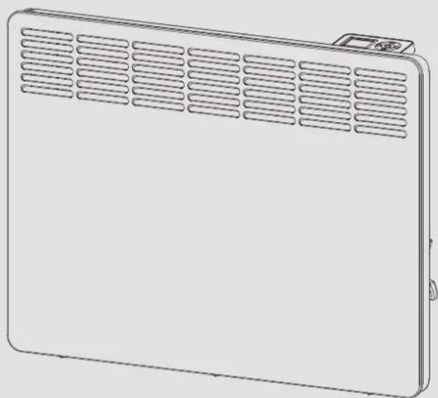
1 Programming unit
2 ON/OFF switch
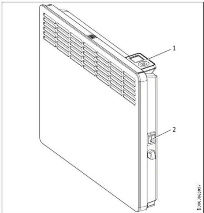
4.1 Programming unit
The programming unit is located at the top right of the appliance.
1 Display
2 User interface
4.1.1 User interface
| Button Designation Description | ||
| "Standby" key | Switch on the programming unit;Put programming unit and heating appliance into standby mode | |
| "OK" button | Selection;Confirm settings | |
| "Menu" key | Call up and exit menu | |
| "+" key | Call up menu items;Change settings | |
| "*" key Call up menu items; | Change settings | |
4.1.2 Display
If no user action occurs for 20 seconds, the backlight switches off. Press any button to switch the background lighting on again.
Symbols
 | |
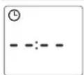
| Time display:Indication of the current time or a programmed start time | |
| Timer mode:The appliance heats in accordance with the enabled time program. | |
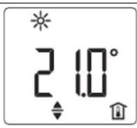
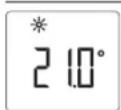
| Comfort mode:The appliance maintains the set comfort temperature.Standard setting: 21.0 °C. Use this setting for comfortable room temperatures when someone is present. | |
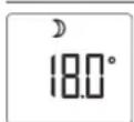
| Setback mode:The appliance maintains the set setback temperature.Standard setting: 18.0 °C. Use this setting e.g. at night or when absent for several hours. | |
| Frost protection:The frost protection symbol is displayed if the set room temperature is set to 7.0 °C.Use this setting to protect an unused room from frost damage. | |
| Adaptive start:In timer mode, the heating appliance switching times are adjusted to ensure that, at the programmed start time, the respective set room temperature is already reached.Conditions: The "adaptive start" function is enabled (see chapter "Settings / Standard menu"). | |
| Symbol Description | |
| Window open detection:To avoid unnecessary energy consumption while venting, the appliance automatically switches to frost protection mode for one hour when a window is open. The "window open detection" symbol flashes. After venting, frost protection mode can be terminated manually by pressing "+". The appliance then heats to the set room temperature again.Conditions: Window open detection is enabled (see chapter "Settings / Standard menu"). | |
| User interface lock:To lock or unlock the user interface, press and hold "+" and "-" simultaneously for 5 seconds. | |
| Heating enabled:The appliance is heating to maintain the set room temperature. | |
| Room temperature display | |
| Editable parameter:The parameter shown can be changed using "+" and "-" . | |
| External input (FP):CWM U series appliances can be connected to an external control unit. Depending on the control unit settings, the appliance heats at specific times of the day in comfort, setback or frost protection mode, or does not heat at all. | |
| Days the week:1 = Monday, 2 = Tuesday ... 7 = Sunday | |
4.2 Switching the appliance on and off

Note
For a short time after initial start-up and after longer breaks in use, a smell may develop.
The appliance is ready for operation as soon as it has been fixed to the wall and plugged into the mains.
▶ Switch the appliance on or off using the ON/OFF switch on the right-hand side of the appliance.
▶ Switch the appliance off when not in use for longer periods (e.g. during the summer months).
All settings remain intact after switching off or after an interruption to the power supply. This appliance is equipped with a power reserve that ensures the day of the week and the time are saved for several hours.

Note
If the appliance was in timer mode before being switched off for a longer period of time, you will be prompted to set the day and time after switching it on. Until this setting is made, the appliance will operate in comfort mode.
4.3 Standby mode
Material losses In standby mode, the appliance will not switch on heating under any circumstances. There will be no frost protection.
▶ To switch on the programming unit, press "Standby". The standard display appears.
▶ To put the programming unit and the heating appliance into standby mode, press "Standby". The display shows "----".
5. Settings
5.1 Standard display
D0000072134
The default display is continuously displayed. If no user action is performed for longer than 20 seconds while in the menu, the appliance automatically switches to the default display.
The default display shows the current set room temperature as well as the "Editable parameter" symbol. You can use "+" and "-" to change the set room temperature.
If the set room temperature corresponds to one of the values set for the comfort or setback temperature, the symbol for the corresponding operating mode (comfort mode, setback mode) appears in the menu bar.
The set room temperature can also be changed manually when in timer mode. The changed set room temperature is maintained until the next programmed switching point is reached.
5.2 Standard menu
To access the standard menu, briefly press "Menu". You can now call up the following menu items:
Display Description
 | Select day of the week and time |
 | Select comfort temperatureThe comfort temperature must be set at least 0.5 °C higher than the setback temperature. |
 | Select setback temperature |
 | Switch "Window open detection" function on and off |
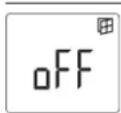
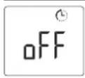
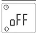 | Select time program (Pro1, Pro2, Pro3, off) or external input (FP) |
 | Switch "Adaptive start" function on and off |
To change the setting of a menu item, call it up by pressing "+" and "-" . Press the "OK" button.
As soon as the "Editable parameter" symbol appears, you can change the setting of the menu item with "+" and "-" . Press "OK" to save the setting.
To exit the standard menu, briefly press "Menu". The standard display appears.
5.3 Configuration menu
Display Description
I1-I2 Actual values
Pro1-Pro3 Time programs
P1-P5 Parameters
In the configuration menu, you can call up actual values, program time programs for timer mode and set parameters.
To access the configuration menu, press and hold "Menu". After approx. 3 seconds, actual value l1 is displayed.
Use "+" and "-" to switch between the individual actual values, time programs and parameters.
To exit the configuration menu, briefly press "Menu". The standard display appears.
5.3.1 Actual values
The following actual values can be called up:
| Display Description Unit | ||
| I1 | Actual room temperature | [°C] I [°F] |
| I2 | Relative heating time(The counter can be reset via parameter P5.) | [h] |

Note
The counter for relative heating time (I2) counts in complete hours how long the appliance heats for. When the appliance is switched off, any heating phase of less than 60 minutes is not recorded.
5.3.2 Time programs
There are three time programs available for using the appliance in timer mode. Time programs Pro1 and Pro2 are factory-set. Time program Pro3 can be set according to your individual requirements.
Display Description
| Pro1 | Time program "Daily"- Repeated: Monday to Sunday |
| Pro2 | Time program "Weekdays"- Repeated: Monday to Friday |
| Pro3 | Time program "User defined"- up to 14 comfort phases, freely configurable |

Note
To use timer mode, select the required time program in the standard menu (see chapter "Settings / Standard menu").

Note
Ensure the day of the week and the time are set correctly when setting the time programs.

Note
The following applies to all time programs (Pro1, Pro2, Pro3):
If the end time is later than 23:59 h, the end time will automatically be moved to the next day of the week. The comfort phase is maintained past midnight and will end on the next day at the set end time.
Time programs Pro1 and Pro2
You can specify the comfort mode start and end times with time programs Pro1 and Pro2. During this time period, the appliance heats to the set comfort temperature. Outside this specified time period, the appliance operates in setback mode. This results in a comfort and a setback phase that are repeated daily (Pro1) or every weekday (Pro2).
Theses phases are factory-set as follows:
- 08:00 h - 22:00 h: Comfort mode
- 22:00 h - 08:00 h: Setback mode

Note
When time program Pro2 is enabled, the appliance operates exclusively in setback mode during the weekend.
To adapt time programs Pro1 and Pro2 according to your needs, proceed as follows:
▶ In the configuration menu, use "+" and "-" to call up the required time program.
▶ Press the "OK" button.
The start time for comfort mode is displayed.
▶ Use "+" and "-" to set the required start time.
▶ Press the "OK" button.
The end time for comfort mode is displayed.
▶ Use "+" and "-" to set the required end time.
▶ Press "OK" to save.
Time program Pro3
You can use time program Pro3 to specify up to 14 separate comfort phases which are repeated weekly.
To configure a comfort phase in time program Pro3:
▶ In the configuration menu, use "+" and "-" to call up time program Pro3.
▶ Press the "OK" button.
The display shows "3---".
▶ Press the "OK" button.
A day of the week or a group of days is displayed.
▶ Use "+" and "-" to select the required day or group of days.
▶ Press the "OK" button.
The start time for comfort mode is displayed.
▶ Use "+" and "-" to set the required start time.
▶ Press the "OK" button.
The end time for comfort mode is displayed.
▶ Use "+" and "-" to set the required end time.
▶ Press the "OK" button.
Comfort phase "3-01" has been configured.
▶ To configure a further comfort phase, use "+" and "-" in time program Pro3 to select display "3---". Proceed as describe above.

To reset the selected comfort phases, activate parameter P4.
▶ Please note that activating parameter P4 resets all time programs (Pro1, Pro2, Pro3) to the factory setting.
5.3.3 Parameters
You can call up the following parameters:
| Display Description Options | ||
| P1 | Room temperature offset | ± 3 ^ ± 5 ^ |
| P2 Time format | 12 h | 24 h | |
| P3 | Temperature display units | ^ ^ |
| P4 Reset time programs (timer mode). | on | off | |
| P5 | Reset relative heating time | on | off |
To change the value of a parameter, use "+" and "-" to call up the relevant parameter. Press the "OK" button.
As soon as the "Editable parameter" symbol appears, you can change the parameter value with "+" and "-". Press "OK" to save the selected value.
P1: Room temperature offset
Uneven temperature distribution in the room can result in a difference between displayed actual temperature I1 and the room temperature you measure yourself. To compensate for this difference, a room temperature offset of ±3 ^ can be set via parameter P1.
Example: The appliance indicates l_1 = 21.0 ^ . You have measured a room temperature of 20.0 ^ . There is a difference of 1.0 ^ .
▶ To compensate for the difference, select an offset of P1 = -1.0.
P2: Time format
Parameter P2 is used to specify whether to display the time in 12 hour or 24 hour format.
P3: Temperature display units
Parameter P3 is used to specify whether the room temperature is displayed in degrees Centigrade [°C] or in degrees Fahrenheit [°F].
P4: Reset time programs
.Activating parameter P4 resets all time programs to the factory setting.
P5: Reset relative heating time
Activating parameter P5 resets the counter for relative heating time (I2).
6. Cleaning, care and maintenance
The appliance contains no user serviceable parts.

Material losses
- Never spray cleaning spray into the air slot.
-
Ensure that no moisture can enter the appliance.
-
If a pale brownish discolouration appears on the appliance casing, wipe it off with a damp cloth.
- Clean the appliance when cold with ordinary cleaning products. Avoid abrasive or corrosive cleaning products.

Note
We recommend having the control components checked as part of regular maintenance.
▶ Have a qualified contractor check the safety and control components no more than 10 years after commissioning.
7. Troubleshooting
| Problem Cause Remedy | ||
| Room does not get warm enough. Ap- pliance does not get hot. | Temperature set too low on the appliance. | Check the selected room temperature. Adjust if nec- essary. |
| No power supply. | Check position of the ON/OFF switch, RCD and fuse/MCB in your fuse box. | |
| Room does not get warm enough al- though the appliance is hot. | Overheating. High limit safety cut-out limits heating output. | Eliminate the cause (dirt or obstructions at the air inlet or outlet). Observe minimum clearances. |
| The heat demand of the room is higher than ap- pliance output. | Remove heat losses (Close windows and doors. Avoid constant venting.) | |
| Room gets too hot. | Temperature set too high on the appliance. | Check the selected room temperature. Adjust if nec- essary. |
| Detected room tempera- ture does not match actu- al room temperature. | Avoid obstructions to air change between appliance and indoor air. | |
| Window open de- tection does not respond. | Appliance does not detect a pronounced tempera- ture drop due to venting. (Window open detection requires previously sta- ble room temperature.) | Wait a while after making settings on the appliance, until the room temperature has fully stabilised. |
| Avoid obstructions to air change between appliance and indoor air. | ||
| Manually switch the appli- ance into standby mode for the duration of venting. | ||
| Window open detection is not enabled. | Switch on window open detection in the standard menu. | |
| Problem Cause Remedy | ||
| "Adaptive start" function does not work as required. | This function is only effective in timer mode. | Use the timer mode for optimised heating convenience. |
| Severely fluctuating room temperature or the appliance learning procedure has not been completed. | Wait a few days for behaviour to stabilise. | |
| "Adaptive start" function is not enabled. | Switch on the "Adaptive start" function in the standard menu. | |
| Appliance is in "FP" program but does not respond to external input. | When the appliance does not detect a signal at the external input, it heats in comfort mode. | Check external control unit and its settings. Wiring must be installed correctly and with correct polarity. |
| "Err" or "E..." is displayed. | Internal fault detected. | Notify the qualified contractor. |
If you cannot remedy the fault, contact your qualified contractor. To facilitate and speed up your request, provide the number from the type plate (000000-0000-000000).
INSTALLATION
8. Safety
Only a qualified contractor should carry out installation, commissioning, maintenance and repair of the appliance.
8.1 General safety instructions
We guarantee trouble-free function and operational reliability only if original accessories and spare parts intended for the appliance are used.

CAUTION Burns
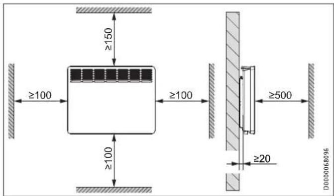
- Only mount the appliance on a vertical wall that is temperature-resistant to at least 85 °C.
- Maintain the minimum clearances to adjacent objects.

Material losses
- Never install the appliance directly below a wall socket.
- Ensure that the power cable is not in contact with any appliance components.
8.2 Instructions, standards and regulations

Note
Observe all applicable national and regional regulations and instructions.
9. Appliance description
9.1 Standard delivery
The following are delivered with the appliance:
- Wall mounting bracket (hooked into the appliance)
10. Installation
10.1 Installation site
Installation in bathrooms

WARNING Electrocution
When installing the appliance in rooms with a bath and/or shower, the appliance may only be connected to a standard socket outside safety zones 0, 1 and 2. The socket must be at least 600 mm away from a bath or shower. If in doubt, consult a qualified contractor.
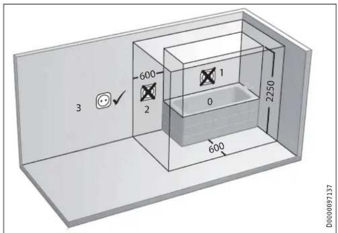
Electrical safety zones in the bathroom
10.2 Minimum clearances
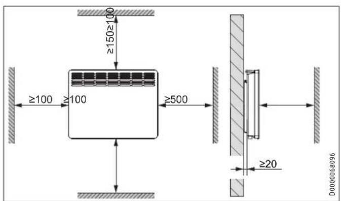
10.3 Installing the wall mounting bracket
The appliance is intended for wall mounting using the wall mounting bracket supplied. The appliance may only be installed horizontally.

Note
- The wall mounting bracket can be used as a template for wall mounting. This ensures sufficient clearance from the floor.
- Use a spirit level if the floor is uneven or sloping.
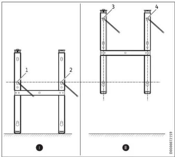

▶ Unhook the wall mounting bracket from the appliance.
▶ Place the centred wall mounting bracket horizontally on the floor. Mark holes 1 and 2.
▶ Lift up the wall mounting bracket so that its lower holes match up with the markings you have just made on the installation wall.
▶ Mark holes 3 and 4 on the installation wall.
▶ Drill the holes at the 4 markings.
▶ Secure the wall mounting bracket with suitable fixing materials (screws, rawl plugs). With the vertical slots, you can compensate for an offset fixing hole.
10.4 Appliance installation
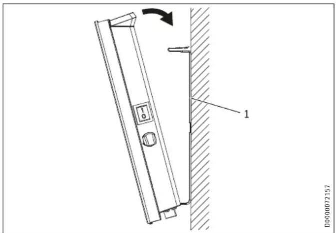
1 Wall mounting bracket
▶ Hook the appliance onto the bottom tabs of the wall mounting bracket by the slots in the back of the appliance.
▶ Place the appliance in an upright position.
- Secure the appliance by pushing it towards the wall until it audibly snaps into place in the two upper springs on the wall mounting bracket.
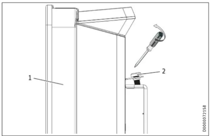
1 Appliance
2 Locking screw
- Secure the appliance against unintentional release using the supplied locking screw on the left-hand side of the wall mounting bracket.
10.5 Removing the appliance
▶ Undo and remove the locking screw from the wall mounting bracket.
▶ To release the appliance, push down the springs at the top of the wall mounting bracket.
▶ Tilt the appliance away from the wall and lift it off the bottom tabs on the wall mounting bracket.
10.6 Electrical connection

WARNING Electrocution
Carry out all electrical connection and installation work in accordance with national and regional regulations.

WARNING Electrocution
- In the case of a permanent connection, the appliance must be able to be separated from the power supply by an isolator that disconnects all poles with at least 3 mm contact separation.
- Do not install the appliance with a fixed power cable.

Note
- Observe the type plate. The specified voltage must match the mains voltage.
- Ensure the on-site supply cable has an adequate cross-section.

Note
In a non-domestic environment and in case of particularly high demands on the appliance, such as permanent continuous operation, we recommend installing the appliance as a permanent connection with a junction box.
Only an authorised electrician is allowed to make the permanent connection to a junction box.

WARNING Electrocution
- Provide appropriate strain relief when making the connection to a junction box.
- Ensure that the appliance is connected to the earth conductor.
- Seal the trimmed cable ends again correctly with wire ferrules.
10.6.1 CWM P series
The appliance is delivered fully wired. The following electrical connections are permissible:
| CWM 500-3000 P | |
| Connection to a freely accessible standard socket with matching plug | X |
| Permanent connection to an appliance junction box with earth conductor | X |
- If connecting the appliance via a socket, ensure that this is easily accessible once the appliance has been installed.
- If connecting the appliance permanently, trim the power cable so that it leads directly to the appliance connection socket. Ensure that, after trimming the power cable, the appliance can still be removed from the wall without a problem.
10.6.2 CWM U series
The appliance is delivered with a power cable without a plug.
▶ When wiring the appliance in permanently, connect the 4-core cable to a connection socket as illustrated:
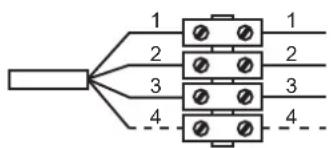
flowchart
graph TD
    A[" "] --> B["1"]
    A --> C["2"]
    A --> D["3"]
    A --> E["4"]
    B --> F["1"]
    B --> G["2"]
    B --> H["3"]
    B --> I["4"]
    C --> J["1"]
    C --> K["2"]
    C --> L["3"]
    C --> M["4"]
    D --> N["1"]
    D --> O["2"]
    D --> P["3"]
    D --> Q["4"]
    E --> R["1"]
    E --> S["2"]
    E --> T["3"]
    E --> U["4"]
D0000068123
1 Neutral conductor = blue
2 Live = brown
3 Earth conductor = green/yellow
4 Control cable = black
There are 3 possible ways to connect the appliance:
- Appliance connection without control cable
Unregulated appliance. The control cable is not connected. In this case, insulate the control cable.
- Temperature setback via control cable
To reduce the temperature to the set setback temperature, the black control cable is activated via an external electronic contact (e.g. a time switch).
- Control cable connected to external control unit
The appliance can be connected to any control unit that issues the following waveforms as control signals.
| Instruction Oscilloscope Operating mode | Heating temperature | ||
| No electrical power | Comfort mode | Subject to set comfort temperature | |
| Complete oscill-lation 230 V | 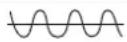 | Setback mode | Subject to set setback temperature |
| Semi-oscillation negative -115 V | 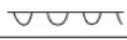 | Frost protection | Frost protection tem-perature |
| Semi-oscillation positive +115 V | 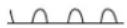 | Stop | None |
| Full oscillation 230 V for 3 sec-onds | 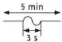 | Comfort mode -1 °C | 1 °C less than the set comfort temperature |
| Full oscillation 230 V for 7 sec-onds | 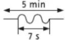 | Comfort mode -2 °C | 2 °C less than the set comfort temperature |
11. Commissioning
The appliance is ready for operation as soon as it has been fixed to the installation wall and plugged into the mains.
▶ Remove the protective film from the programming unit.
12. Troubleshooting
The power cable must only be replaced (for example if damaged) by a qualified contractor authorised by the manufacturer, using an original spare part.
13. Appliance handover
Explain the functions of the appliance to the user. Draw special attention to the safety instructions. Hand over the operating and installation instructions to the user.
14. Specification
14.1 Dimensions and connections
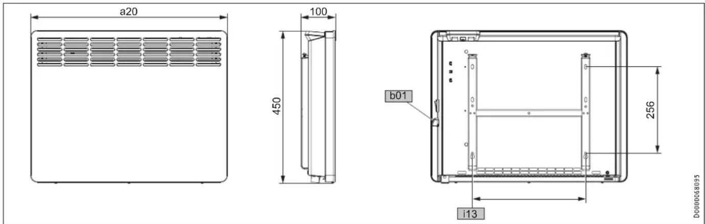
| CWM 500 | P/U | CWM 750 P/U | CWM 1000 P/U | CWM 1500 P/U | CWM 2000 P/U | CWM 2500 P/U | CWM 3000 P/U | |||
| a20 | Appliance | Width | mm | 348 | 426 | 426 | 582 | 738 | 894 | 1050 |
| b01 | Entry electrical cables | |||||||||
| i13 | Wall mounting bracket | Horizontal hole spacing | mm | 101 | 179 | 179 | 335 | 491 | 647 | 803 |
14.2 Energy consumption data
The product data complies with EU regulations relating to the Directive on the ecodesign of energy related products (ErP).
Product information on electric individual room heaters to regulation (EU) 2015/1188
| CWM 500 P/U | CWM 750 P/U | CWM 1000 P/U | CWM 1500 P/U | CWM 2000 P/U | CWM 2500 P/U | CWM 3000 P/U | ||
| CWM P | 200254 | 200255 | 200256 | 200257 | 200258 | 200259 | 200260 | |
| CWM U | 200261 | 200262 | 200263 | 200264 | 200265 | 200266 | 200267 | |
| Manufacturer | STIEBELTRON | STIEBELTRON | STIEBELTRON | STIEBELTRON | STIEBELTRON | STIEBELTRON | STIEBELTRON | |
| Heating output | ||||||||
| Rated heating output P_nom | kW | 0,5 | 0,8 | 1,0 | 1,5 | 2,0 | 2,5 | 3,0 |
| Minimum heating output (standard value) P_min | kW | 0,0 | 0,0 | 0,0 | 0,0 | 0,0 | 0,0 | 0,0 |
| Maximum continuous heating output P_max,c | kW | 0,5 | 0,8 | 1,0 | 1,5 | 2,0 | 2,5 | 3,0 |
| Auxiliary power consumption | ||||||||
| At rated heating output el_max | kW | 0.000 | 0.000 | 0.000 | 0.000 | 0.000 | 0.000 | 0.000 |
| At minimum heating output el_min | kW | 0.000 | 0.000 | 0.000 | 0.000 | 0.000 | 0.000 | 0.000 |
| In standby el_SB | kW | 0.000 | 0.000 | 0.000 | 0.000 | 0.000 | 0.000 | 0.000 |
| Type of heating output/room temperature control | ||||||||
| Single stage heating output, no room temperature control | - | - | - | - | - | - | - | |
| Two or more manually selectable stages, no room temperature control | - | - | - | - | - | - | - | |
| Room temperature control with mechanical thermostat | - | - | - | - | - | - | - | |
| With electronic room temperature control | - | - | - | - | - | - | - | |
| Electronic room temperature control and time of day control | - | - | - | - | - | - | - | |
| Electronic room temperature control and day of week control | x | x | x | x | x | x | x | |
| Other control options | ||||||||
| Room temperature control with presence detection | - | - | - | - | - | - | - | |
| Room temperature control with window open detection | x | x | x | x | x | x | x | |
| With remote control option | - | - | - | - | - | - | - | |
| With adaptive control of heating start | x | x | x | x | x | x | x | |
| With operating time limitation | - | - | - | - | - | - | - | |
| With black bulb sensor | - | - | - | - | - | - | - | |
14.3 Data table
| CWM 500 P/U | CWM 750 P/U | CWM 1000 P/U | CWM 1500 P/U | CWM 2000 P/U | CWM 2500 P/U | CWM 3000 P/U | ||
| CWM P | 200254 | 200255 | 200256 | 200257 | 200258 | 200259 | 200260 | |
| CWM U | 200261 | 200262 | 200263 | 200264 | 200265 | 200266 | 200267 | |
| Electrical data | ||||||||
| Connected load | W | 500 | 750 | 1000 | 1500 | 2000 | 2500 | 3000 |
| Power supply | 1/N/PE ~ 230 V | 1/N/PE ~ 230 V | 1/N/PE ~ 230 V | 1/N/PE ~ 230 V | 1/N/PE ~ 230 V | 1/N/PE ~ 230 V | 1/N/PE ~ 230 V | |
| Rated current | A | 2.2 | 3.3 | 4.3 | 6.5 | 8.7 | 10.9 | 13.0 |
| Frequency | Hz | 50/- | 50/- | 50/- | 50/- | 50/- | 50/- | 50/- |
| Energy data | ||||||||
| Room heating seasonal efficiency ηs | % | 39 | 39 | 39 | 39 | 39 | 39 | 39 |
| Dimensions | ||||||||
| Height | mm | 450 | 450 | 450 | 450 | 450 | 450 | 450 |
| Width | mm | 348 | 426 | 426 | 582 | 738 | 894 | 1050 |
| Depth | mm | 100 | 100 | 100 | 100 | 100 | 100 | 100 |
| Weights | ||||||||
| Weight | kg | 4.0 | 4.6 | 4.6 | 6.0 | 7.7 | 9.2 | 10.9 |
| Versions | ||||||||
| Frost protection setting | °C | 7 | 7 | 7 | 7 | 7 | 7 | 7 |
| Version | Wall mounted appliance | Wall mounted appliance | Wall mounted appliance | Wall mounted appliance | Wall mounted appliance | Wall mounted appliance | Wall mounted appliance | |
| IP rating | IP24 | IP24 | IP24 | IP24 | IP24 | IP24 | IP24 | |
| Protection class | I | I | I | I | I | I | I | |
| Colour | Alpine white | Alpine white | Alpine white | Alpine white | Alpine white | Alpine white | Alpine white | |
| Values | ||||||||
| Setting range | °C | 5-30 | 5-30 | 5-30 | 5-30 | 5-30 | 5-30 | 5-30 |
Guarantee
The guarantee conditions of our German companies do not apply to appliances acquired outside of Germany. In countries where our subsidiaries sell our products a guarantee can only be issued by those subsidiaries. Such guarantee is only granted if the subsidiary has issued its own terms of guarantee. No other guarantee will be granted.
We shall not provide any guarantee for appliances acquired in countries where we have no subsidiary to sell our products. This will not affect warranties issued by any importers.
Environment and recycling
We would ask you to help protect the environment. After use, dispose of the various materials in accordance with national regulations.
REMARQUES PARTICULIÈRES
UTILISATION
10.2 Distances minimales
WAARSCHUWING verbranding
WAARSCHUWING verbranding
WAARSCHUWING verbranding
WAARSCHUWING oververhitting
1 Bedieningseenheid
2 Netschakelaar
4.1 Bedieningseenheid
www.stiebel-eltron.com.au
Austria
STIEBEL ELTRON Ges.m.b.H.
Plant C3, XEDA International Industry City
Xiqing Economic Development Area
300085 Tianjin
Tel. 022 8396 2077 | Fax 022 8396 2075
info@stiebeleltron.cn
www.stiebeleltron.cn
Czech Republic
STIEBEL ELTRON spol. s r.o.
Urzhumskaya street 4,
building 2 | 129343 Moscow
Tel. 0495 7753889 | Fax 0495 7753887
info@stiebel-eltron.ru
www.stiebel-eltron.ru
Slovakia
STIEBEL ELTRON Slovakia, s.r.o.
Hlavná 1 | 058 01 Poprad
Tel. 052 7127-125 | Fax 052 7127-148
info@stiebel-eltron.sk
www.stiebel-eltron.sk
Switzerland
STIEBEL ELTRON AG
Industrie West
Gass 8 | 5242 Lupfig
Tel. 056 4640-500 | Fax 056 4640-501
info@stiebel-eltron.ch
www.stiebel-eltron.ch
Thailand
STIEBEL ELTRON Asia Ltd.
469 Moo 2 Tambol Klong-Jik
Amphur Bangpa-In | 13160 Ayutthaya
Tel. 035 220088 | Fax 035 221188
info@stiebeleltronasia.com
www.stiebeleltronasia.com
United Kingdom and Ireland
STIEBEL ELTRON UK Ltd.
Unit 12 Stadium Court
Stadium Road | CH62 3RP Bromborough
Tel. 0151 346-2300 | Fax 0151 334-2913
info@stiebel-eltron.co.uk
www.stiebel-eltron.co.uk
United States of America
STIEBEL ELTRON, Inc.
17 West Street | 01088 West Hatfield MA
Tel. 0413 247-3380 | Fax 0413 247-3369
info@stiebel-eltron-usa.com
www.stiebel-eltron-usa.com

Irrtum und technische Änderungen vorbehalten! | Subject to errors and technical changes! | Sous réserve d'erreurs et de modifications techniques! | Onder voorbehoud van vergissingen en technische wijzigingen! | Salvo error o modificación técnica! | Excepto erro ou alteração técnica | Zastrzeżone zmiany techniczne i ewentualne błędy | Omyly a technické zmény jsou vyhrazeny! | A muszaki változtalások és tivedések jogát fenntartjuk! | Otcутствие ошибok не гарантируется. Возможны технические изменения. | Chyby a technické zmeny sú vyhradené! Stand 9627