
CNS 150 F - Electric heater STIEBEL ELTRON - Free user manual and instructions
Find the device manual for free CNS 150 F STIEBEL ELTRON in PDF.
| Product type | Electric convector |
| Brand | Stiebel Eltron |
| Model | CNS 150 F |
| Power | 1.5 kW |
| Power supply | 1/N ~ 230 V |
| Temperature setting range | 6 ... 30 °C |
| Frost protection | Yes, set to ~6 °C |
| Protection class | II |
| Protection rating | IP 24 |
| Dimensions (wall-mounted) - Height | 450 mm |
| Dimensions (wall-mounted) - Width | 590 mm |
| Dimensions (wall-mounted) - Depth | 100 mm |
| Dimensions (on feet) - Total height | 555 mm |
| Dimensions (on feet) - Width | 590 mm |
| Dimensions (on feet) - Depth | 305 mm |
| Weight | 6.0 kg |
| Minimum safety distances | Top: 250 mm, Bottom: 100 mm, Sides: 100 mm, Front: 500 mm, Rear: 22 mm |
| Mounting type | Wall-mounted (bracket provided) or on feet |
| Cleaning and maintenance | Damp cloth, non-abrasive cleaners; do not spray any spray |
| Warranty | To be claimed in the country of purchase |
Frequently Asked Questions - CNS 150 F STIEBEL ELTRON
User questions about CNS 150 F STIEBEL ELTRON
0 question about this device. Answer the ones you know or ask your own.
Ask a new question about this device
Download the instructions for your Electric heater in PDF format for free! Find your manual CNS 150 F - STIEBEL ELTRON and take your electronic device back in hand. On this page are published all the documents necessary for the use of your device. CNS 150 F by STIEBEL ELTRON.
USER MANUAL CNS 150 F STIEBEL ELTRON
natural_image
Pure diagram of a rectangular frame with horizontal lines and dots, no text or symbols present.BEDIENUNG
natural_image
Pure technical diagram of a mechanical component without any text, numbers, or symbols26_07_31_0037
- General information 12
1.1 Document information 12
1.2 Key to symbols 12 - Safety 13
2.1 Intended use 13
2.2 Safety information 13
2.3 CE designation 14
2.4 Test symbols 14 - Appliance description 14
- Operation 14
4.1 Description of the user interface 14
4.2 Frost protection 14
4.3 Limiting the temperature controller 15
4.4 Shutting down 15 - Cleaning, care and maintenance 15
- What to do if ... 15
INSTALLATION
- Safety 16
7.1 General safety instructions 16
7.2 Instructions, standards and regulations ____ 16 - Appliance description 16
8.1 Standard delivery 16 - Installation 16
9.1 Installation with wall mounting bracket 16
9.2 Installation with feet 17
9.3 Power supply 17 - Troubleshooting 17
- Appliance handover 17
- Specification 18
12.1 Dimensions of wall mounted version 18
12.2 Dimensions of mobile floorstanding version ____ 18
12.3 Specification table 19
ENVIRONMENT AND RECYCLING
CUSTOMER SERVICE AND WARRANTY
1. General information
1.1 Document information

Read these instructions carefully before using the appliance and retain them for future reference. Pass on the instructions to any new users.
1.2 Key to symbols
1.2.1 Layout of safety information
Safety information comprises a warning symbol, a keyword and a text giving information. Safety information is printed on a grey background.
Example:

DANGER Electrocution Install the appliance in such a way that control equipment...
1 Symbol (see chapter on warning symbols/symbols)
2 Keyword (see chapter on keywords)
3 Description (see chapter on warning symbols/symbols)
4 Information text
1.2.2 Keywords
KEYWORD Description
| DANGER | The keyword DANGER indicates information which must be observed, otherwise serious injury or death will result. |
| WARNING | The keyword WARNING indicates information that must be observed, otherwise serious injury or death may result. |
| CAUTION | The keyword CAUTION indicates information that must be observed, otherwise relatively serious or light injuries may result. |
1.2.3 Warning symbols/symbols
Warning symbol Description

Injury

Electrocution

Burns or scalding

Other situations

Fire

Never cover the appliance

Appliance disposal
1.2.4 Text symbols and layout in this documentation

Read the text next to this symbol carefully.
» The "»" symbol indicates that you should do something. The action you need to take is described step by step.
-Passages with the ^"" symbol show you lists of items.
1.2.5 Information on the appliance

Never cover the appliance
1.2.6 Units of measurement

The dimensions in this document are given in mm. Any alternative units of measurements are specified accordingly.
2. Safety
2.1 Intended use
This appliance is designed to heat living areas.
Any other use beyond that described shall be deemed inappropriate. Observation of these instructions is also part of the correct use of this appliance. Any modifications or conversions to the appliance void all warranty rights.
2.2 Safety information
Operate the appliance only when fully installed and with all safety equipment fitted.

WARNING Fire
Never operate this appliance ...
- in rooms where the appliance is at risk of fire or explosion as a result of chemicals, dust, gases or vapours. - in the direct proximity of pipes or receptacles that carry or contain flammable or explosive materials.
- if work such as laying cables, grinding or sealing is carried out in the installation room.
- if sprays, floor polish or similar products containing napsan are used. Vent the room sufficiently before heating.
- if the minimum clearances to adjacent object surfaces are not maintained, for example to furniture, net curtains, curtains, textiles or other flammable materials (for minimum clearances, see specification chapter).
- if an appliance component is damaged, the appliance has fallen over or already had a fault.

WARNING Injury
Where children or persons with limited physical, sensory or mental capabilities are allowed to control this appliance, ensure that this will only happen under supervision or after appropriate instructions by a person responsible for their safety.
Children must be supervised to ensure that they never play with the appliance.

WARNING Fire
Never place any flammable, combustible or insulating objects or materials, such as laundry, blankets, magazines, containers with floor polish or napsan, spray cans or similar on the appliance or in direct proximity to it.

WARNING Burns
The surfaces of the appliance casing and the expelled air become hot during operation (more than 80 °C).

CAUTION Overheating
Never cover the appliance

Never step on the appliance.

When using the mobile floorstanding unit, observe the following:
- Never cover the power cable with a carpet or rug. Route the power cable away from walkways to prevent anyone tripping over the cable or knocking the appliance over.
- Avoid using an extension cable. If this is unavoidable, only use an undamaged extension cable with a sufficient cable cross-section for the full appliance output, as well as undamaged plugs or coupler plugs and adequate protective measures.
- Position the appliance on a solid base. On a soft base, the appliance can tip over or the air apertures can become blocked.
- Never move or carry the appliance by pulling on the power cable.
- If you use the appliance as a floorstanding unit, never install it in the bathroom, in similarly damp rooms or outside.
2.3 CE designation
The CE designation shows that the appliance meets all essential requirements according to the:
–Electromagnetic Compatibility Directive
-Low Voltage Directive
2.4 Test symbols
See type plate.
The type plate is located on the right on the exterior of the appliance.
3. Appliance description
The appliance is an electric direct heater and can be used as a wall mounted appliance or alternatively as a mobile floorstanding appliance with feet attached.
The appliance is suitable as a full heating system in bathrooms, for example, or for use between seasons and as a booster heater in smaller rooms, such as hobby and guest rooms.
The air in the appliance is heated by a heating element and expelled via natural convection through the air outlet grille at the top. Cool room air flows in through the apertures at the bottom of the appliance.
After mounting the appliance to the wall or attaching the feet, and making the electrical connection via the mains plug, the appliance is ready for operation.
4. Operation
4.1 Description of the user interface
» Switch the appliance ON via the switch on the r.h. side of the appliance.
» Set the required room temperature via the continuously variable temperature selector (for temperatures see specification chapter).
natural_image
Pure technical diagram of a mechanical component without any text, numbers, or symbols26_07_31_0037
As soon as the selected room temperature is reached, it is constantly maintained at this selected temperature through periodic heating (the output of the appliance must correspond at least to the required heat demand of the room).
If several appliances are installed in a single room, the setting at the temperature selector on each appliance can be different.
To avoid excessive power consumption when windows are open, you should stop the appliance while venting.
4.2 Frost protection
» Turn the temperature selector as far to the right as possible. In this position, the temperature controller switches on the heating element automatically if the room temperature drops below the frost protection temperature.
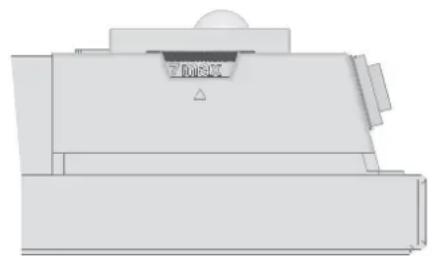
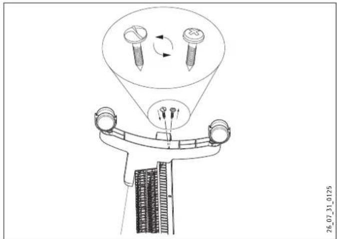
4.3 Limiting the temperature controller
Using the two pins fitted to the back of the control casing, you can fix the temperature controller at a certain setting or limit the temperature setting range.
» Break out the pins.
» To fix the selected temperature, push a pin into the hole opposite (see diagram).
1 Pin
2 Temperature selector
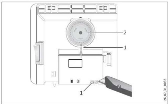
» To limit the temperature setting range, set the minimum and maximum values at the temperature selector, and push a pin for each into the slightly offset hole opposite (see diagram).
1 Pin
2 Temperature selector
4.4 Shutting down
» Move the switch on the right of the appliance to OFF.
5. Cleaning, care and maintenance
If a pale brownish discolouration appears on the appliance casing, wipe this off as soon as possible with a damp cloth. Clean the appliance when cold with ordinary cleaning products. Avoid abrasive or corrosive cleaning products.

CAUTION Fire
Never spray cleaning spray into the air slot.
Ensure that no moisture can enter the appliance.
As part of regular maintenance, we recommend also having the control components checked. The safety and control components should be checked by a contractor no more than ten years after commissioning.
6. What to do if ...
... the appliance does not heat up:
Check the temperature set at the appliance and the MCB/fuse in your fuse box.
The appliance has a safety temperature controller that shuts the appliance down if it overheats. After the cause has been removed (for example air outlet or inlet apertures covered) and the appliance has cooled down for a few minutes, operation starts again.
If you cannot remedy the fault, contact your contractor. To facilitate and speed up your enquiry, please provide the number on the type plate (no. XXXXXX - XXXX - XXXXXX):
7. Safety
Only qualified contractors should carry out the maintenance and repair of this appliance.
7.1 General safety instructions
We guarantee trouble-free function and operational reliability only if the original accessories and spare parts intended for the appliance are used.

DANGER Electrocution
If you mount the appliance on the wall, do so in such a way that control equipment cannot be touched by a person in the bath or shower.

CAUTION
- Only fit the wall mounted appliance to a vertical wall that is temperature-resistant to at least 85^ .
- Observe the minimum clearances to adjacent object surfaces (for minimum clearances see specification chapter).
- Never install the appliance directly below a wall socket.
- Ensure that the power cable is not in contact with any appliance components.
7.2 Instructions, standards and regulations

Observe all applicable national and regional regulations and instructions.

Observe the Building and Garage Regulations [or local regulations].
8. Appliance description
8.1 Standard delivery
-Wall mounting bracket (hooked into the appliance)
-Feet
-One-way Screws
9. Installation
9.1 Installation with wall mounting bracket
9.1.1 Installing the wall mounting bracket
You can also use the wall mounting bracket as a template for wall mounting; this ensures the required floor clearance.
» Unhook the wall mounting bracket.
» Place the centred wall mounting bracket level on the ground and mark holes 1 and 2.
» Lift up the wall mounting bracket so that its lower holes match up with the markings you have just made on the installation wall.
» Mark holes 3 and 4 on the installation wall.
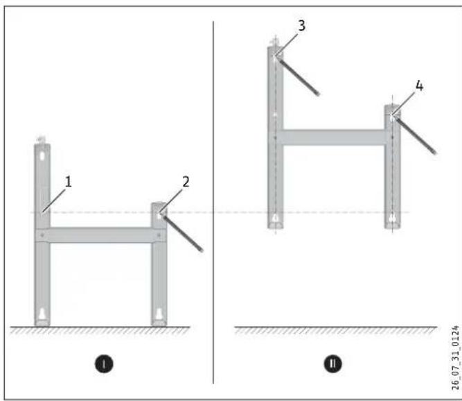
» Drill holes at all four markings. Secure the wall mounting bracket with suitable materials (screws, rawl plugs) depending on the type of wall. With the vertical slots, you can compensate for an offset fixing hole.
9.1.2 Appliance installation
» Hook the appliance by its slots in the back of the appliance on to all four tabs of the wall mounting bracket simultaneously.
» Push the appliance to latch it in position.
» Turn the locking bolt in the wall mounting bracket fully clockwise; this locks the appliance in place.
» Push the safety cap onto the locking bolt to prevent it from loosening.
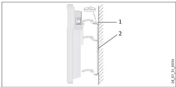
1 Locking bolt
2 Wall mounting bracket
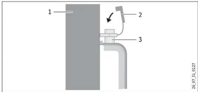
1 Appliance
2 Safety cap
3 Locking bolt
9.1.3 Dismounting the appliance
» Remove the safety cap from the locking bolt.
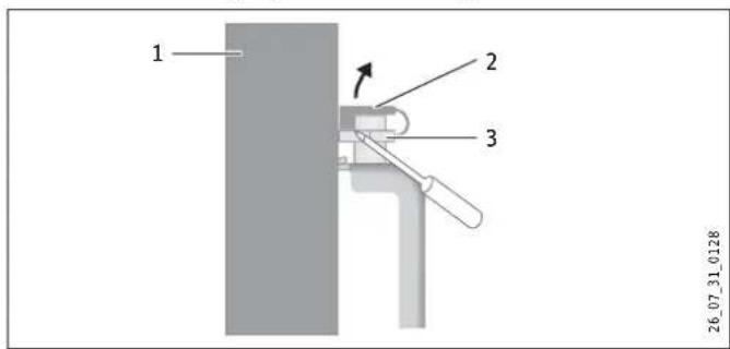
1 Appliance
2 Safety cap
3 Locking bolt
» Undo the locking bolt on the wall mounting bracket.
» Lift the appliance up slightly and pull it forwards and away from the wall mounting bracket.
9.2 Installation with feet
» Unhook the wall mounting bracket.
» Only remove both external left and right screws at the bottom of the appliance.
» Fit the feet to the bottom of the appliance in such a way that they are inserted into the recess at the back of the appliance.

Secure the feet with the One-way Screws supplied.
9.3 Power supply
» Ensure the on-site supply cable has an adequate cross-section.
» Ensure that a socket is installed at a distance of at least 10 cm from the side of the appliance.

DANGER Electrocution!
Carry out all electrical connection and installation work in accordance with relevant regulations.

DANGER Electrocution!
The appliance must be able to be separated from the mains power supply by an isolator that disconnects all poles with at least 3 mm contact separation.

DANGER Electrocution!
Do not install the appliance with a fixed power cable.

Observe the type plate. The specified voltage must match the mains voltage.
10. Troubleshooting
The power cable must only be replaced by a contractor using our original spare parts.
11. Appliance handover
Explain the functions of the appliance to the user. Draw special attention to the safety information. Hand the operating and installation instructions to the user.
12. Specification
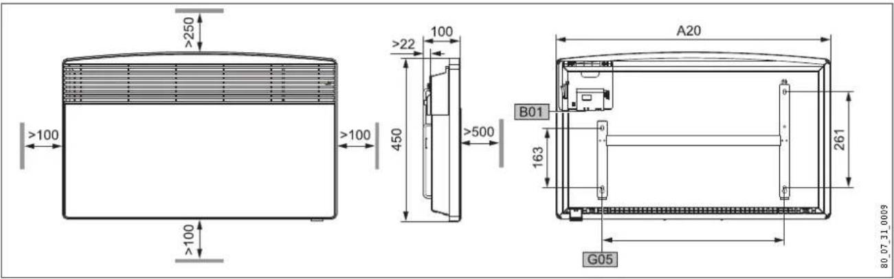
12.1 Dimensions of wall mounted version
CNS 75 F CNS 100 F CNS 125 F CNS 150 F CNS 175 F CNS 200 F CNS 250 F
A10 Appliance Height mm 450
| A20 | Appliance | Width | mm | 445 | 445 | 590 | 590 | 740 | 740 | 890 |
| A30 | Appliance | Depth | mm | 100 | ||||||
| A50 | Appliance | Minimum top clearance | mm | 250 | ||||||
| A51 | Appliance | Minimum bottom clearance | mm | 100 | ||||||
| A52 | Appliance | Minimum r.h. clearance | mm | 100 | ||||||
| A53 | Appliance | Minimum l.h. clearance | mm | 100 | ||||||
| A54 | Appliance | Minimum front clearance | mm | 500 | ||||||
| A55 | Appliance | Minimum rear clearance | mm | 22 | ||||||
| B01 | Electrical cable entry | |||||||||
| G05 | Wall mounting bracket | Hole spacing | mm | 195 | 195 | 343 | 343 | 491 | 491 | 639 |
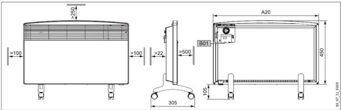
12.2 Dimensions of mobile floorstanding version
| CNS 75 F | CNS 100 F | CNS 125 F | CNS 150 F | CNS 175 F | CNS 200 F | CNS 250 F | ||||
| A10 | Appliance | Height | mm | 450 | ||||||
| A13 | Appliance | Height of adjustable feet | mm | 105 | ||||||
| A20 | Appliance | Width | mm | 445 | 445 | 590 | 590 | 740 | 740 | 890 |
| A30 | Appliance | Depth | mm | 305 | ||||||
| A50 | Appliance | Minimum top clearance | mm | 250 | ||||||
| A52 | Appliance | Minimum r.h. clearance | mm | 100 | ||||||
| A53 | Appliance | Minimum l.h. clearance | mm | 100 | ||||||
| A54 | Appliance | Minimum front clearance | mm | 500 | ||||||
| A55 | Appliance | Minimum rear clearance | mm | 22 | ||||||
| B01 | Electrical cable entry | |||||||||
12.3 Specification table
| Model | ||||||||
| Type | CNS 75 F | CNS 100 F | CNS 125 F | CNS 150 F | CNS 175 F | CNS 200 F | CNS 250 F | |
| Part number | 229789 | 229790 | 229791 | 229792 | 229793 | 229794 | 229795 | |
| Operating details | ||||||||
| Output | kW | 0.75 | 1.0 | 1.25 | 1.5 | 1.75 | 2.0 | 2.5 |
| Power connection | 1/N ~ 230 V | 1/N ~ 230 V | 1/N ~ 230 V | 1/N ~ 230 V | 1/N ~ 230 V | 1/N ~ 230 V | 1/N ~ 230 V | |
| Temperature setting range | ~ °C | 6 ... 30 | 6 ... 30 | 6 ... 30 | 6 ... 30 | 6 ... 30 | 6 ... 30 | 6 ... 30 |
| Frost protection | ~ °C | 6 | 6 | 6 | 6 | 6 | 6 | 6 |
| Safety class | II | II | II | II | II | II | II | |
| Protection IP 24, splash-proof | x | x | x | x | x | x | x | |
| Dimensions and weights | ||||||||
| Weight | kg | 4.6 | 4.6 | 6.0 | 6.0 | 7.2 | 7.2 | 8.4 |
Guarantee
For guarantees please refer to the respective terms and conditions of supply for your country.

The installation, electrical connection and first operation of this appliance should be carried out by a qualified

The company does not accept liability for failure of any goods supplied which have not been installed and open-accordance with the manufacturer's instructions.
Environment and recycling
Please help us to protect the environment by disposing of the packaging in accordance with the national regulations for waste processing.
UTILISATION 21
natural_image
Pure technical diagram of a mechanical component without any text, numbers, or symbols26_07_31_0037
natural_image
Pure technical diagram of a mechanical component without any text, numbers, or symbols26_07_31_0037
natural_image
Pure technical diagram of a mechanical component without any text, numbers, or symbols26_07_31_0037
natural_image
3D mechanical part diagram with no visible text or symbolsnatural_image
3D technical drawing of a mechanical component with no visible text or symbolsnatural_image
Pure technical diagram of a mechanical component without any text, numbers, or symbols26 07 31 0037
Unit 12 Stadium Court | Stadium Road
Bromborough | Wirral | CH62 3RP
Tel. 0151 346-2300 | Fax 0151 334-2913
info@stiebel-eltron.co.uk
www.stiebel-eltron.co.uk
Hungary
STIEBEL ELTRON Kft.
Nihon Stiebel Co. Ltd.
Ebara building 3F | 2-9-3 Hamamatsu-cho
Minato-ku | Tokyo 105-0013
Tel. 03 34364662 | Fax 03 34594365
info@nihonstiebel.co.jp
Netherlands
STIEBEL ELTRON Nederland B.V.
Daviottenweg 36
5222 BH 's-Hertogenbosch
Tel. 073 623-000 | Fax 073 623-1141
Urzhumskaya street, 4. | 129343 Moscow
Tel. 0495 775-3889 | Fax 0495 775-3887
info@stiebel-eltron.ru
www.stiebel-eltron.ru
Slovakia
TATRAMAT - ohrievace vody, s.r.o.
Hlavna 1 | 058 01 Poprad
Tel. 052 7127-125 | Fax 052 7127-148
info@stiebel-eltron.sk
www.stiebel-eltron.sk
Sweden
STENERGY
Vasagatan 14 | 545 30 Töreboda
Sales:
Tel. 0722 371900 | info@stiebel-eltron.se
Technique & Service:
Tel. 0150 54200 | info@heatech.se
www.stiebel-eltron.se
Switzerland
STIEBEL ELTRON AG
United States of America
STIEBEL ELTRON Inc.
17 West Street | West Hatfield, MA 01088
Tel. 413 247-3380 | Fax 413 247-3369
info@stiebel-eltron-usa.com
www.stiebel-eltron-usa.com
STIEBEL ELTRON

- BEDIENUNG
- INSTALLATION
- ENVIRONMENT AND RECYCLING
- CUSTOMER SERVICE AND WARRANTY
- General information
- Document information
- Key to symbols
- Layout of safety information
- Keywords
- Warning symbols/symbols
- Text symbols and layout in this documentation
- Information on the appliance
- Units of measurement
- Safety
- Intended use
- Safety information
- WARNING Fire
- WARNING Injury
- WARNING Burns
- CAUTION Overheating
- CE designation
- Test symbols
- Appliance description
- Operation
- Description of the user interface
- Frost protection
- Limiting the temperature controller
- Shutting down
- Cleaning, care and maintenance
- What to do if ...
- Safety
- General safety instructions
- DANGER Electrocution
- CAUTION
- Instructions, standards and regulations
- Appliance description
- Standard delivery
- Installation
- Installation with wall mounting bracket
- Installing the wall mounting bracket
- Appliance installation
- Dismounting the appliance
- Installation with feet
- Power supply
- Troubleshooting
- Appliance handover
- Specification
- Guarantee
- UTILISATION 21
- Hungary
- Netherlands
- Slovakia
- Sweden
- Switzerland
- United States of America
Brand : STIEBEL ELTRON
Model : CNS 150 F
Category : Electric heater