VIGI PS30 - Solar panel TP-LINK - Free user manual and instructions
Find the device manual for free VIGI PS30 TP-LINK in PDF.

| Product Type | Solar panel for surveillance system |
| Brand | TP-Link |
| Model | VIGI PS30 |
| Rated Power | 30 W |
| Output Voltage | 12 V DC |
| Dimensions (approx.) | 670 x 490 x 30 mm |
| Weight (approx.) | 3.5 kg |
| Panel Material | Polycrystalline Silicon |
| Certifications | CE, EU (2014/30, 2014/35, 2011/65, 2012/19) |
| Main Functions | Solar power supply, charge management, compatibility with VIGI controllers, remote supervision via VIGI app |
| Intended Use | Outdoor, for surveillance cameras, access points, network bridges |
| Protection Rating | IP65 (dust-tight and protected against water jets) |
| Warranty | Limited, see conditions on TP-Link website |
| Safety | Do not disassemble, do not expose to fire or extreme temperatures, use only supplied accessories |
| Maintenance and Cleaning | Clean with a soft dry cloth, avoid abrasive products |
| Spare Parts and Repairability | Contact TP-Link service for any repair or replacement |
| General Information | Recommended installation with VIGI controllers; follow the provided installation guide |
Frequently Asked Questions - VIGI PS30 TP-LINK
User questions about VIGI PS30 TP-LINK
0 question about this device. Answer the ones you know or ask your own.
Ask a new question about this device
Download the instructions for your Solar panel in PDF format for free! Find your manual VIGI PS30 - TP-LINK and take your electronic device back in hand. On this page are published all the documents necessary for the use of your device. VIGI PS30 by TP-LINK.
USER MANUAL VIGI PS30 TP-LINK
flowchart
graph TD
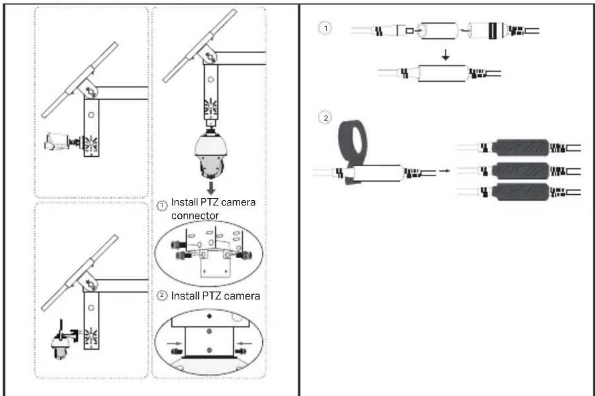
A["Stecker der PTZ-Kamera anbringen"] --> B["PTZ-Kamera montieren"]
B --> C["Final Assembly with Internal Components"]
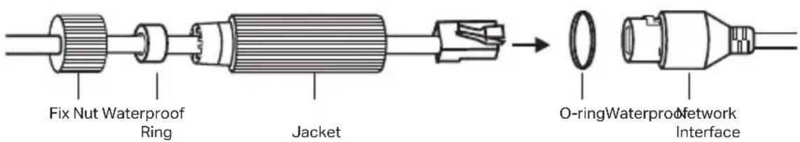
For detailed instructions on installing the product, load devices, and waterproof cable attachments, refer to Installation Guide included in the package.
*It is recommended to use VIGI solar panels with VIGI solar system controllers.
- Install the product.
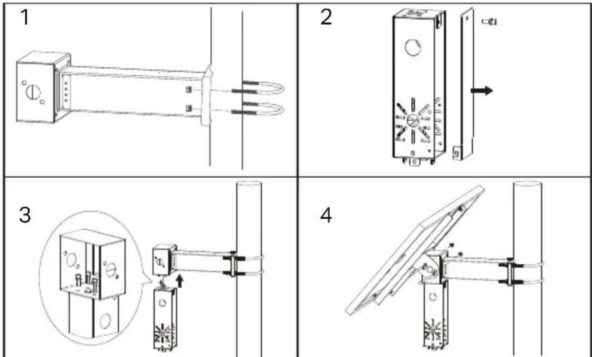
- Install load devices.
flowchart
graph TD
    A["Sensor Installation"] --> B["Add Sensor to Sensor"]
    B --> C{Adjust Sensor to PTZ Camera Connector}
    C --> D["Apply the sensor to PTZ Camera Connector"]
    D --> E["Final Assembly with 4x2x3 components"]
- Install waterproof cable attachments.
Configuration
Here is a typical network topology for the solar system controller.
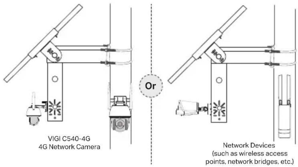
Step 1. Connect the four-pin female connector to the solar panel.
Step 2. Connect the RJ45 network interface of the solar panel to the network devices (such as access points, bridges, and 4G cameras).
Step 3. Follow the instructions to finish Quick Setup.
- Download and install the latest TP-Link VIGI app.

Or

-
Open the app and log in with your TP-Link ID. If you don't have an account, sign up first.
-
Tap the + button on the top right and follow the app instructions to add the solar system controller.
Step 4. Done.
The solar system controller is added to your network and can provide power to your devices. You can control and manage the controller via the VIGI app remotely.
FAQ (Frequently Asked Questions)
Q1. The controller LED status is abnormal.
- SYS LED is off: It may be out of power or the system board is damaged.
• LAN LED is off: There is no connection. Check whether the RJ45 interface is firmly connected to the network device. - PV LED is off: The PV panel is not connected or works abnormally and cannot generate electricity.
- BAT LED is off: The battery is working abnormally.
Q2. Short system runtime and short monitoring time
- The battery board is disconnected: Check whether the solar panel interface is connected well, and ensure that the solar panel is in working condition.
- The solar panel is blocked: Check whether the solar panel is blocked by foreign objects or the front of the solar panel is dirty, which will affect its power generation efficiency.
- Inefficient equipment system: Confirm the power consumption of the equipment. If the power consumption is large, it is recommended to replace it with a solar-powered product with a higher specification.
Instalación
flowchart
graph TD
    A["Device Setup"] --> B["Install the connector of a cámara PTZ"]
    B --> C["Install the same camera via a cable"]
    C --> D["Final Assembly with three coils and two resistors"]
flowchart
graph TD
    A["1: Installar o conetor da câmara PTZ"] --> B["2: Instalar a câmara PTZ"]
    B --> C["3: Final assembly with three parallel connectors"]
flowchart
graph TD
    A["Step 1: Internal components"] --> B["Step 2: Coiled spring component"]
    B --> C["Final product with four labeled parts"]
الإعدادات
- Do not attempt to disassemble, repair, or modify the device. If you need service, please contact us.
- Do not use damaged charger or USB cable to charge the device.
- Do not use any other chargers than those recommended.
- Adapter shall be installed near the equipment and shall be easily accessible.
- Use only power supplies which are provided by manufacturer and in the original packing of this product. If you have any questions, please don't hesitate to contact us.
- Avoid disposal of a battery into fire or a hot oven, or mechanically crushing or cutting of a battery, that can result in an explosion.
- Place the device with its bottom surface downward. Install it at stable places, and prevent it from falling.
- Keep the device away from fire or hot environments. DO NOT immerse in water or any other liquid.
• This equipment is not suitable for use in locations where children are likely to be present.
Please read and follow the above safety information when operating the device. We cannot guarantee that no accidents or damage will occur due to improper use of device. Please use this product with care and operate at your own risk.
CAUTION!
Risk of fire or explosion if the battery is replaced by an incorrect type
CAUTION!
Avoid replacement of a battery with an incorrect type that can defeat a safeguard.
Avoid disposal of a battery into fire or a hot oven, or mechanically crushing or cutting of a battery, that can result in an explosion.
Do not leave a battery in an extremely high temperature surrounding environment that can result in an explosion or the leakage of flammable liquid or gas.
Do not leave a battery subjected to extremely low air pressure that may result in an explosion or the leakage of flammable liquid or gas.
TP-Link Limited Product Warranty
For TP-Link Branded Products Only. For the information about warranty period, policy and procedures, please visit http://www.tp-link.com/en/support.
THIS WARRANTY GIVES YOU SPECIFIC LEGAL RIGHTS, AND YOU MAY HAVE OTHER RIGHTS THAT VARY FROM STATE TO STATE (OR BY COUNTRY OR PROVINCE).
TO THE EXTENT ALLOWED BY LOCAL LAW, THIS WARRANTY AND THE REMEDIES SET FORTH ARE EXCLUSIVE AND IN LIEU OF ALL OTHER WARRANTIES, REMEDIES AND CONDITIONS.
TP-Link warrants the TP-Link branded hardware product contained in the original packaging against defects in materials and workmanship when used normally in according with TP-Link's guidelines for some period which depends on the local service from the date of original retail purchase by the end-user purchaser.
Deutsch
Sicherheitsinformation
TP-Link hereby declares that the Solar Power Supply System is in compliance with the essential requirements and other relevant provisions of directives 2014/30/EU, 2014/35/EU, 2011/65/EU and (EU)2015/863.
The original EU declaration of conformity may be found at https://www.tp-link.com/en/support/ce/.
TP-Link hereby declares that the device is in compliance with the essential requirements and other relevant provisions of the Electromagnetic Compatibility Regulations 2016 and Electrical Equipment (Safety) Regulations 2016.
The original UK declaration of conformity may be found at https://www.tp-link.com/support/ukca/
Solar Panel
TP-Link hereby declares that the device is in compliance with the essential requirements and other relevant provisions of directive 2012/19/EU.