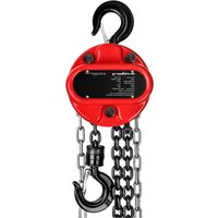
SBS-FZ 1000/3M - Hoists STEINBERG - Free user manual and instructions
Find the device manual for free SBS-FZ 1000/3M STEINBERG in PDF.


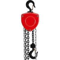
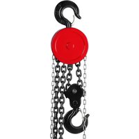
| Product type | Manual chain hoist |
| Brand | Steinberg |
| Model | SBS-FZ 1000/3M |
| Load capacity | 1 ton |
| Maximum lifting height | 3 meters |
| Minimum hook spacing | 265 mm |
| Required lifting force | 340 N |
| Chain link diameter | 6 mm |
| Number of load chains | 1 |
| Net weight | 8.6 kg |
| Chain | G80 |
| Operating ambient temperature | -10 °C to +50 °C |
| Material of parts | Metal |
| Power source | Manual (pull on hand chain) |
| Main functions | Manual lifting and lowering of loads |
| Brake | Automatic mechanical brake |
| Safety latch hook | Yes, with safety lock |
| Maintenance and cleaning | Regular cleaning, lubrication of chains and hooks |
| Recommended inspection frequency | Daily (visual), monthly (wear) |
| Spare parts and repairability | Friction plates replaceable after approximately 1500 cycles |
| Warranty | Follow conditions; unauthorized opening voids warranty |
| General information | Compliant with current safety standards |
Frequently Asked Questions - SBS-FZ 1000/3M STEINBERG
User questions about SBS-FZ 1000/3M STEINBERG
0 question about this device. Answer the ones you know or ask your own.
Ask a new question about this device
Download the instructions for your Hoists in PDF format for free! Find your manual SBS-FZ 1000/3M - STEINBERG and take your electronic device back in hand. On this page are published all the documents necessary for the use of your device. SBS-FZ 1000/3M by STEINBERG.
USER MANUAL SBS-FZ 1000/3M STEINBERG
DE
8
Rev. 28.06.2022
CE The product satisfies the relevant safety standards.
Operation manual must be reviewed
A
Note: Be aware of suspended loads!
Note! Never put your hands into hooks.
Note! Make sure bystanders remain in safe distance from the work place.
The original operation manual is in German. Other language versions are translations from German.
1. Before commencing work make sure to thoroughly read and understand this operation manual! All safety recommendations must be followed to avoid damages occurring as the result of using the equipment contrary to its intended use!
2. This operation manual must be retained for future reference. If the machine is transferred to third persons this operation manual must also be handed over with the machine.
3. If the machine is operated contrary to its intended use or in case of improper handling of the machine, liability for any resulting damage is excluded.
4. The machine can be operated by physically fit persons who are able to handle the machine and properly trained and who reviewed this operating manual and received training in occupational health and safety.
5. The machine is not designed to be handled by persons (including children) with limited mental and sensory functions or persons lacking relevant experience and/or knowledge unless they are supervised by a person responsible for their safety or they have received instructions on how to operate the machine.
6. Make sure the workplace is orderly and well lit. A messy or poorly lit workplace may lead to accidents. Try to anticipate what may happen, observe what is going on and use common sense when working with the device.
II. SAFE OPERATION PRINCIPLES / WARNINGS
- Review this operation manual and the safety recommendations prior to each use of the machine.
- Before each use make sure to check if parts are not worn or damaged to the extent where proper functioning of the machine impossible. This machine must not be operated if its parts are worn or damaged in a way that prevents proper operation (chain jumping, excessive noise, jamming chain, etc.).
- If the machine has been overloaded or subject to strong shock/vibrations, it must be inspected by a qualified service technician before commencing any work on the machine.
- This machine must not be operated if it is damaged, worn or if it does not work properly. If such condition occurs the machine must be handed over to an authorised service center for inspection and repair.
- Comprehensive periodic inspections of the machine must be carried out and worn/damaged parts must be replaced on an on-going basis.
- Use only original replacement parts, as recommended by the manufacturer.
- This machine may only be handled by persons properly trained in safety regulations and physically able to operate the machine.
- The machine must be lubricated on a regular basis.
- Do not use the machine if the hook latch is damaged in any way.
- Always check if the hook latches are properly closed.
- Do not attach the chain through screws put through the chain link.
- Do not overload the machine with a load exceeding the maximum admissible load.
- Do not put hands inside the hooks.
- Make sure that the load is stable and secured centrally under the hook. Do not pull the load.
- Do not use the machine with a shortened, clamped, looped or damaged chain.
- Do not hit the chain or hook.
- Do not put the hook through the chain link or attach the hook on the chain links.
- Always make sure that the load is properly hung on the hook and the hook latch is closed.
- Always check if all screw connections in the machine and/or its fixing are properly tightened.
- Do not walk or stay under a hanging load (and in its direct vicinity)
- Do not lift the load using the machine over people or animals.
- Do not lift people or animals using this machine.
- Always pay attention to the load.
- Do not leave a hanging load unattended.
- Avoid situations in which the load could swing.
- Third parties must be warned about operation of the machine and stay at a safe distance.
- Do not conduct mechanical or similar works (welding, cutting, etc.) on a hanging load.
-
After completion of work, the machine must be secured against unauthorised use.
-
The machine must be regularly controlled and its damaged or worn and torn parts must be replaced with new ones by an authorised service.
-
Load drop poses risk of injury or death.
- When working with the machine, use personal protection equipment (such as protective gloves). Always use proper tight-fitting work clothing.
- Attention: Risk of overheating the braking system during prolonged lowering of loads.
Failure to follow safety recommendations and instructions may result in serious injuries or death!
III. INTENDED USE OF THE MACHINE
The chain hoist is intended only for manual vertical lifting and lowering of loose loads at the work station. The weight of the load cannot exceed the admissible load bearing capacity when lifted. It can be used in factories, on agricultural farms, construction sites, for installation of devices as well as loading and unloading of goods. The chain hoist is very useful in open spaces and places without power supply. Do not use the machine in corrosive environments and environments with an explosive atmosphere.
The user is liable for any damage resulting from nonintended use of the device.
IV. TECHNICAL SPECIFICATIONS
| Product designation Chain hoist | ||||
| Model SBS-FZ 3000/3GM SBS-FZ 1000/12M SBS-FZ 2000/3M SBS-FZ 1000/3M | ||||
| Permissible payload [T] | 3 | 1 | 2 | 1 |
| Maximum lifting height [m] | 3 | 12 | 3 | 3 |
| Minimum distance between hooks [mm] | 450 | 265 | 405 | 265 |
| Force necessary for load lifting [N] | 343 | 340 | 314 | 340 |
| Chain link diameter [mm] | 6 | 6 | 6 | 6 |
| Number of chains | 2 | 1 | 2 | 1 |
| Weight [kg] | 20 | 23 | 12 | 8.6 |
| Chain | G80 | |||
| Ambient temperature [°C] | -10 + +50 | |||
V. BEFORE FIRST USE
Upon receipt of the goods, check the packaging for integrity and open it. If the packaging is damaged, please contact your transport company and distributor within 3 days and document the damages as detailed as possible. Do not turn the package upside down! When transporting the package, please ensure that it is kept horizontal and stable. The various items used for packaging (cardboard, plastic straps, polyurethane foam) should be conserved, so that the machine can be sent back to the service centre in the best condition in case of any problems!
VI. ASSEMBLING THE MACHINE
Location of the machine
Check if the machine is not damaged before installing it at the work station. Make sure that the load bearing structure on which the machine is installed is sufficiently strong to withstand the weight of the load and machine. Do not install the machine on a structure that cannot be verified in terms of load bearing capacity and strength. The user is responsible for the installation of the load bearing structure and for the load bearing structure itself.
When the machine is suspended on the load bearing structure, caution and all conditions for safe work must be ensured in order to avoid any threats connected with potential bodily injuries.
The user is responsible for preparation of the installation conditions as well as for the installation of the machine itself.
After installation, check if the hook is properly attached and if the latch is closed.
Always check brake operation for each load lifting. For this purpose, attach the sample load (ca. 10 % of admissible load) and lift it up and lower it several times to make sure that it will not slide down during lifting/lowering.
Always check the chain position and be mindful of twisting. Proper chain position means a single line of link connection points.
When the machine is installed at the work station, check the distance between the ground and the lower loop of the manual chain used to lift and lower the load. This distance should be from 500 mm to 1000 mm. If it is not, adjust the manual chain accordingly by lengthening or shortening is. To lengthen/shorten the manual chain, it must be disconnected. Bend the tips of the connecting link outwards and lengthen/shorten the chain by the appropriate length. Afterwards it must be reconnected by connecting the link again.
ACTION
Lifting / lowering
The hook must be set directly over the load so that the chain is not stretched. To hoist/lower a load, the manual chain used to lift and lower the load must be pulled. Hoisting/lowering can be stopped at any point.
In exceptional cases, in case of machines with great lifting height, the brake might heat up during uninterrupted fast load lowering. Always lower the load slowly, in intervals.
If the chain is jammed or in case of other irregularities in the machine's operation, stop the work immediately. Notify responsible, competent persons who can remove the load and perform activities restoring normal operation. Designate a safety zone around the machine and under the load to preclude access of unauthorised persons. The machine must be transferred to an authorised servicing centre.
When the locked load is being released on the winch, additional force may be required to release the friction between the brake components.
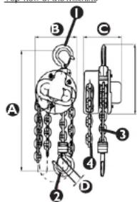
Top view of the machine
-
hook for load bearing structure hanging
-
hook for load hanging
-
load chain
-
control chain
Dimensions (mm):
| SBS FZ 3000/3GM SBS FZ 1000/12M SBS FZ 2000/3M SBS FZ 1000/3M | |||
| A 480 265 405 265 | |||
| B 160 145 142 145 | |||
| C 150 183 128 183 | |||
| D 32,5 27 | 37,3 | 27 | |
STORAGE
The machine must always be stored without load. Remove dirt. The chain, hook pins and hook latch pins must be lubricated. Hang in a dry place. Follow the instructions provided in this manual before the next use of the chain hoist.
REVIEWS
Before being used, the new or repaired machine must be checked by qualified technical personnel who have knowledge and experience within the scope of operation and maintenance of this type of machine.
The machine must be checked regularly by means of visual control of the machine's condition, before, during and after use. The check must be performed by the machine's operators. Any irregularities in machine operation as well as any damage must be reported to the proper technical personnel. Do not use the machine if damage or any irregularities in its operation were found.
INSPECTION AND MAINTENANCE DATES
• PRELIMINARY INSPECTION: Before first use. All new or repaired machines must be checked by a qualified and competent person to ensure the machine meets the requirements of this operating manual.
• DAILY INSPECTIONS
- Check brake operation.
- Check the chains - cleanliness, lubrication, twisting.
- Check the hooks: level of wear and tear, damage, enlargement of the hook slit, shank bend or hook deviation
• REGULAR INSPECTIONS (recommended as monthly):
- Check chain wear and tear.
- Check the wear and tear of the hooks: level of wear and tear, damage, enlargement of the hook slit, shank bond or hook deviation.
- Check fastening of the hooks.
- Clean and lubricate the chains.
POSSIBLE HAZARDS DURING USE
The hazards that can occur during use of the machine are mechanical hazards. The mechanical hazard occurs in situations in which injuries can result from mechanical impact of various elements, e.g. machine parts, tools, etc. on people.
The basic mechanical hazards include squeezing, crushing, cutting, pulling in or catching; impact, puncture; abrasion; as well as slipping and stumbling.
These hazards can occur both during normal machine operation and as a result of irregularities in machine operation. These irregularities might result in machine failure.
The mechanical hazards can result from: moving machines, transported loads, moving elements, sharp/rough elements, dropping elements/loads, slippery uneven surfaces, limited space, location of the work station in relation to the ground (work at heights and in depths).
VII. CLEANING AND MAINTENANCE
The chain hoist must be cleaned regularly. After completion of work, remove all dirt from the chains and the machine itself. The chains, hooks, hinges and hook latches must be regularly lubricated with grease. When the load chain is rusted, the rust must be removed and the chain greased. If rust cannot be removed, the load chain must be replaced. All and any hoist maintenance and inspection activities must be carried out by a trained and qualified employee. They cannot be conducted by a person without proper experience and knowledge.
NOTE
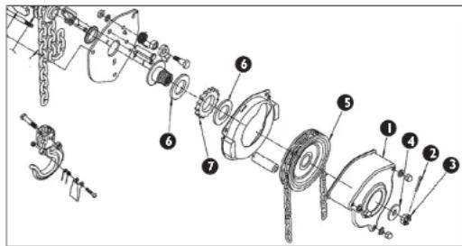
After 5 months of using the chain hoist (approximately if the hoist will be used more than 1500 times - 10 times daily), the friction plates should be replaced:
I. Unscrew the cover I.
2. Remove the split pin 2.
3. Unscrew the nut 3, take out the washer 4.
4. Unscrew the chain wheel 5.
5. Take out the friction plate 6
5. Take out the friction plate 6.
6. Remove the market wheel 7.
6. Remove the Ratchet wheel 7.
7. Take out the friction plate 6.
8. Reassemble in reverse order using new friction plates.
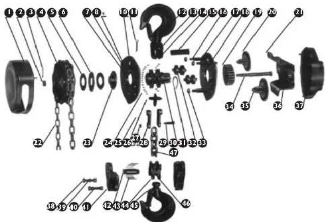
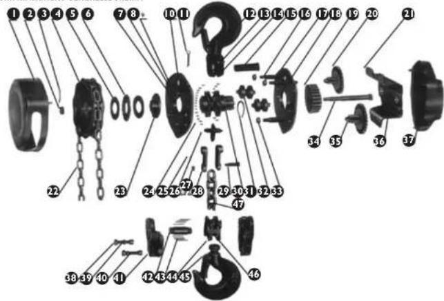
VIII. GENERAL MACHINE DIAGRAM
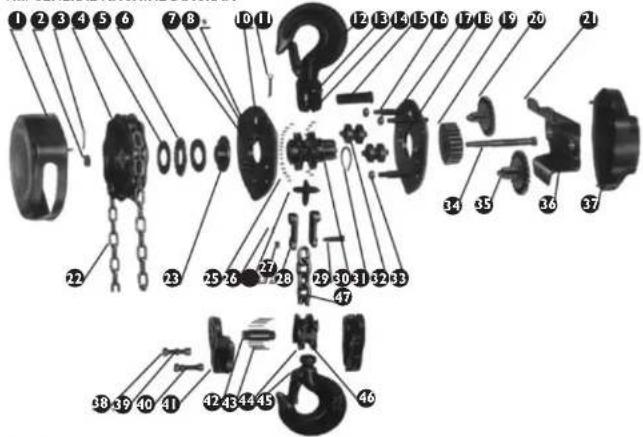
EN
| 1 | Wheel housing | 17 | Plate right side | 33 | Nut |
| 2 | Nut | 18 | Bearing load ring | 34 | Clutch |
| 3 | Arbor | 19 | Spindle transmission | 35 | Rack |
| 4 | Wheel | 20 | Transmission | 36 | Bearing load ring |
| 5 | Hub washer | 21 | Bent plate | 37 | Lid |
| 6 | Ratchet wheel | 22 | Chain | 38 | Nut |
| 7 | Ratchet | 23 | Break | 39 | Washers |
| 8 | Ratchet arbor | 24 | Roller | 40 | Screws |
| 9 | Plate left side | 25 | Arbor | 41 | Lower clamp |
| 10 | Spring | 26 | Stripper | 42 | Wheel shaft |
| 11 | Arbor | 27 | Nut | 43 | Needle |
| 12 | Rivet | 28 | Hub suspension | 44 | Hook |
| 13 | Rivet | 29 | Hub arbor | 45 | Latch |
| 14 | Upper clamp | 30 | Chain gear wheel | 46 | Roller |
| 15 | Shaft arbor | 31 | Ring | 47 | Load chain |
| 16 | Support | 32 | Roller |
IX. REGULAR CONTROL OF THE MACHINE
Regularly check the machine for signs of damage. If it should be damaged, please stop using it immediately and contact your customer service to solve the problem.
What to do in case of a problem?
Please contact your customer service and prepare following information:
- Invoice number and serial number (the latter is to be found on the technical plate on the machine).
+ if relevant, a picture of the damaged, broken or defective part.
It will be easier for your customer service clerk to determine the source of the problem if you give a detailed and precise description of the matter.
The more detailed your information, the better customer service will be able to solve your problem rapidly and efficiently! CAUTION: Never open the machine without the authorization of your customer service. This can lead to a loss of warranty! The machine does not contain any substances harmful to one's health, its parts are made of metal. After withdrawal from service, the machine must be transferred to a scrap yard. Observe the environmental protection regulations of the given country.
INSTRUKCIA OBSŁUGI
I. ZALECENIA ODNOŚNIE BEZPIECZEŃSTWA
IX. OGÓLNY SCHEMAT MASZYNY
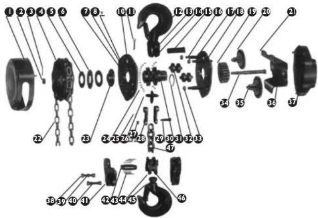
VIII. PŘEHLEDNÉ SCHÉMA ZAŘÍZENÍ
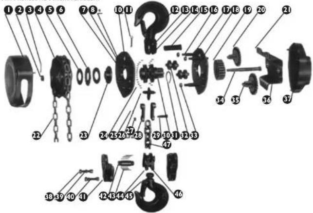
IX. SCHÉMA D'ENSEMBLE DE LA MACHINE
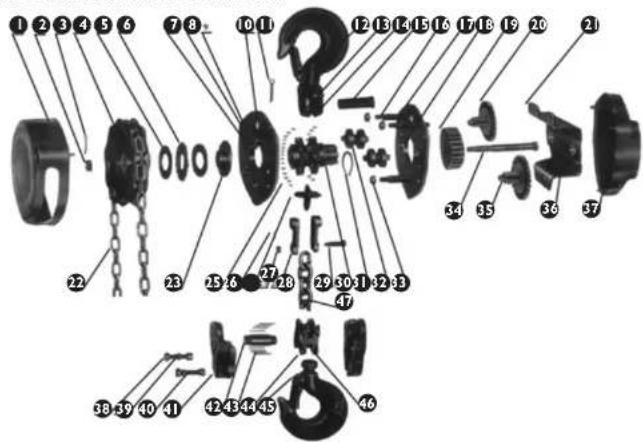
XI. SCHEMA GENERALE DELLA MACCHINA
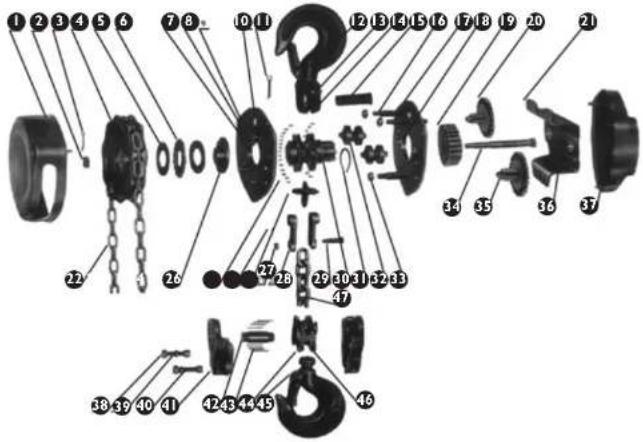
XI. ESQUEMA GENERAL DE LA MÁQUINA
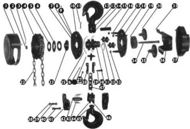
HU
VIII. A GÉP ÁLTALÁNOS ÁBRAJA
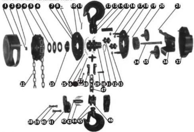
VIII. MASKINENS GENERELLE SKEMA
DA
| 1 | Hjulhus | 17 | Højre side af pladen | 33 | Matrik |
| 2 | Matrik | 18 | Lejering | 34 | Kobling |
| 3 | Stift | 19 | Spindelgear | 35 | Tandhjul |
| 4 | Hjul | 20 | Gear | 36 | Lejering |
| 5 | Hjulnav | 21 | Bukket plade | 37 | Låg |
| 6 | Spærnchjul | 22 | Kæde | 38 | Matrik |
| 7 | Spærro | 23 | Bromsc | 39 | Underlagsskiver |
| 8 | Spærrostift | 24 | Rulle | 40 | Skruer |
| 9 | Vonstro side af pladen | 25 | Stift | 41 | Nodro ophaeng |
| 10 | Fjeder | 26 | Skubber | 42 | Hjulaksel |
| 11 | Stift | 27 | Matrik | 43 | Nål |
| 12 | Nitte | 28 | Navophaeng | 44 | Krog |
| 13 | Nitte | 29 | Navstift | 45 | Smaeklås |
| 14 | Ovre ophaeng | 30 | Kædetanchjul | 46 | Rulle |
| 15 | Akselstift | 31 | Ring | 47 | Lastkaede |
| 16 | Understatte | 32 | Rulle |
IX. REGELMÆSSIG INSPEKTION AF APPARATET
KONTROLLER REGELMÆSSIGT APPARATETS KOMPONENTER FOR SKADER Hvis komponenterne or beskadigede, skal du kontakte din forhandler for at reparere dem.
VIII. LAITTEENYLEISKAAVIO
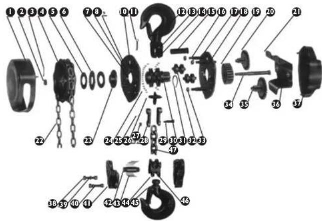
VIII. MASKINENS GENERELLE SKEMA
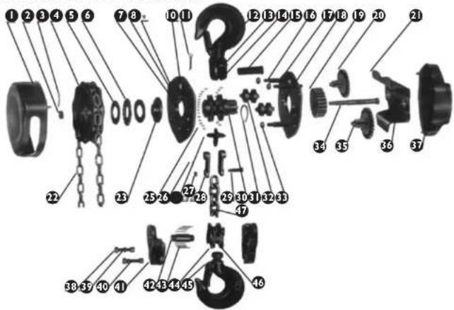
| 1 | Hjulhus | 17 | Højre side af pladen | 35 | Matrik |
| 2 | Matrik 18 Lejering 34 Kobling | ||||
| 3 | Stift 19 Spindelgear 35 Tandhjul | ||||
| 4 | Hjul 20 Gear | 36 Lejering | |||
| 5 | Hjulnav 21 Bukket plade 37 Låg | ||||
| 6 | Spazmehjul | 22 | Køzde | 38 | Matrik |
| 7 | Spazirre | 23 | Bremse | 39 | Underlagssakiver |
| 8 | Spazmestift | 24 Rulle | 40 Skruer | ||
| 9 | Verstre side af pladen | 25 | Sift | 41 | Nedre ophuzng |
| 10 | Fjedler | 26 | Skubber | 42 | Hjulaksel |
| 11 | Sift 27 Matrik | 43 Nål | |||
| 12 | Nitte | 28 Navophaeng | 44 Krog | ||
| 13 | Nitte | 29 Navsüft | 45 Smaeklås | ||
| 14 | Övre ophaeng | 30 | Kædletandhjul | 46 | Rulle |
| 15 | Akselstift | 31 Ring | 47 Lastkædo | ||
| 16 | Understartte | 32 Rulle | |||
IX. REGELMAESSIG INSPEKTION AF APPARATET
KONTROLLER REGELMESSIGT APPARATETS KOMPONENTER FOR SKADER Hvis komponenterne er beskadigede, skal du kontakte din forhandler for at reparere dem.
DATOER FOR INSPEKSJONER OG VEDLIKEHOLD
• DAGLIG VEDLIKEHOLD
• Kontroller bremsens funksjon.
- Kontroller kjettingene – renhet, smøring, vridninger.
VIII. GENERELT DIAGRAM OVER MASKINEN
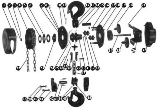
| 1 | Hjulhus | 37 | Høyre side av platen | 53 | Mutter |
| 2 | Mutter 18 Lagenets stettering 34 Kopling | ||||
| 3 | Stift 19 Spindolgir 35 Tannhjul | ||||
| 4 | Hjul | 20 | transmisjon | 96 | Lagenets stettering |
| 5 | Navskive 21 Boyd plate 37 Lokk | ||||
| 6 | Spørrehjul | 22 | Kjetting | 38 | Mutter |
| 7 | Sperrer | 23 Bremse | 39 Skiver | ||
| 8 | Spierrestift | 24 Aksel | 40 Skruer | ||
| 9 | Platens venstre side | 25 | Stift | 41 | Nedre feste |
| 10 | Fjør | 26 | Stater | 42 | Hjulaksel |
| 11 | Slift 27 Mutter | 43 Nål | |||
| 12 | Nagle | 28 Navoppheng | 44 Krok | ||
| 13 | Nagle | 29 Navstift | 45 Lås | ||
| 14 | Dvre feste | 30 | Kjettingens tannhjul | 46 | Aksel |
| 15 | Akselskaft | 31 Ring | 47 Beerekjøtting | ||
| 16 | Søtta | 32 Aksel | |||
IX. REGELMESSIG KONTROLL AV MASKINEN
VIII.ALLMÄNT MASKINSCHEMA
- gancho para pendurar na estrutura de suporte
- gancho para pendurar a carga
- corrente de carga
- corrente de controla
Dimensões (mm):
| SBS-FZ 3000/3GM SBS-FZ 1000/12M SBS-FZ 2000/3M SBS-FZ 1000/3M | ||||
| A | 460 | 265 | 405 | 265 |
| B | 160 | 145 | 142 | 145 |
| C | 150 | 183 | 128 | 183 |
| D | 52.5 | 27 | 37.3 | 27 |
ARMAZENAMENTO
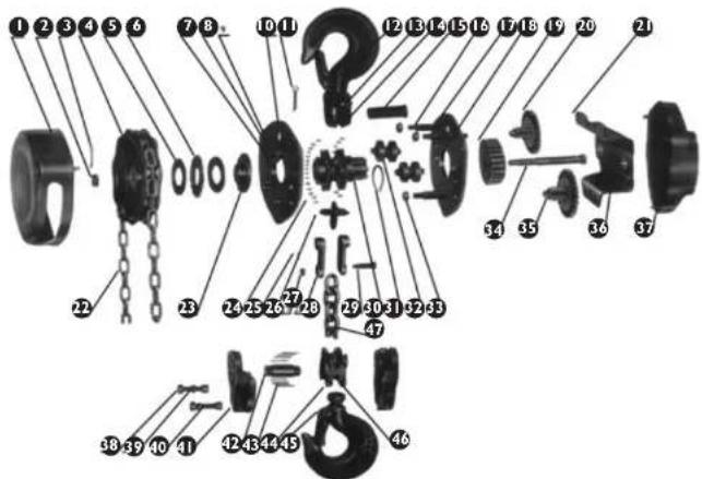
VIII. ESQUEMA GERAL DA MÁQUINA
NAMPLATE TRANSLATIONS
| 1 Product name Chain Hoist | |
| 2 Model | |
| 3 Max. lifting capacity | |
| 4 Max. lifting height | |
| 5 Weight | |
| 6 Serial number | |
| 7 Date of production | |
| 9 Manufacturer; expondo Polska sp. z o.o. sp. k.ul. Nowy Kislelin-Innowacyjna 7, 66-002 Zielona Góra | Poland, EU |
| 1 | 2 | 3 | 4 | |
| DE | Produktname | Modell | Max. fragfähigkeit | Max. hushöhle |
| FN | Product Name | Model | Max. lifting capacity | Max. lifting height |
| PL | Nazwa produktu | Model | Maksymalna-ladowność | Maksymalna wysokość podnoszenia |
| CZ | Název výrobiu | Model | Povolená únosnost | Maximalni výtka zvedání |
| FR | Nom du produit | Modèle | Max. charge admissible | Hauteur de levage maximale |
| IT | Nome del prodotto | Modello | Max. carica consentio | Allezza di sollevamento maxima |
| FS | Nombre del producto | Modelo | Carga máxima permitida | Max. altura de elevación |
| 5 | 6 | 7 | 8 | |
| DE | Gewicht | Ordnungsnummer | Produktionsjahr | Hersteller |
| FN | Weight | Serial No. | Date of production | Manufacturer |
| PL | Waga | Numero seri | Rok produkcji | Produzent |
| CZ | Hmotnost | Sériové číslo | Rok výroby | Výrobce |
| FR | Poids | Numero de serie | Année de production | Fabricant |
| IT | Peso | Numero di serie | Anno di produzione | Produzione |
| ES | Peso | Numero de serie | Año de producción | Fabricante |

DE | EN | PL | FR | IT | ES | CZ

EG-Konformitätserklärung | EU Declaration of conformity | Deklaracja zgodności WE | Déclaration UE de conformité | Dichiarazione di conformità UE | Declaración UE de conformidad | Prohläšeni o shodě ES, 2019/25-03/86
For the disposal of the device please consider and act according to the national and local rules and regulations.
CONTACT
expondo Polska sp. z o.o. sp. k.
- SAFE OPERATION PRINCIPLES / WARNINGS
- INTENDED USE OF THE MACHINE
- BEFORE FIRST USE
- ASSEMBLING THE MACHINE
- Location of the machine
- ACTION
- Lifting / lowering
- STORAGE
- REVIEWS
- INSPECTION AND MAINTENANCE DATES
- POSSIBLE HAZARDS DURING USE
- CLEANING AND MAINTENANCE
- NOTE
- REGULAR CONTROL OF THE MACHINE
- ZALECENIA ODNOŚNIE BEZPIECZEŃSTWA
- REGELMÆSSIG INSPEKTION AF APPARATET
- REGELMAESSIG INSPEKTION AF APPARATET
- DATOER FOR INSPEKSJONER OG VEDLIKEHOLD
- REGELMESSIG KONTROLL AV MASKINEN
- ARMAZENAMENTO
- NAMPLATE TRANSLATIONS
- DE | EN | PL | FR | IT | ES | CZ
- CONTACT
Brand : STEINBERG
Model : SBS-FZ 1000/3M
Category : Hoists