STAR_ATFE_11 - Office Fromm & Starck - Free user manual and instructions
Find the device manual for free STAR_ATFE_11 Fromm & Starck in PDF.

| Product type | Electric height-adjustable desk |
| Model | STAR_ATFE_11 |
| Brand | Fromm & Starck |
| Supply voltage | 230 V~ / 50 Hz |
| Rated power | 450 W |
| Maximum load capacity | 150 kg |
| Height adjustment range | 600 – 1250 mm |
| Adjustment speed | 38 mm/s |
| Frame dimensions (left) | 1100 x 680 x 600 mm |
| Frame dimensions (right) | 900 x 320 x 600 mm |
| Weight | 46 kg |
| Duty cycle | 2 min operation / 18 min pause |
| Number of motors | 3 |
| Height memory | 3 positions |
| Anti-collision function | Yes, 4 sensitivity levels (A0-A3) |
| Position reminder alarm | Yes, adjustable (default 45 min) |
| Control panel | Digital with LED display |
| Power supply | Mains |
| Usage | Indoor only |
| Operating temperature | 0 – 40 °C |
| Max. relative humidity | 85 % |
| Main material | Steel |
| Certifications | CE (compliant with safety standards) |
| Recycling | Compliant with WEEE directive |
Frequently Asked Questions - STAR_ATFE_11 Fromm & Starck
User questions about STAR_ATFE_11 Fromm & Starck
0 question about this device. Answer the ones you know or ask your own.
Ask a new question about this device
Download the instructions for your Office in PDF format for free! Find your manual STAR_ATFE_11 - Fromm & Starck and take your electronic device back in hand. On this page are published all the documents necessary for the use of your device. STAR_ATFE_11 by Fromm & Starck.
USER MANUAL STAR_ATFE_11 Fromm & Starck

natural_image
Technical line drawing of a structural beam with two downward arrows indicating load or compression (no text or symbols present)natural_image
Diagram of a mechanical assembly with two curved arrows indicating motion or force direction (no text or symbols)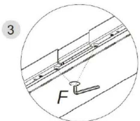
*CAUTION: After every 2 minutes of continuous motor operation, allow the unit to cool down and remain idle for at least 18 minutes.
1. General Description
The instruction manual is intended to assist in safe and reliable use. The product is designed and manufactured strictly according to technical specifications using the latest technology and components and maintaining the highest quality standards.
PLEASE CAREFULLY READ AND UNDERSTAND THIS INSTRUCTION MANUAL BEFORE OPERATION,
To ensure long and reliable operation of the unit, make sure to operate and maintain it properly in accordance with the guidelines in this instruction manual. The technical data and specifications contained in this instruction manual are up to date. The manufacturer reserves the right to make changes in order to improve the quality. Taking the technical progress and the possibility of reducing noise into account, the unit
is designed and built in such a way so that risks resulting from noise emissions are reduced to the lowest possible level.
Explanation of symbols
 | The product complies with applicable safety standards. |
 | Please read the instructions before use. |
 | Recyclable product. |
 | CAUTION! or WARNING! or REMINDER! describing a situation.(general warning sign). |
 | CAUTION! Warning of electric shock! |
 | For indoor use only. |

CAUTION! The illustrations in this instruction manual are for reference only and may differ from the actual product in some details.
The original instruction manual is in the German language version. Other language versions are translations from German.
2. Safety of use

CAUTION! Read all safety warnings and all instructions. Failure to follow the warnings and instructions may result in electric shock, fire and/or severe personal injury or death.
The term "unit" or "product" in the warnings and in the description of the instructions refers to the
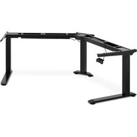
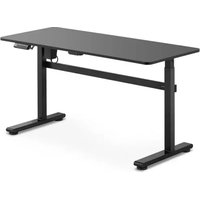
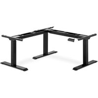
Corner electric sit stand desk frame
2.1. Electrical safety
a) The plug of this unit must fit into the outlet. Do not modify the plug in any way. Original plugs and matching outlets reduce the risk of electric shock.
b) Avoid touching grounded parts, such as pipes, heaters, ovens, and refrigerators. There is an increased risk of electric shock if your body is grounded and touches the unit exposed to direct rain, wet pavement, and operation in a humid environment. If water enters the unit, there is an increased risk of damage to the unit and electric shock.
c) Do not touch the unit with wet or damp hands.
d) Do not use the cord in an unintended manner. Never use it to carry the unit or to pull the plug out of the socket. Keep the cord away from heat sources, oil, sharp edges or moving parts. Damaged or tangled cords increase the risk of electric shock.
e) If you cannot avoid using the unit in a wet environment, use a residual current unit (RCD). Using an RCD reduces the risk of electric shock.
f) Do not use the unit if the power cord is damaged or shows signs of wear. A damaged power cord should be replaced by a qualified electrician or the manufacturer's service department.
g) To avoid electric shock, do not immerse the cable, plug, or unit itself in water or other liquid. Do not use the unit on wet surfaces.
h) CAUTION - THREAT TO LIFE! When cleaning or using the unit, never immerse it in water or other liquids.
i) Do not use the unit in rooms with very high humidity / in the immediate vicinity of water tanks!
2.2. Safety in the workplace
a) Keep the work area tidy and well lit. Disorder or poor lighting can lead to accidents. Be foresighted, watch what you are doing and use common sense when using the unit.
b) Do not use the unit in an explosive area, for example in the presence of flammable liquids, gases or dust.
EN
c) If you find any damage or irregularities in the operation of the unit, immediately turn it off and report it to an authorized person.
d) If you have any doubts as to whether the unit is working properly or if it is damaged, contact the manufacturer's service department.
e) Only the manufacturer's service department can repair the unit. Do not carry out repairs yourself!
f) In case of open flames or fire, use only dry powder or snow (CO2) fire extinguishers to extinguish the live equipment.
g) Keep these instructions for use for future reference. If the unit is to be passed on to a third party, the operating instructions must also be handed over together with the unit.
h) Keep the packaging and small assembly parts out of the reach of children.
i) When using this unit together with other units, also follow the other instructions for use.

Please note! Keep children and other bystanders safe while operating the unit.
2.3. Personal safety
a) The unit is not intended to be used by persons (including children) with reduced mental, sensory or intellectual functions or persons who lack experience and/or knowledge unless they are supervised or have been instructed by a person responsible for their safety on how to operate the unit.
b) Do not wear loose clothing or jewelry. Keep hair, clothing, and gloves away from moving parts. Loose clothing, jewelry, or long hair can be caught in moving parts.
c) Before switching the unit on, remove any regulating tools or keys. Any tools or keys left in the rotating part of the unit may cause injury.
d) Pressurized air can cause serious injuries.
e) Eye, ear, and respiratory protection is recommended.
f) The unit is not a toy. Children should be watched to ensure that they do not play with the unit.
g) Do not place your hands or any objects inside the running unit!
2.4. Safe use of the unit
a) Unplug the unit before making adjustments, changing accessories, or putting it away. This precaution reduces the risk of accidental start-up.
EN
b) Keep unused equipment out of the reach of children and out of the reach of anyone unfamiliar with the unit or this instruction manual. These units is dangerous in the hands of inexperienced users.
c) Keep the unit in good working condition. Check before each use for general damage or damage to moving parts (cracks in parts and components or any other condition that may affect the safe operation of the unit). If damaged, have the unit repaired before use.
d) Repairs and maintenance should be carried out by qualified personnel using only original spare parts. This will ensure the safety of use.
e) To ensure the designed operational integrity of the unit, do not remove factory-installed covers or loosen screws.
f) When transporting or moving the unit from storage to the place of use, observe the health and safety rules for manual handling applicable in the country where the unit is used.
g) Avoid situations in which the machine stops under heavy loads during operation. This can cause overheating of the drive elements and consequent damage to the equipment.
h) Do not touch any moving parts or accessories unless the unit is unplugged.
i) Do not move, shift, or rotate the machine while in operation.
j) Do not leave the unit switched on unattended.
k) Clean the unit regularly to prevent permanent dirt build-up.
I) The unit is not a toy. Cleaning and maintenance must not be performed by children without adult supervision.
m) Do not start up an empty machine.
n) Do not tamper with the unit to alter its performance or design.
o) Keep the unit away from sources of fire and heat.
p) Do not overload the unit.
q) Inappropriate use of the product, such as sitting on the worktop, may result in product damage and/or personal injury. Sitting on the desk top is prohibited to prevent serious injury.
r) Do not move or lie under the desk structure during adjustment. Do not sit or stand on the desk frame. Use extreme caution when making adjustments.
s) Check regularly whether the adjustment mechanism of the desk is working properly and remove any obstacles which may block the smooth adjustment of the desk.
t) Make sure that cables, connections and plugs do not interfere with the use of the product.
u) When adjusting the height of the desk, make sure that the lead wires are of sufficient length. The cables and connections that are too short may hinder height adjustment or damage other equipment.
v) Do not use the product if the control box makes noise or emits an unpleasant odor. Do not modify the power supply or the control box by yourself.

CAUTION! Although the product has been designed to be safe, with adequate safeguards, and despite the additional safety features provided to the user, there is still a slight risk of accident or injury when handling the unit. You are advised to use caution and common sense when using this product.
3. Rules of use
The product is designed to support and adjust the height of the desk top. The user is responsible for any damage resulting from misuse.
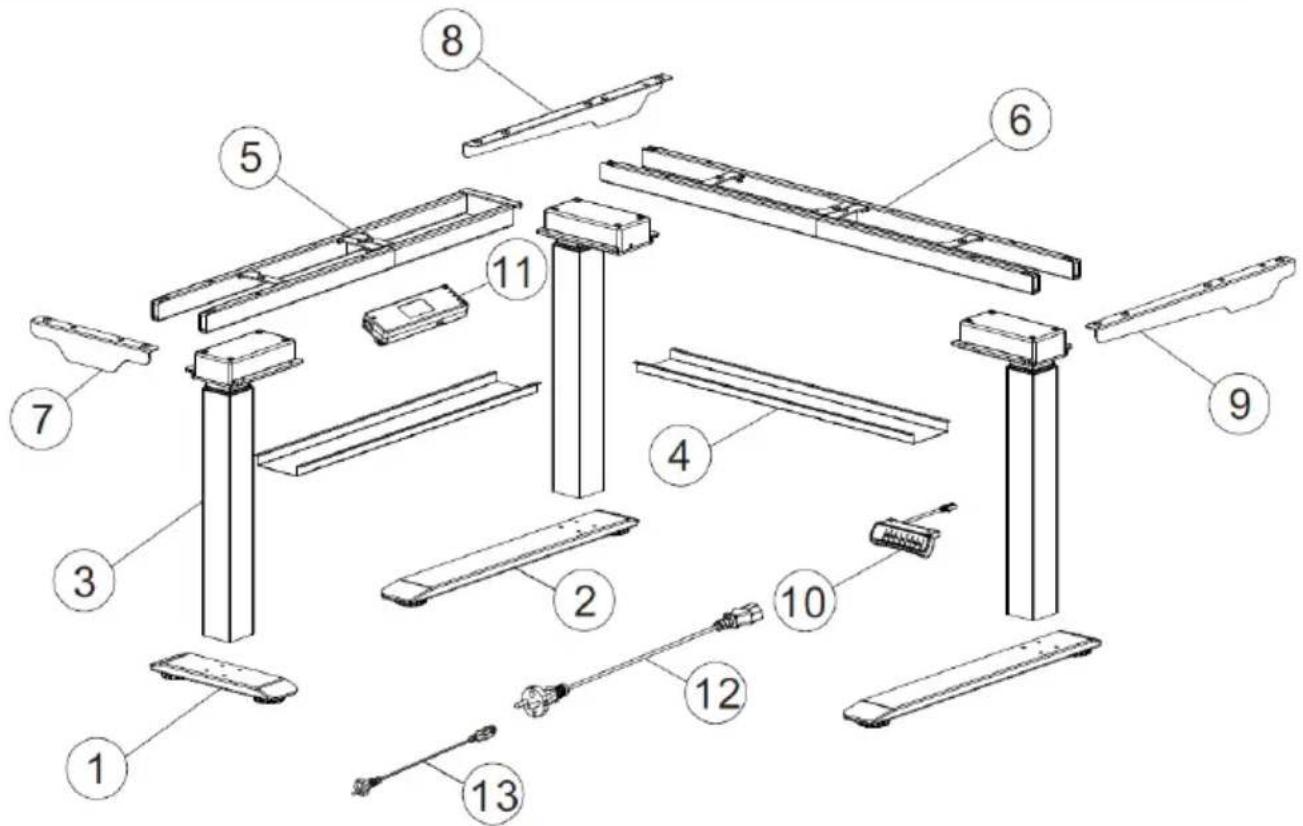
3.1. Description
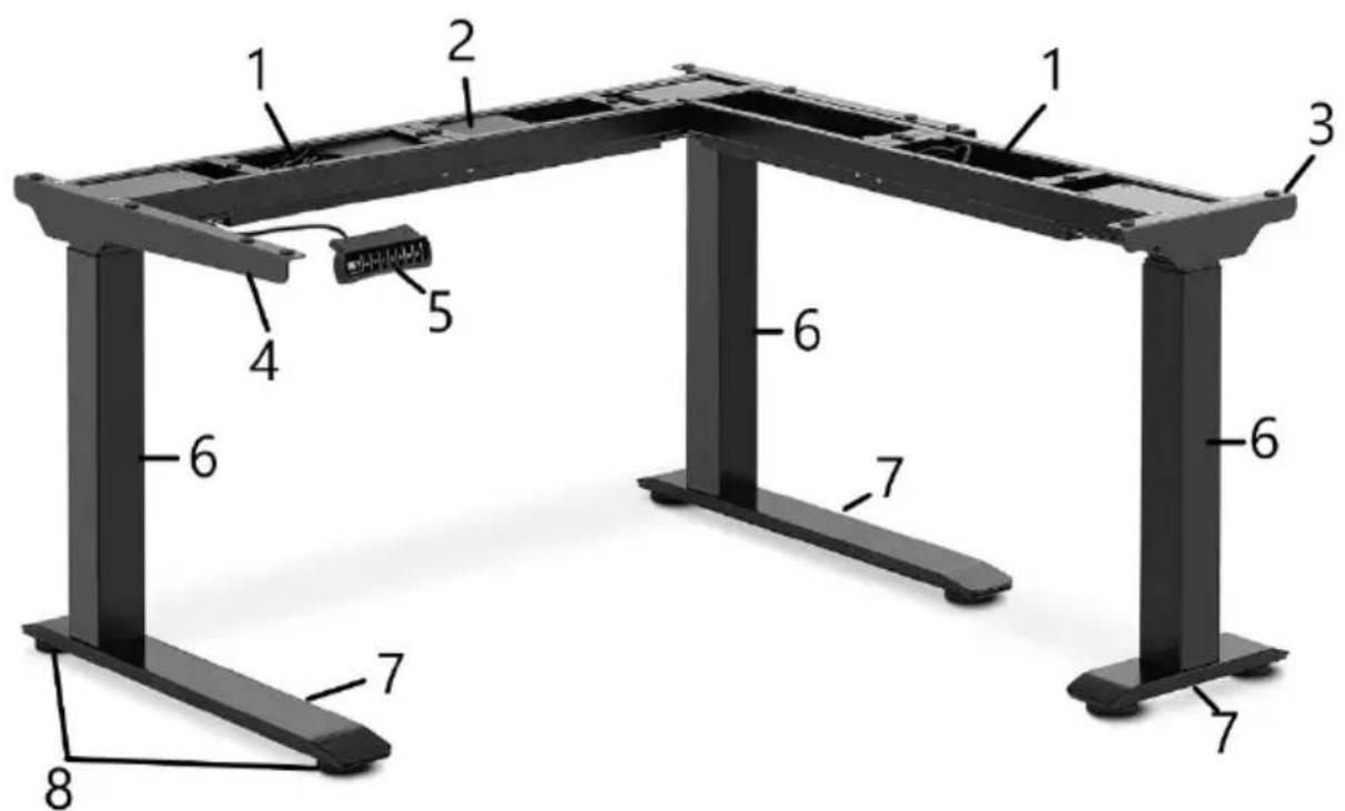
- Cable duct
- Control box
- Right bracket
- Left bracket
- Control panel
- Lifting column
- Base
8. Feet
Control panel description

-
Control panel power cord
-
Mounting holes
- Display
- Button which raises the desk up
- Button lowering the desk down
- Position 1, first height position saved by the user
- Position 2, second height position saved by the user
- Position 3, the third height position you have saved
- Button for storing height positions in the memory
- Alarm button - reminds you to change your desk position
3.2. Preparation for operation
POSITIONING OF THE UNIT
The ambient temperature should be between 0 and 40^ and the relative humidity should not exceed 85% . Place the unit in a way that ensures good air circulation.
Keep the unit away from any hot surfaces. Always operate the unit on a level,
EN
stable, clean, fireproof and dry surface and out of the reach of children and persons of impaired mental, sensory and intellectual functions. Place the unit in such a way that the mains plug can be reached at any time. Ensure that the power supply to the unit corresponds to that specified on the identification plate!
ASSEMBLY OF THE UNIT
Parts list
| No. | Drawing | Quantity |
| A | 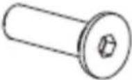 | 6 |
| B | 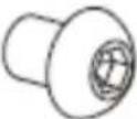 | 8 |
| C |  | 12 |
| D | 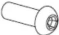 | 16 |
| E | 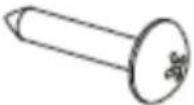 | 24 |
| F | 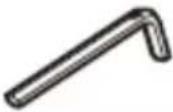 | 1 |
| No. | Drawing | Description of the | Quantity |
| 1 | 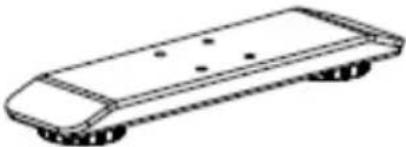 | Short base | 1 |
| 2 | 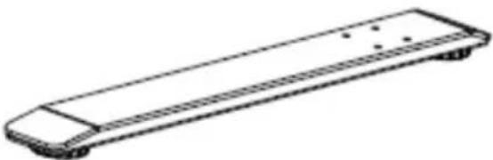 | Long base | 2 |
EN
| 3 | 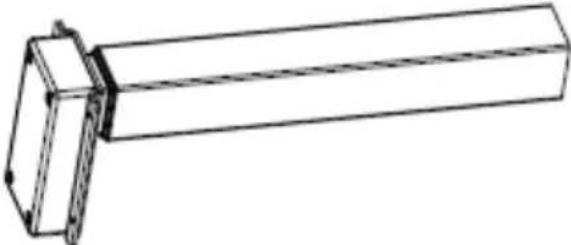 | Lifting column | 3 |
| 4 | 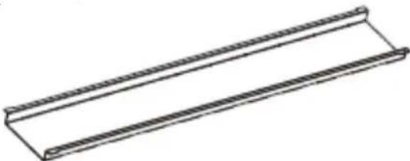 | cable tray | 2 |
| 5 | 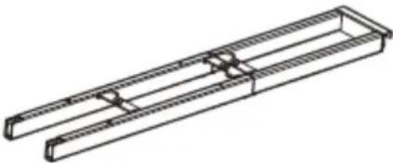 | Side beam | 1 |
| 6 | 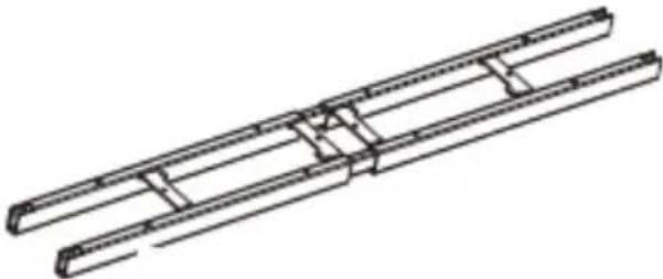 | Support beam | 1 |
| 7 | 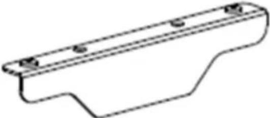 | Left short bracket | 1 |
| 8 | 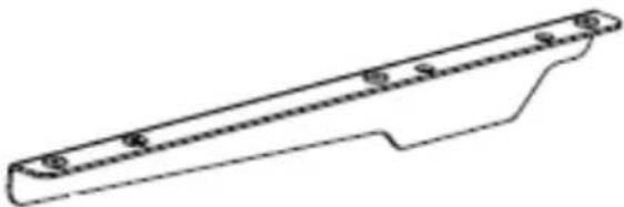 | Left long bracket | 1 |
| 9 | 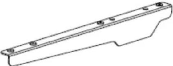 | Right bracket | 1 |
EN
| 10 | 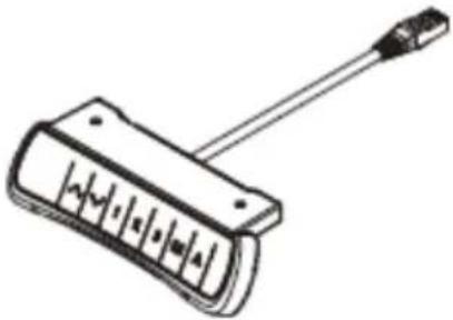 | Control panel | 1 |
| 11 | 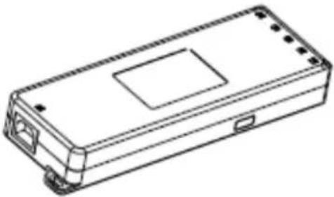 | Control box | 1 |
| 12 | 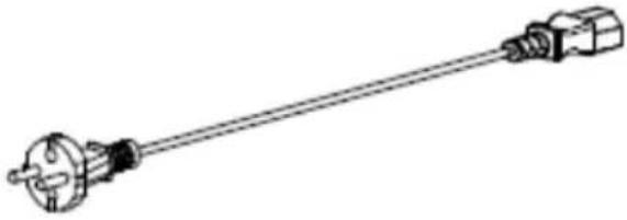 | Power cord | 1 |
| 13 | 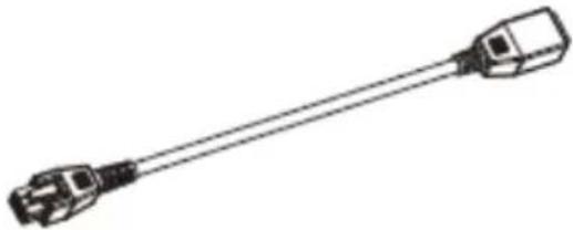 | Connector cable | 1 |
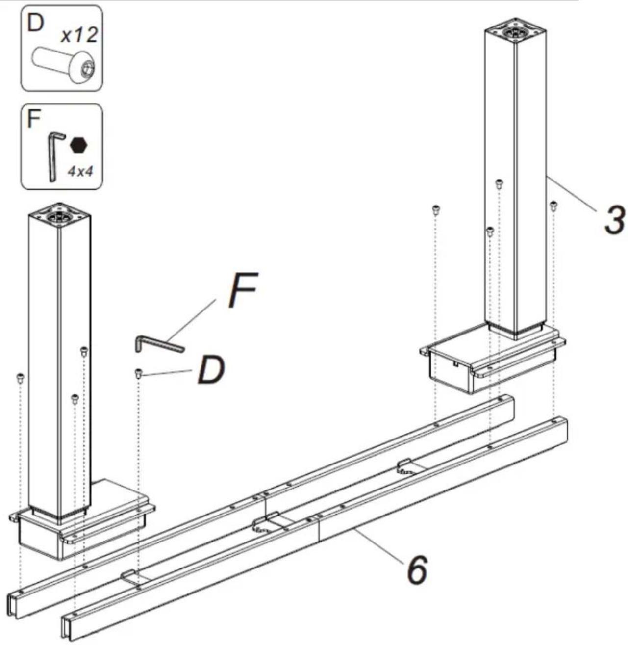
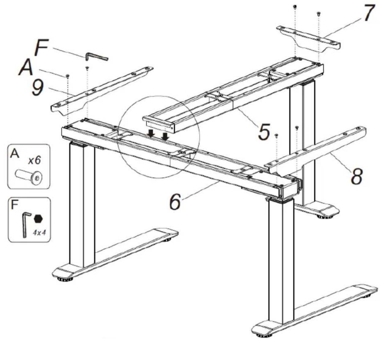
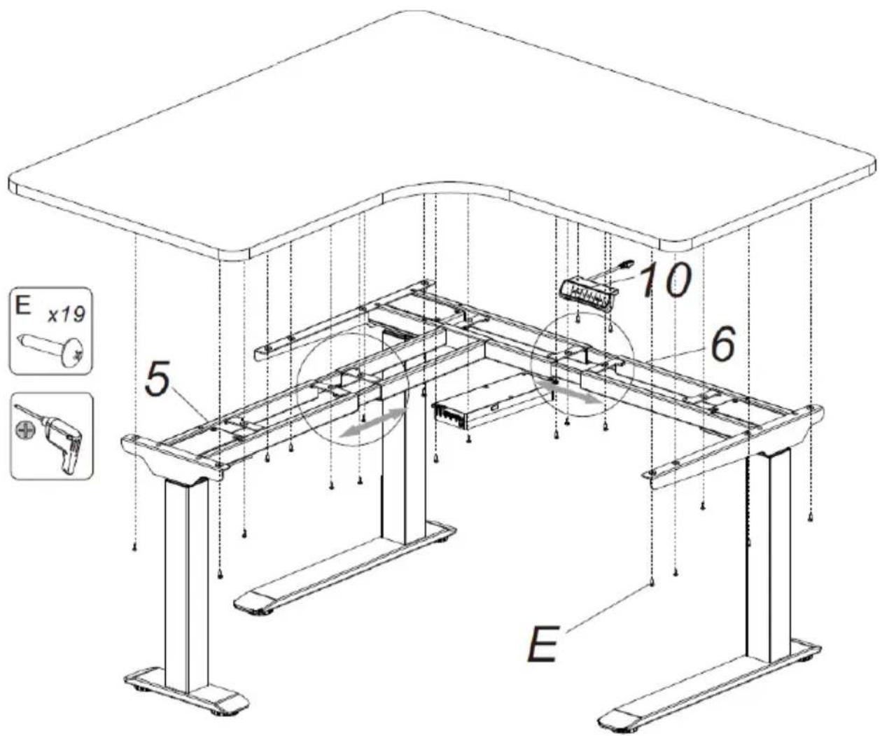
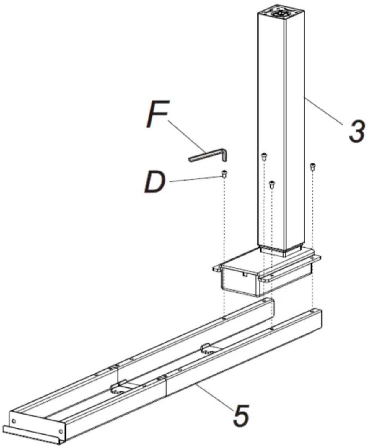
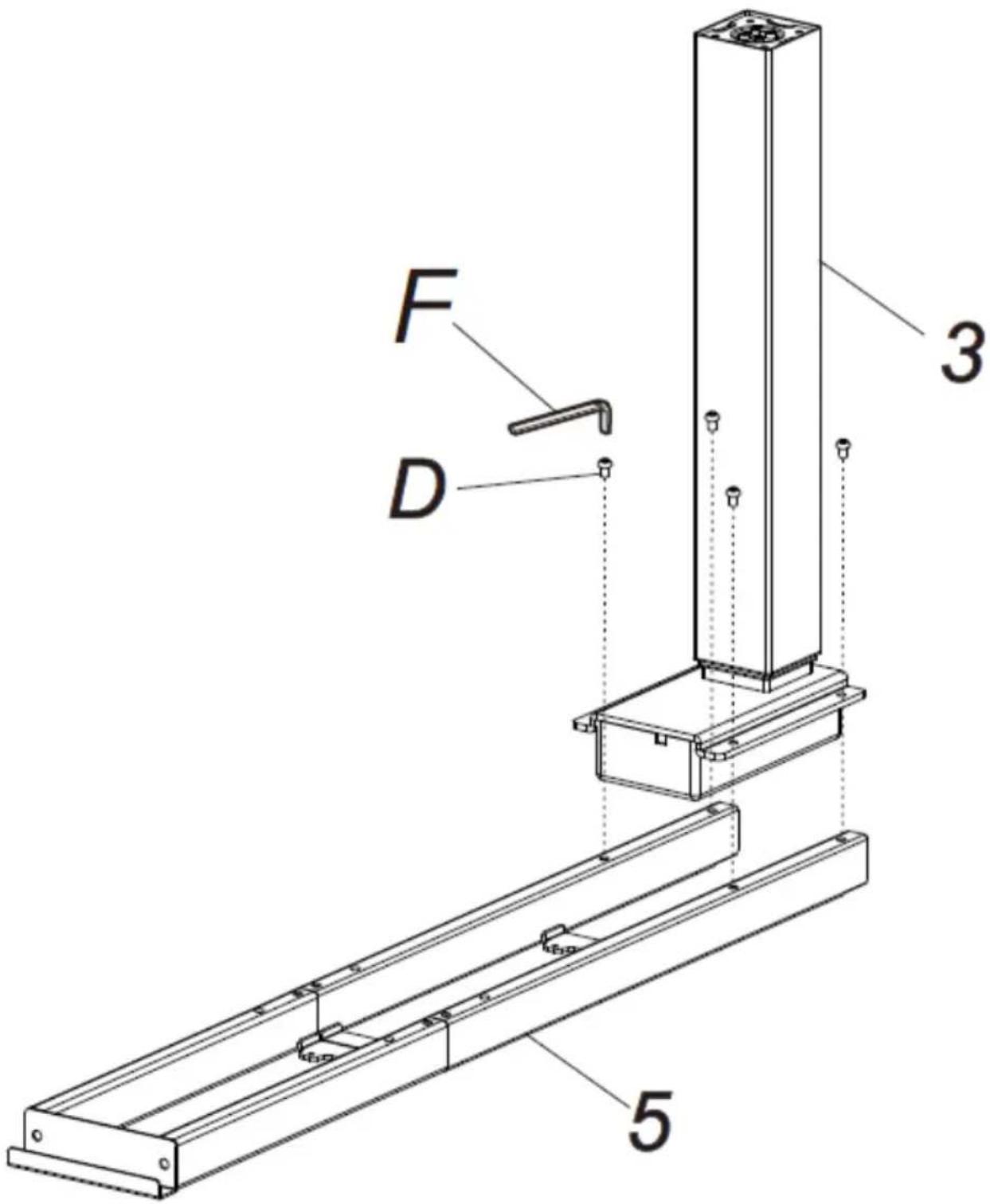
Caution: The numbering and markings in the following figures refer to the numbering and symbols assigned to the parts in the parts list.
- Bolt the lifting columns (2) to the support beam (6) and to the side beam (5) using hex socket screws (D).
EN

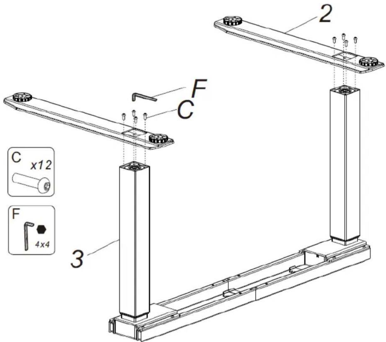
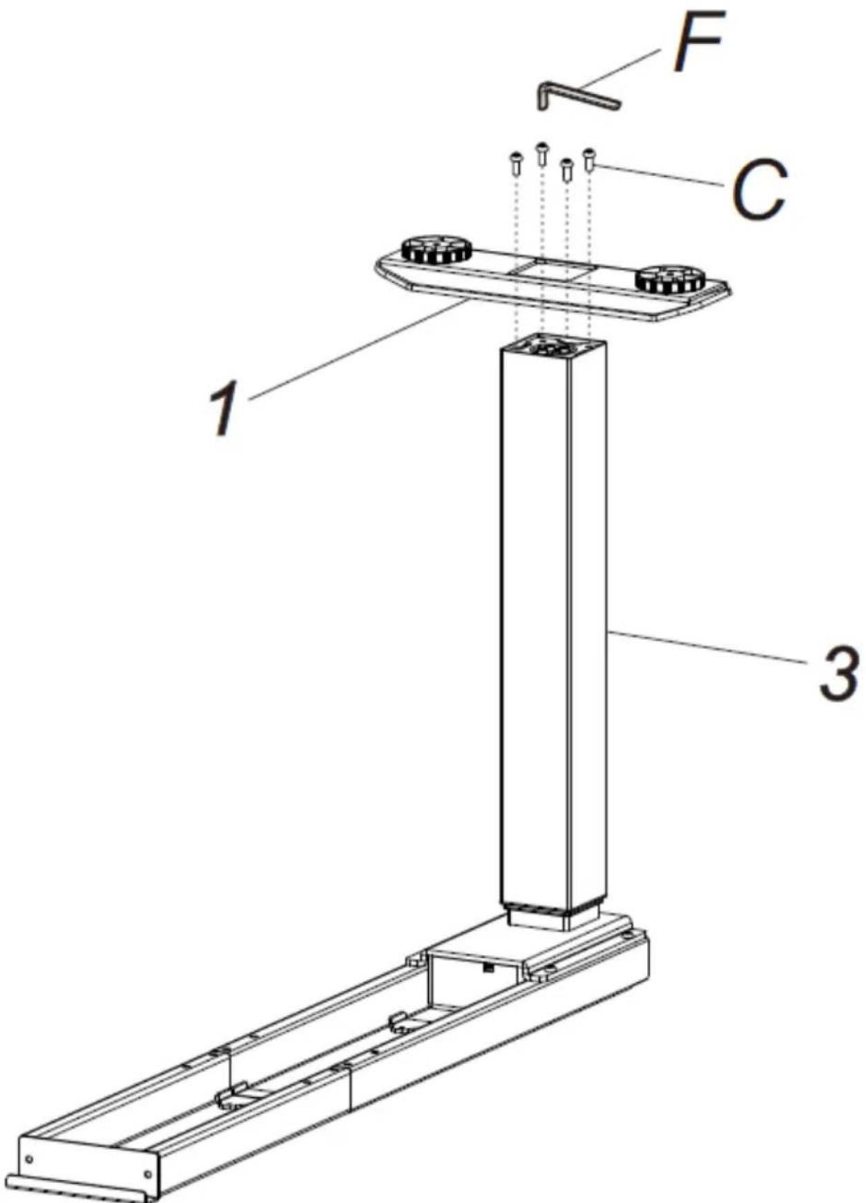
- Screw the long bases (2) to the columns bolted to the support beam (6) and the short base (1) to the column bolted to the side beam (5) using screws (C).
- Screw the brackets (7-9) to the side beam (5) and support beam (6) using the screws (A).
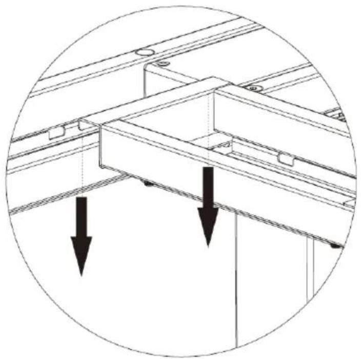
Then hook the side beam to the support beam as shown.
natural_image
Technical diagram of a structural beam with two downward arrows indicating load or force directions (no text or symbols present)EN
- Connect the following to the control box: power cable (12), motor cables (the cable of the furthest motor should be extended with a connecting cable (13), and control panel cable (10).
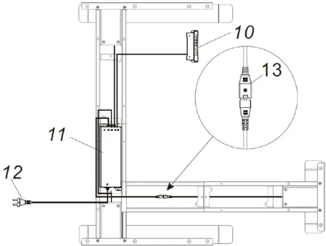
Control box connection diagram (11)
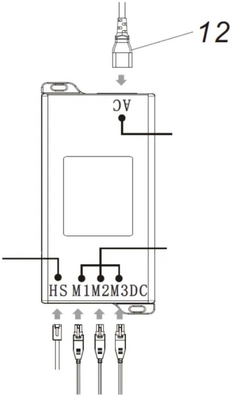
Where:
AC - power socket
HS - control panel socket
M1 - M3 - Connector socket for cables from lifting column motors
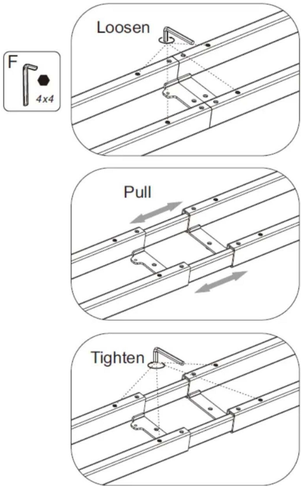
- Adjust the spacing of the side and support beams to the dimensions of the top.
EN
Screw the top to the assembled frame (the top is not delivered with the product).
Screw the control panel and control box to the top.
The figure below shows how to adjust the spacing of the beams:
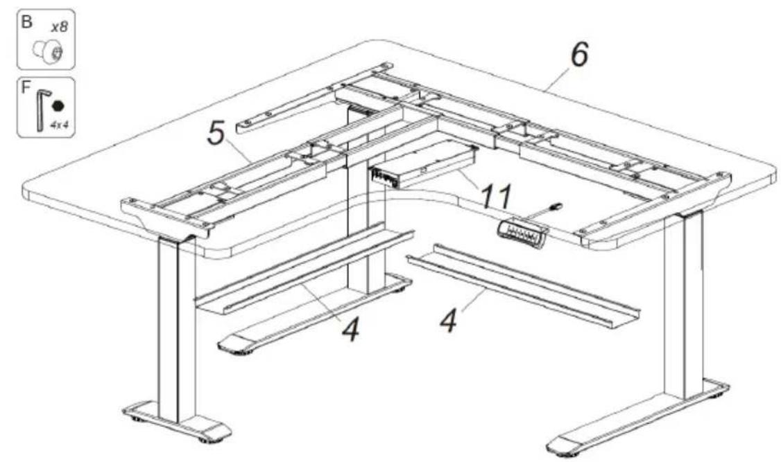
- The final step in assembling the desk is to fix the cable trays (4) according to one of the two methods described below, depending on whether the desk is extended in width or not:
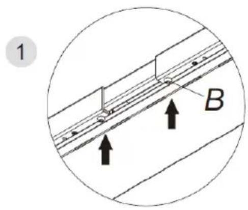
a) Method one
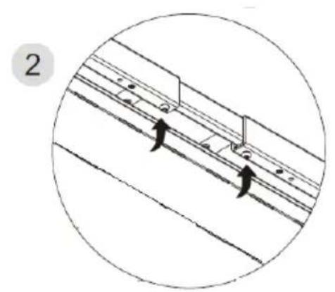
natural_image
Diagram showing two curved arrows pointing to a track or pipeline system inside a circular boundary (no text or symbols)
Gently, without tightening completely, screw the screws (B) into the support beam (6). Then fasten first one side of the trough and then the other side on these screws. Tighten the bolts (B) with an Allen key (F). Secure the trough to the side beam (5) in the same way.
b) Method two
EN

When extending the frame beyond 1720mm, the trough (4) must be mounted in the middle of the support beam. The length of the support beam should not exceed the position of the hole (x) marked in the above drawing. Secure the trough to the side beam as described in method one.
3.3. Working with the unit
-
Connect the unit plug to a power outlet.
-
Adjust the height of the desk frame in one of the following ways:
a) Manually using the buttons (12) and (13). The display (11) will show the current desk height.
b) By recalling one of the three previously saved desk height settings by pressing one of the buttons 1 (14), 2 (15) or 3 (16).
Saving position settings is described later in this manual.
c) Caution: Verifying the correctness of the display after the first start-up of the unit is recommended.
If necessary, perform a reset according to the instructions in point 6.
- Storing the desk height settings in the memory.
Set the preferred desk height using the keys (12) and (13).
Then press the M button (17), "S-" will appear in the display.
Now choose under which number to store the position by pressing one of the buttons 1 (14), 2 (15) or 3 (16), depending on the chosen number the display will show "S-1", "S-2" or "S-3".
- Reminder function for changing position at the desk
- Press button A (18) to activate the function. The display will show "ON" or "on".
- 2s later, while the display screen is flashing, set the alarm time using buttons (12) and (13).
The default setting is 45min (the display shows "==")
To save the settings press any button or wait 5s for the system to automatically save the time.
- During the countdown, any operation on the control panel resets the counter and counts down again.
When the countdown is complete, the display will show: "", and the unit will beep for about 10s.
- When the beep stops, press any button on the display to restart the countdown.
If no action is performed after 10s from the start of the beep, the unit will beep again after 5 minutes.
Further inactivity after the second beep will disable the desk
- To switch off the alarm function press button A (18) for approx. 3s.
The display will show "OFF" or "oFF".
- Collision avoidance settings
A function to avoid collision and damage to the desk. If the desk encounters resistance during height adjustment, the motors will stop and reverse the desk position.
-Press keys (12) and (13) simultaneously for approx. 5s to enter the sensitivity setting.
Each input changes the level by 1 degree, the display indicates the set level.
- Levels description: A0 - function off, A1- low sensitivity, A2- medium sensitivity, A3 - highest sensitivity (factory setting).
- Resetting the unit
To enter the reset mode press and hold the 3 (16) and M (17) buttons, the
display will show "or". rSt
Then press and hold the down button (13) until the desk reaches its lowest position and stops and the display shows the height indication.
Then release the button. The reset is now complete.
If the desk still displays error messages or the height indication is wrong, please contact the manufacturer's service department.
3.4. Cleaning and maintenance
a) Pull out the mains plug before each cleaning and when the unit is not in use.
b) Use only non-corrosive cleaning agents for cleaning the surfaces.
EN
c) After each cleaning, all the parts should be dried well before the unit is used again.
d) Store the unit in a dry and cool place protected from moisture and direct sunlight.
e) Do not spray the unit with a stream of water or immerse it in water.
f) Perform regular inspections of the unit checking technical fitness and any damages.
g) Use a soft, damp cloth for cleaning.
DISPOSAL OF USED UNITS.
At the end of its useful life, this product should not be disposed of with normal household waste but should be taken to a collection point for the recycling of electrical and electronic equipment. This is indicated by the symbol on the product, operating instructions or packaging. The materials used in this unit are recyclable according to their marking. You will be making an important contribution to protecting our environment by reusing, recycling or otherwise disposing of used units.
Your local administration will provide you with information about the appropriate disposal point for used units.
Dane techniczne

natural_image
Technical diagram of a structural frame with two downward arrows indicating load or force (no text or symbols present)natural_image
Diagram of a mechanical assembly with two curved arrows indicating motion or force direction (no text or symbols)

natural_image
Technical diagram of a structural frame with two downward arrows indicating load or force (no text or symbols present)natural_image
Diagram of a mechanical assembly with two curved arrows indicating motion or force direction (no text or symbols)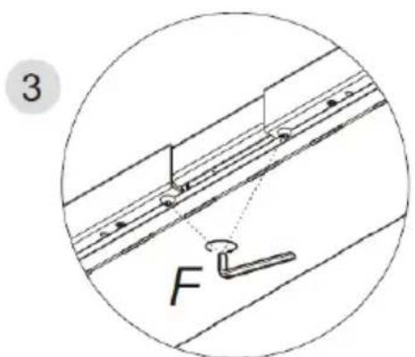

natural_image
Technical line drawing of a structural beam with two downward arrows indicating load or compression (no text or symbols present)natural_image
Diagram showing two parallel lines with directional arrows, no text or symbols present

natural_image
Technical line drawing of a structural beam with two downward arrows indicating load or compression (no text or symbols present)natural_image
Diagram of a mechanical assembly with two curved arrows indicating motion or movement, enclosed in a circle (no text or symbols)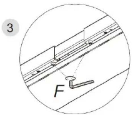

natural_image
Technical diagram of a structural frame with two downward arrows indicating load or force (no text or symbols present)natural_image
Diagram showing two directional arrows pointing to a mechanical or electrical component inside a circular boundary (no text or symbols)

natural_image
Technical diagram of a structural frame with two downward arrows indicating load or force (no text or symbols present)natural_image
Diagram of a mechanical assembly with two curved arrows indicating motion or force direction (no text or symbols)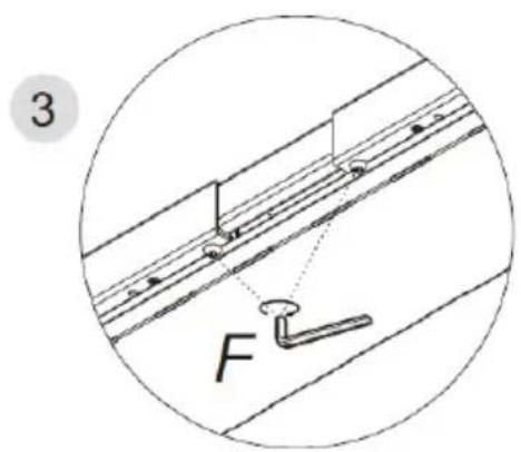
APPARATETS PLACERING
natural_image
Technical diagram of a structural beam with two downward arrows indicating load or force directions (no text or symbols present)natural_image
Diagram of a mechanical assembly with two directional arrows indicating movement or force (no text or symbols present)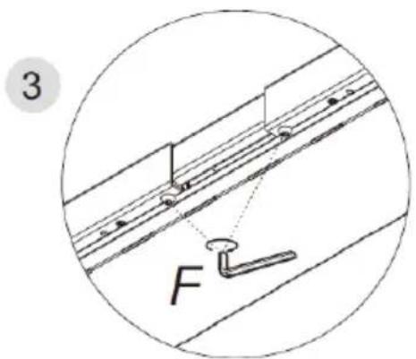
- Kabelgoot
- Elboks
- Rechter beugel
- Linker beugel
- Besturingspaneel
- Hefkolom
- Basis
- Poten
natural_image
Technical diagram of a structural frame with two downward arrows indicating load or force directions (no text or symbols present)NL
natural_image
Diagram showing two curved arrows pointing to a track or pipeline system inside a circular boundary (no text or symbols)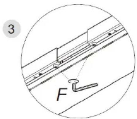
For the disposal of the device please consider and act according to the national and local rules and regulations.
CONTACT
expondo Polska sp. z o.o. sp. k.