
STAR_ATFE_09 - Office Fromm & Starck - Free user manual and instructions
Find the device manual for free STAR_ATFE_09 Fromm & Starck in PDF.

User questions about STAR_ATFE_09 Fromm & Starck
0 question about this device. Answer the ones you know or ask your own.
Ask a new question about this device
Download the instructions for your Office in PDF format for free! Find your manual STAR_ATFE_09 - Fromm & Starck and take your electronic device back in hand. On this page are published all the documents necessary for the use of your device. STAR_ATFE_09 by Fromm & Starck.
USER MANUAL STAR_ATFE_09 Fromm & Starck
Teilelisten
LD - LED-Display
| Parameter description | Parameter value |
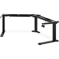
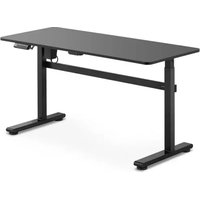
| Product name | CORNER ELECTRIC SIT STAND DESK FRAME |
| Model | STAR_ATFE_09STAR_ATFE_32 |
| Supply voltage [V ~] / Frequency [Hz] | 230-50 |
| Rated power (W) | 450 |
| Protective class | II |
| Dimensions (Width x Depth x Height) [mm] | Left side: 900x680x580Right side: 1100x680x580 |
| Weight [kg] | 43 |
| Number of legs | 3 |
| Maximum load [kg] | 150 |
| Height adjustment range [mm] | 580-1230 |
| Width adjustment range [mm] | Left side: 900-1500Right side: 1100-1900 |
| Maximum travel [mm] | 650 |
| Working cycle*: on/off [min] | 2-18 |
| Maximum adjustment speed [mm / s] | 34 |
CAUTION! After every 2 minutes of continuous operation of the engine, allow the device to cool down and remain idle for at least 18 minutes.
1. General description
The manual is intended to assist in safe and reliable use. The product is designed and manufactured strictly according to technical specifications using the latest technology and components, and maintaining the highest quality standards.
CAREFULLY READ AND UNDERSTAND THIS MANUAL BEFORE STARTING THE WORK.
In order to ensure long and reliable operation of the device, it is necessary to take care of its correct operation and maintenance in accordance with the instructions of this manual. The technical data and specifications in this manual are up to date. The
manufacturer reserves the right to make changes in order to improve quality. Taking into account technical progress and the possibility of reducing noise, the device has been designed and built in such a way that the risk resulting from noise emission is limited to the lowest level.
Symbol explanation
| CE | The product meets the requirements of the relevant safety standards. |
 | Please read the manual before use. |
 | Recyclable product. |
 | CAUTION! or WARNING! or REMEMBER! describing a given situation (general warning sign). |
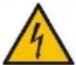 | CAUTION! Warning against electric shock! |
 | Devices of protection class II with double insulation. |
 | For indoor use only. |

CAUTION! The illustrations in this manual are for illustrative purposes and in some details may differ from the actual product.
The original manual is the German version. The other language versions are translations from German.
2. Safety of use

CAUTION! Read all safety warnings and all instructions. Failure to follow the warnings and instructions may result in serious injury or death.
The term "device" or "product" in the warnings and the description of the manual refers to the: CORNER ELECTRIC SIT STAND DESK FRAME.
2.1. Electrical safety
a) The device plug must fit into the socket. Do not modify the plug in any way. Original plugs and matching sockets reduce the risk of electric shock.
b) Do not touch the device with wet or damp hands.
c) Do not use the cord improperly. Never use it to carry the device or to pull the plug out of the socket. Keep the cord away from heat sources, oil, sharp edges or moving parts. Damaged or tangled cords increase the risk of electric shock.
d) If using the device in a humid environment cannot be avoided, a residual current device (RCD) must be used. Using an RCD reduces the risk of electric shock.
e) It is forbidden to use the device if the power cord is damaged or shows visible signs of wear. A damaged power cord should be replaced by a qualified electrician or the manufacturer's service
f) To avoid electric shock, do not immerse the cord, plug or the appliance in water or any other liquid. Do not use the device on wet surfaces.
2.2. Safety at the workplace
a) Keep your working place tidy and well lit. Untidiness or poor lighting can lead to accidents. Be forward-looking, watch what you are doing and use common sense when using this device.
b) In the event of damage or irregularities in the operation of the device, switch it off immediately and report it to an authorized person.
c) If in doubt whether the device is working properly, contact the manufacturer's service.
d) Repairs to the device may only be carried out by the manufacturer's service. It is not allowed to make repairs yourself!
e) In the event of fire, use only dry powder or carbon dioxide (CO2) extinguishers to extinguish the device while it is energized.
f) Keep the operation manual for future reference. Should the device be passed on to third parties, the operation manual should also be handed over with it.
g) Keep packaging elements and small assembly parts out of the reach of children.
h) When using this device together with other devices, also observe the other instructions for use.
2.3. Personal safety
a) The device is not intended to be used by people (including children), who are mentally, sensory or intellectually impaired or without adequate experience and/or knowledge, unless they are supervised by a person responsible for their safety or have been given instructions on how to operate the device.
b) The device may be operated by physically fit, capable and properly trained persons who have read this manual and have been instructed in occupational health and safety.
c) The device is not a toy. Children should be supervised to ensure that they do not play with the device.
2.4. Safe use of the device
a) Do not overload the device. Use tools suitable for the application. Correctly selected device will perform better and safer work for which it was designed.
b) Do not use the device if the ON/OFF switch does not work properly (it does not turn on and off). Devices that cannot be controlled with the switch are dangerous, must not work and must be repaired.
c) Pull the plug out of the socket before making adjustments, changing accessories or storing the device. This preventive measure reduces the risk of accidental starting.
d) When not in use the devices should be stored out of the reach of children and people unfamiliar with the device or this instruction manual. The devices are dangerous in the hands of inexperienced users.
e) Keep the device in good technical condition. Before each work check for general damage or damage related to moving parts (cracks in parts and components or any other conditions that may affect the safe operation of the device). If damaged, have the device repaired before use.
f) The device should be kept out of the reach of children.
g) Repair and maintenance of devices should be performed by qualified persons using only original spare parts. This will ensure safe use.
h) To ensure the designed operational integrity of the device, do not remove factory-installed covers or loosen screws.
i) When transporting and moving the device from the place of storage to the place of use, observe the health and safety regulations of manual transport work applicable in the country where the devices are used.
j) Avoid situations where the device stops under heavy load during operation. This can cause the drive components to overheat and damage the device as a result.
k) Moving parts or accessories must not be touched, unless the device has been disconnected from the power supply.
I) It is forbidden to move, rearrange or rotate the device during operation.
m) The device must be cleaned regularly in order to prevent the permanent accumulation of dirt.
n) The device is not a toy. Cleaning and maintenance must not be made by children without adult supervision.
o) It is forbidden to interfere with the construction of the device in order to change its parameters or construction.
p) Keep the devices away from sources of fire and heat.
q) Do not overload the device.
r) Exceeding the maximum permissible load may damage the product.
s) Inappropriate use of the product, such as sitting on a desk top, may result in damage to the product and/or personal injury.
t) It is forbidden to sit on the desk top to prevent serious personal injury.
u) It is forbidden to move or lie under the desk structure during adjustment. Do not sit or stand on the desk frame. Take special care when adjusting your desk.
v) You should regularly check whether the desk's adjustment mechanism works properly and remove any obstacles which may prevent smooth adjustment.
w) Make sure that the cables, connections and plugs do not interfere with the use of the product.
x) When adjusting the height of the desk, make sure that the lead cables are of sufficient length. Too short cables and connections may make height adjustment difficult or damage other devices.

NOTE! Although the device has been designed to be safe, with adequate means of protection and despite the use of additional user safety elements, there is still a slight risk of accident or injury while working with the device. It is recommended to exercise caution and common sense when using it.
3. Operating rules
The product is intended for supporting and adjusting the height of a desk top. The user is responsible for any damage resulting from misuse.
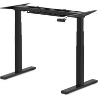
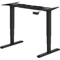
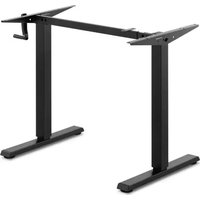
3.1. Device description
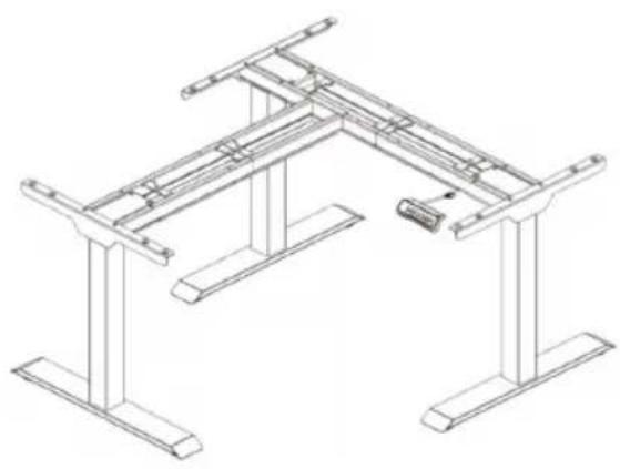
natural_image
Technical line drawing of a structural frame with supports and a small component (no text or symbols)
List of parts
| No. | Image | Name | No. | |
| 1 |  | Footer | 3 | |
| 2 | 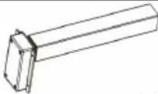 | Lifting column | 3 | |
| 3 | 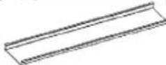 | Cable tray | 2 | |
| 4 | 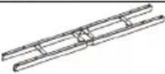 | Cross beam | 1 | |
| 5 | 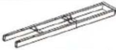 | Auxiliary beam | 1 | |
| 6 |  | Side bracket | 3 | |
| 7 | 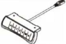 | Control panel | 1 | |
| 8 | 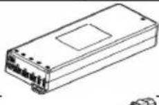 | Control box | 1 | |
| 9 | 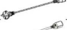 | Power cable | 1 | |
| 10 | 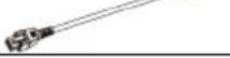 | Signal cable | 1 | |
Accessories list
| No | Image | Type | Quantity |
| A | 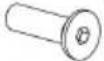 | M6 | 6 |
| B |  | M6 | 8 |
| C | 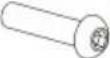 | M6 | 12 |
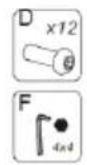
| D |  | M6 | 16 |
| E |  | St4.2 | 24 |
| F | 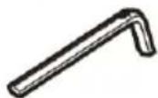 | 4x4mm Allen wrench | 1 |
3.2. Preparation for operation
DEVICE PLACEMENT
The ambient temperature must not exceed 40^ C and the relative humidity must not exceed 85%. The device should be positioned in a way that ensures good air circulation. Keep the device away from any hot surfaces. Always use the device on an even, stable, clean, fireproof and dry surface.
The device should be positioned in such a way that the mains plug can be reached at any time. Make sure that the power supply to the device corresponds to the data given on the rating plate!
DEVICE ASSEMBLY
Before proceeding with the assembly, it is necessary to prepare and secure a suitable space. It is recommended to use a protective mat or pad to prevent scratching the product/floor.
Step 1
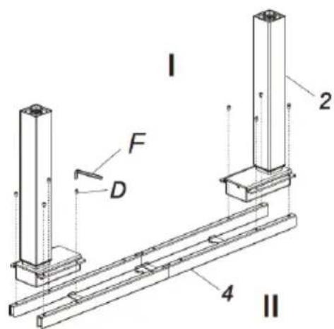
I. Install the cross beam (4).
II. Attach the lifting column (2) to the cross beam (4) using the wrench (F) to tighten the screws (D).
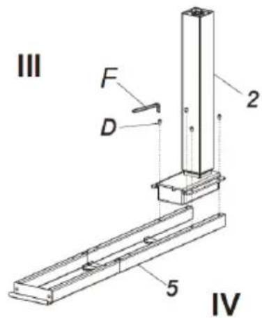
III. Install the auxiliary beam (5)
IV. Attach the lifting column (2) to the auxiliary beam (5) using the wrench (F) to tighten the screws (D).
Step 2
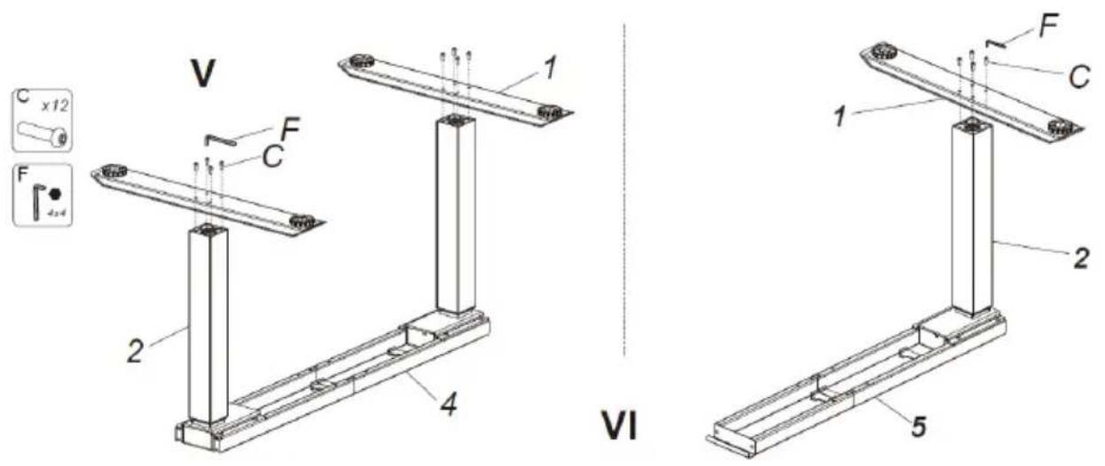
V. Install the footers (1).
VI. Connect the footers (1) to the lifting columns (2) using the wrench (F) to tighten the screws (C).
Step 3
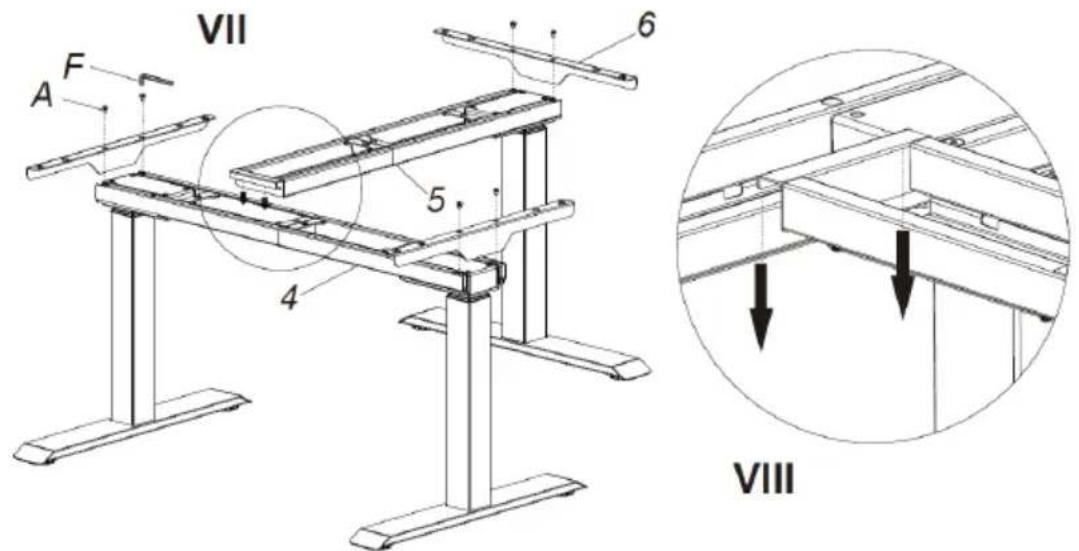
VII. Install the auxiliary beam (5) and the side supports (6).
VIII. Attach the auxiliary beam (5) to the support beam (4), and the specific position can be selected according to the desk top.
Step 4
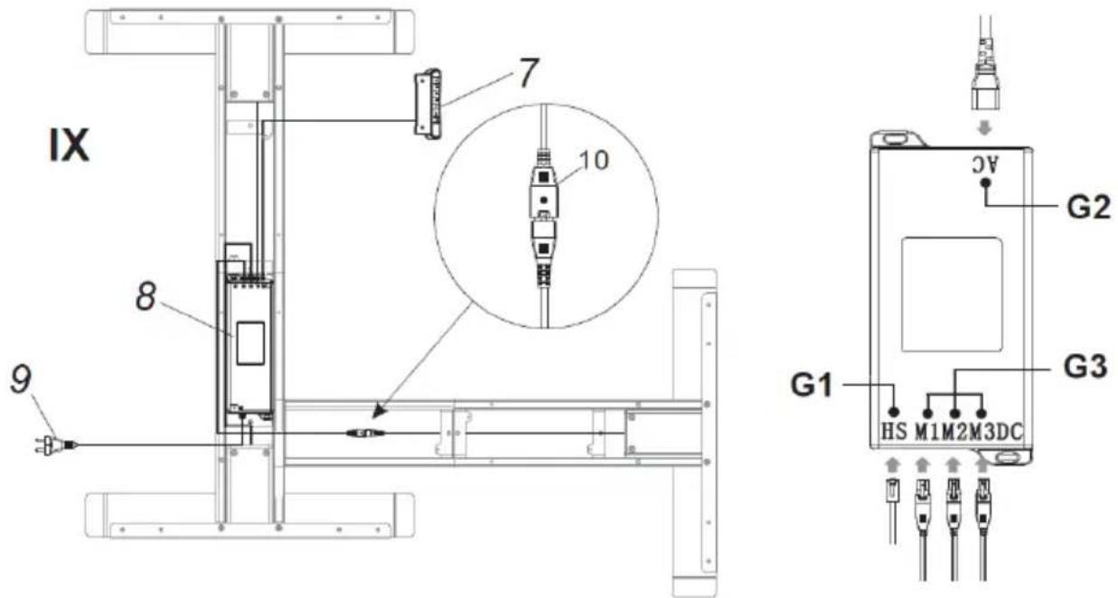
IX. Connect all cables to the sockets in the control box (8):
- connect the signal cable from the control panel to the socket (G1),
• connect the power cord to the socket (G2), - connect the signal cable from the lifting column to the socket (G3).
Step 5
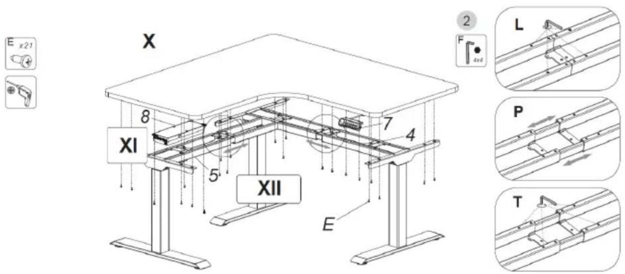
X. Install the desk top, control panel (7) and control box (8).
XI. The control box must be fixed to the desk top.
XII. If an extension of the cross beam is required, proceed as follows:
- loosen (L),
- move (P),
- tighten (T).
Step 6-A
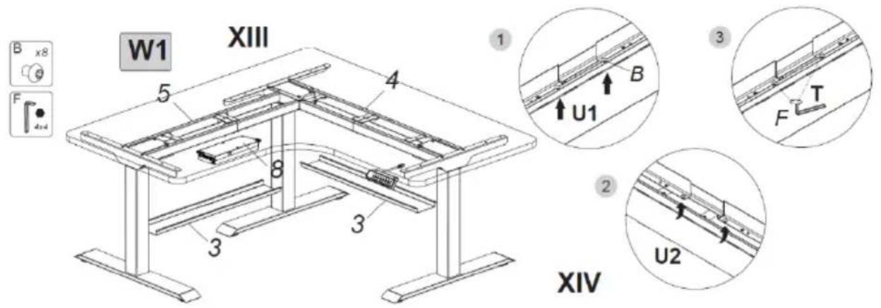
Method 1 (W1)
XIII. Install the cable trays (3).
XIV. Proceed according to the following 3 steps:
- first screw (U1) the bolts (B) into the cross beam (4) using the wrench (F), without tightening it completely,
- slide one side of the cable tray (3) onto the screws (B), and then slide (U2) the other side of the cable tray onto the screws (B),
- finally tighten (T) the screws (B) with the wrench (F).
The cable tray (3) on the auxiliary beam (5) is assembled in the same way.
Step 6-B
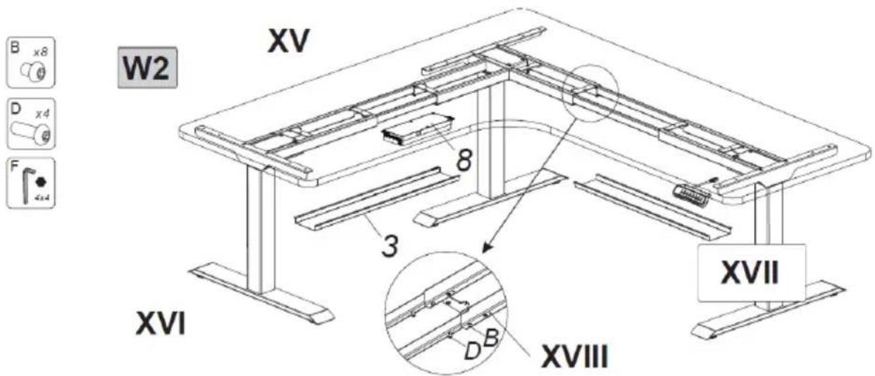
Method 2 (W2)
XV. Install the cable trays (3).
XVI. The installation of the cable tray (3) is the same as in accordance with method 1 (W1) in step 6-A.
XVII. A cable tray (3) should be installed in the middle of the beam joint when the frame is elongated more than 1720 mm.
XVIII. The length of the cross beam should not exceed the limit opening position.
3.3. Working with the device
Height adjustment:
- Connect the plug to the mains supply.
- Use the buttons on the control panel to adjust the height.
CONTROL PANEL DESCRIPTION
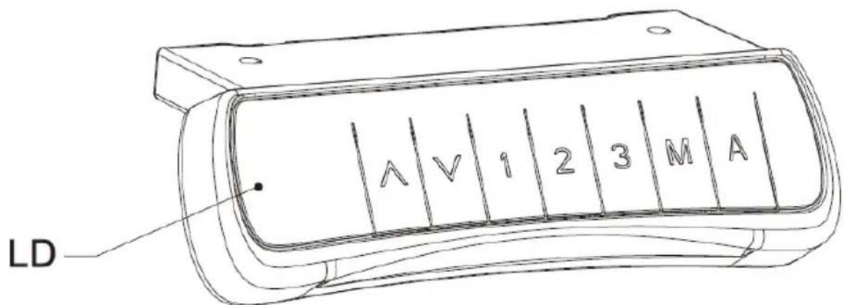
LD - LED display
The control panel has the following 7 buttons:
▲ : height adjustment up button
▼ : height adjustment down button
1 : button for the first user stored altitude position
2 : button for the second user stored altitude position
3 : button for the third user stored altitude position
M : altitude memory function button
A : button to set an alarm to remind the user to change position
Using control panel:
• Height adjustment function:
Use buttons ▲ or ▼ to adjust the height. The current altitude is shown on the LED display.
- Altitude memory function:
a. By pressing buttons ▲ or ▼ you can get the desired height. Press the M button to save the altitude in the memory - S will appear on the display. Then press the button 1, 2 or 3 which will assign the altitude to the pressed button and display accordingly S-1, S-2 or S-3.
b. Pressing the button 1, 2 or 3 will automatically adjust to the stored altitude.
- Reminder function:
a. To activate the reminder function press button A - the display will show ON or on.
b. Two seconds later, press the button ▲ or ▼, to set the reminder time only when the display screen is flashing. The default reminder time is 45 minutes, which is displayed as _45. Then press any button to save the time setting or wait 5 seconds for the system to save the time automatically. During the countdown, each operation will restart the clock. When the countdown is over, the display will show _00 message and the buzzer will sound a 10-second beep.
c. During the 10-second reminder signal, press any button to reactivate the countdown of the time that was set (at point b). If no action is taken during the 10-second reminder signal, another reminder signal will sound after 5 minutes. No action during the second signal will turn off the position change reminder function.
d. To deactivate the position change reminder function, press and hold the A button for three seconds. The LED display will show OFF or oFF.
• Anti-collision sensitivity setting:
a. To set the anti-collision sensitivity, press and hold the ▲ and ▼ buttons simultaneously for 5 seconds. There are 4 levels available (A-3, A-2, A-1, A-0).
b. Marking of anti-collision sensitivity on the display: A-0 - the anti-collision sensitivity function is turned off, A-1 - low sensitivity, A-2 - medium sensitivity, A-3 - high sensitivity. The factory default setting is A-3.
c. When adjusting the height, when the desk top comes into contact with another object, it will stop immediately and retract to avoid damage.
d. Press and hold the ▲ and ▼ buttons simultaneously for 5 seconds. If the above code does not appear on the display, the anti-collision function is inactive.
- Reset:
a. When the LED display shows ASf or rSt, press and hold the ▼ button. The desk top will move to the lowest or highest position and then move in the opposite direction until it stops. The display will show the height number, then release the button ▼. After resetting, you can use your desk as normal.
b. When an error code is displayed, briefly press the ▼ button to go to the state ASf or rSt, and perform the reset operation (as in step a).
c. If your desk still does not function properly after completing the steps above, please contact Customer Service.
3.4. Cleaning and maintenance
a) Before each cleaning, adjustment or replacement of accessories, and also when the device is not used, disconnect the mains plug and let the device cool down completely.
b) Use only non-corrosive products for surface cleaning.
c) After each cleaning, all parts must be thoroughly dried before the device is reused.
d) Store the device in a cool and dry place, protected from moisture and direct sunlight.
e) It is forbidden to spray the device with a stream of water or immerse the device in water.
f) Regularly inspect the device for serviceability and any damage.
g) Use a soft cloth for cleaning.
h) Use a soft, damp cloth for cleaning.
i) Do not use sharp and/or metal objects (e.g. wire brush or metal spatula) for cleaning as these may damage the surface of the device material.
DISPOSAL OF USED DEVICES.
At the end of its service life, this product must not be disposed of with normal household waste but must be taken to a collection point for recycling of electrical and electronic equipment. This is indicated by the symbol placed on the product, operating instructions or packaging. The materials used in this device are recyclable according to their labelling. You make an important contribution to protecting our environment by reusing, recycling or otherwise disposing of used equipment.
Please contact your local authority for the appropriate disposal point.
TROUBLESHOOTING
| The problem | Possible cause | Work |
| No response when pressing ▲ or ▼ buttons after connecting the power. | No cable connection. | Make sure that all cables are securely connected. |
| Low lifting speed or slippage when lowering. | Desk overloaded - maximum load 150 kg. | Ensure that the load on the desk does not exceed 150 kg. |
| The engine does not work as instructed. | Engine problem. | Contact the supplier or retailer. |
| Overloaded. | Duty cycle exceeded: maximum turn-on 2 min / turn-off 18 min. | Restart after disconnecting from power for 18 minutes. |
| Insufficient height whenraising / lowering. | Change of factory settings. | Press and hold the M and 3 buttons at the same time for at least three seconds untilyou hear two continuous beeps indicating that the factory settings have been restored. |
Dane techniczne
natural_image
Technical line drawing of a structural frame with supports and a small device (no text or symbols)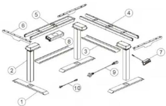
Lista części
natural_image
Technical line drawing of a structural frame with supports and a small component (no text or symbols)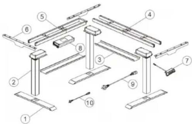
Seznam dílů
LD - LED displej
natural_image
Technical line drawing of a structural frame with supports and a small component (no text or symbols)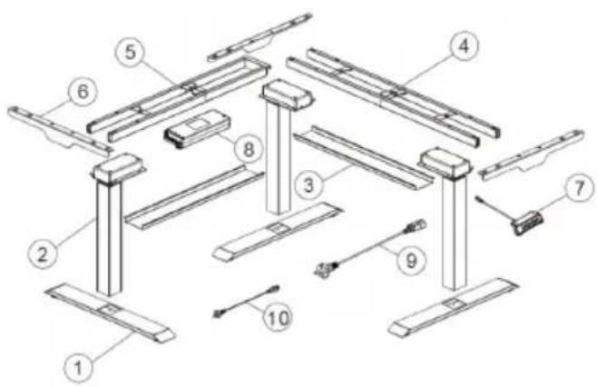
Liste de pièces
LD – Afficheur LED
natural_image
Technical line drawing of a structural frame with supports and a small component (no text or symbols)
LD - Display a LED
Lista de componentes
LD – Pantalla LED
natural_image
Technical line drawing of a structural frame assembly (no text or symbols)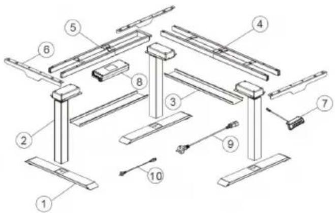
Alkatrészlista
LD – LED kijelző
natural_image
Technical line drawing of a structural support frame with vertical supports and horizontal beams (no text or symbols)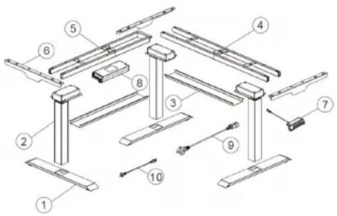
Delnavn
For the disposal of the device please consider and act according to the national and local rules and regulations.
CONTACT
expondo Polska sp. z o.o. sp. k.
- General description
- CAREFULLY READ AND UNDERSTAND THIS MANUAL BEFORE STARTING THE WORK.
- Symbol explanation
- Safety of use
- Electrical safety
- Safety at the workplace
- Personal safety
- Safe use of the device
- Operating rules
- Device description
- Accessories list
- Preparation for operation
- DEVICE PLACEMENT
- DEVICE ASSEMBLY
- Step 1
- Working with the device
- Height adjustment:
- CONTROL PANEL DESCRIPTION
- Using control panel:
- Cleaning and maintenance
- DISPOSAL OF USED DEVICES.
- Dane techniczne
- CONTACT
Brand : Fromm & Starck
Model : STAR_ATFE_09
Category : Office