
STAR_DESK_24 - Office Fromm & Starck - Free user manual and instructions
Find the device manual for free STAR_DESK_24 Fromm & Starck in PDF.

| Product Type | Height-adjustable Crank Desk |
| Brand | Fromm & Starck |
| Model | STAR_DESK_24 |
| Height adjustment range | 730 – 1230 mm |
| Width adjustment range | 820 – 1300 mm |
| Maximum load capacity | 70 kg |
| Lifting speed | 10 mm per crank turn |
| Dimensions (W x D x H) | 820 x 600 x 730 mm |
| Net weight | 16.68 kg |
| Adjustment mechanism | Removable crank with shaft drive |
| Frame material | Steel |
| Cleaning and maintenance | Soft cloth, non-caustic products; regular inspection of fasteners |
| Safety precautions | Do not sit on the desktop; do not exceed 70 kg; use on stable floor; adjustment to be carried out by two people |
| Repairability | Repairs exclusively by the manufacturer's after-sales service; use original parts |
| Package contents | Crossbar, side supports (2), lifting columns (2), drive shaft, lower supports (2), crank, screws, Allen key |
| Warranty | Consult after-sales service for warranty terms |
| Intended use | Height-adjustable desk for indoor use, support for worktop |
Frequently Asked Questions - STAR_DESK_24 Fromm & Starck
User questions about STAR_DESK_24 Fromm & Starck
0 question about this device. Answer the ones you know or ask your own.
Ask a new question about this device
Download the instructions for your Office in PDF format for free! Find your manual STAR_DESK_24 - Fromm & Starck and take your electronic device back in hand. On this page are published all the documents necessary for the use of your device. STAR_DESK_24 by Fromm & Starck.
USER MANUAL STAR_DESK_24 Fromm & Starck
flowchart
graph TD
    A["Initial Component"] --> B["Assembly Step 1"]
    B --> C["Assembly Step 2"]
    C --> D["Final Assembly"]

    subgraph Before Setup
        E["Main Component"] --> F["Assembly Step 3"]
    end

    subgraph After Setup
        G["Final Assembly"] --> H["Assembly Step 4"]
    end
- Wasserwaage
1. General Description
The instruction manual is intended to assist in safe and reliable use. The product is designed and manufactured strictly according to technical specifications using the latest technology and components and maintaining the highest quality standards.
PLEASE CAREFULLY READ AND UNDERSTAND THIS INSTRUCTION MANUAL BEFORE OPERATION,
To ensure long and reliable operation of the unit, make sure to operate and maintain it properly in accordance with the guidelines in this instruction manual. The technical data and specifications contained in this instruction manual are up to date. The manufacturer reserves the right to make changes in order to improve the quality.
Explanation of symbols
 | Please read the instructions before use. |
 | Recyclable product. |
 | CAUTION! or WARNING! or REMINDER! describing a situation.(general warning sign). |
| For indoor use only. |

CAUTION! The illustrations in this instruction manual are for reference only and may differ from the actual product in some details.
The original instruction manual is in the German language version. Other language versions are translations from German.
2. Safety of use

CAUTION! Read all safety warnings and all instructions. Failure to follow warnings and instructions could result in serious injury or even death.
The term "unit" or "product" in the warnings and in the description of the instructions refers to the MANUAL STANDING DESK.
2.1. Safety in the workplace
a) Keep the work area tidy and well lit. Disorder or poor lighting can lead to accidents. Be foresighted, watch what you are doing and use common sense when using the unit.
b) If you have any doubts as to whether the unit is working properly or if it is damaged, contact the manufacturer's service department.
c) Only the manufacturer's service department may repair the unit. Do not carry out repairs yourself!
d) Only the manufacturer's service department can repair the unit. Do not carry out repairs yourself!
e) Keep these instructions for use for future reference. If the unit is to be passed on to a third party, the operating instructions must also be handed over together with the unit.
f) Keep the packaging and small assembly parts out of the reach of children.
g) When using this unit together with other units, also follow the other instructions for use.
2.2. Personal safety
a) Do not operate this unit if you are tired, ill or under the influence of alcohol, drugs or medication that could impair your ability to operate the unit.
b) The unit is not intended to be used by persons (including children) with reduced mental, sensory or intellectual functions or persons who lack experience and/or knowledge unless they are supervised or have been instructed by a person responsible for their safety on how to operate the unit.
c) The unit may be operated by persons who are physically fit, capable of operating it and appropriately trained, and who have read this instruction manual and have been trained in occupational safety and health.
d) Use caution and common sense when operating this appliance. A moment's inattention during operation may result in serious personal injury.
e) The unit is not a toy. Children should be watched to ensure that they do not play with the unit.
2.3. Safe use of the unit
a) Keep the unit in good working condition. Check before each use for general damage or damage to moving parts (cracks in parts and components or any other condition that may affect the safe operation of the unit). If damaged, have the unit repaired before use.
b) Repairs and maintenance should be carried out by qualified personnel using only original spare parts. This will ensure the safety of use.
c) To ensure the designed operational integrity of the unit, do not remove factory-installed covers or loosen screws.
d) When transporting or moving the unit from storage to the place of use, observe the health and safety rules for manual handling applicable in the country where the unit is used.
e) Clean the unit regularly to prevent permanent dirt build-up.
f) The unit is not a toy. Cleaning and maintenance must not be performed by children without adult supervision.
g) Do not tamper with the unit to alter its performance or design.
h) Keep the unit away from sources of fire and heat.
i) Exceeding the maximum allowable load may result in damage to the product.
j) Inappropriate use of the product, such as sitting on the worktop, may result in product damage and/or personal injury. Sitting on the desk top is prohibited to prevent serious injury.
k) Do not move or lie under the desk structure during adjustment. Do not sit or stand on the desk frame. Use extreme caution when making adjustments.
1) Check regularly whether the adjustment mechanism of the desk is working properly and remove any obstacles which may block the smooth adjustment of the desk.

CAUTION! Although the product has been designed to be safe, with adequate safeguards, and despite the additional safety features provided to the user, there is still a slight risk of accident or injury when handling the unit. You are advised to use caution and common sense when using this product.
3. Rules of use
The product is designed to support and adjust the height of the desk top. The user is responsible for any damage resulting from misuse.
3.1. Description
Parts list
| Symbol | Description of the | Drawing | Quantity |
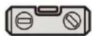
| A | Cross beam | 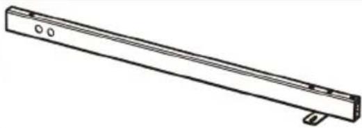 | 1 |
| B | Side bracket |  | 2 |
| C | Lifting column | 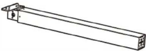 | 1 |
| D | Lifting column | 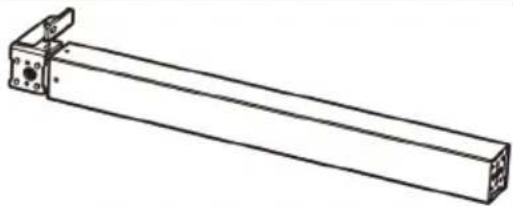 | 1 |
| E | Drive shaft |  | 1 |
| F | Bottom support | 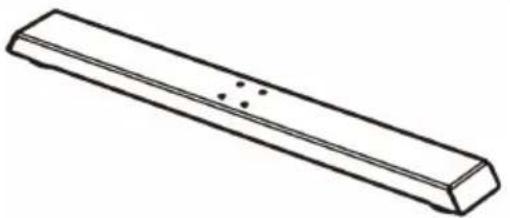 | 2 |
| G | Crank | 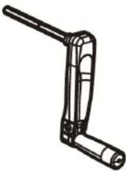 | 1 |
| S-A | Hexagon socket screws |  | 6 |
| S-B | Hexagon socket screws | 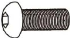 | 8 |
| S-C | Phillips recess head screws and washers | 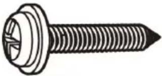 | 10 |
| S-D | Allen key |  | 1 |
3.2. Preparation for operation
POSITIONING OF THE UNIT
Keep the unit away from any hot surfaces. The surface on which the desk will be placed must be even, stable and sufficiently strong.
INSTALLATION
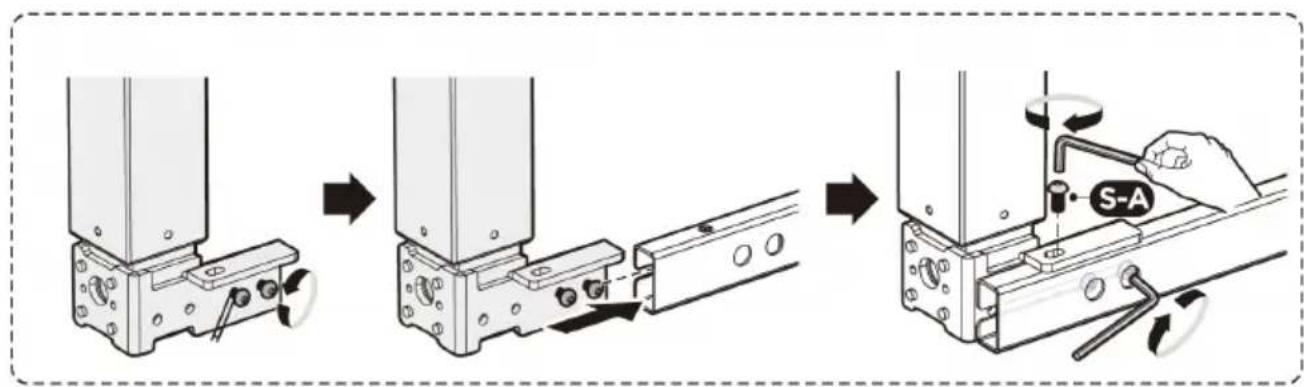
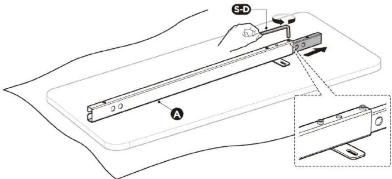
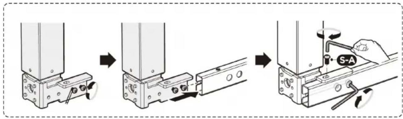
STEP 1: Adjusting the crossbar
- Prepare a large enough surface to allow for convenient and safe installation of the unit.
Placing all the parts of the product on a cardboard pad or other material to protect the floor and mounting components from damage is recommended.
- Carefully place the tabletop (not supplied) with the bottom side facing up.
- Place the crossbar (A) on the table top.
- Loosen the hex socket screws that secure the adjustable crossbar elements (do not remove the screws completely). Slide the adjustable crossbar piece out until the mounting holes are visible.
Caution: The figure shows the rear side of the crossbar. Make sure the crossbar remains facing downward during installation.
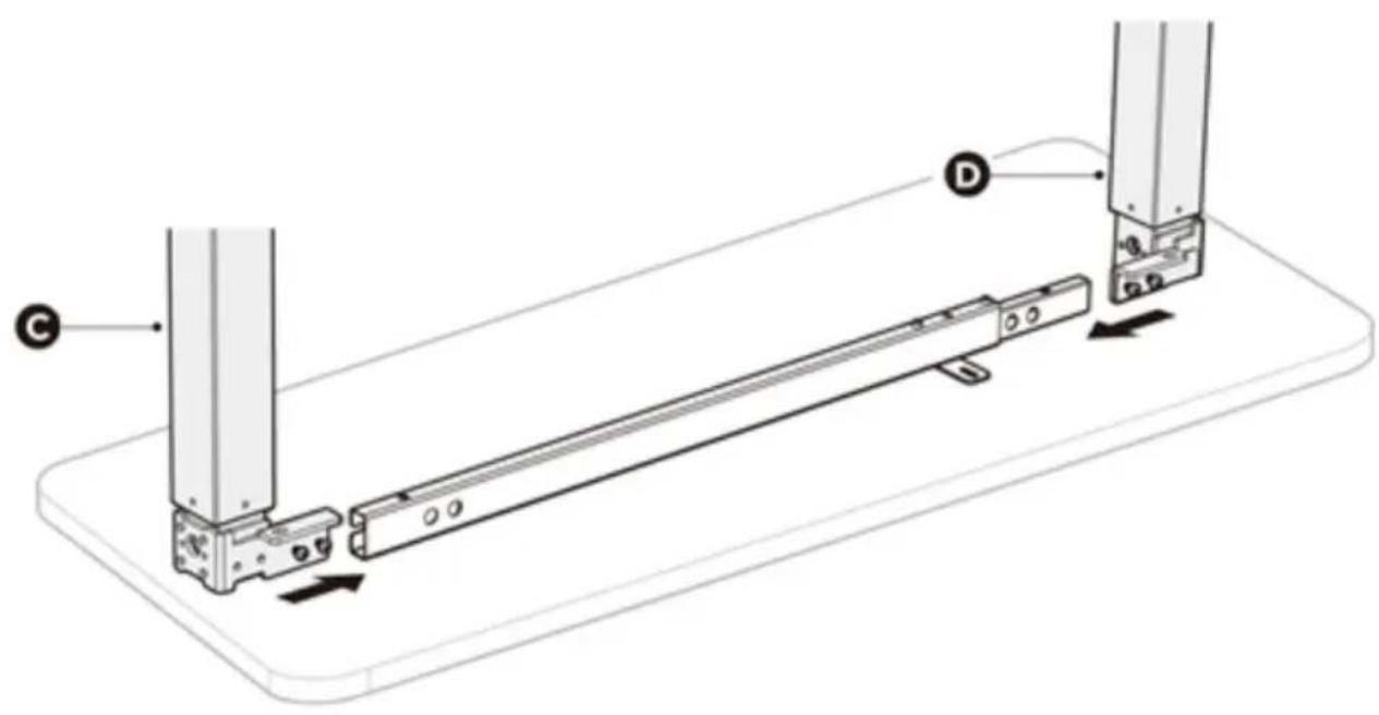
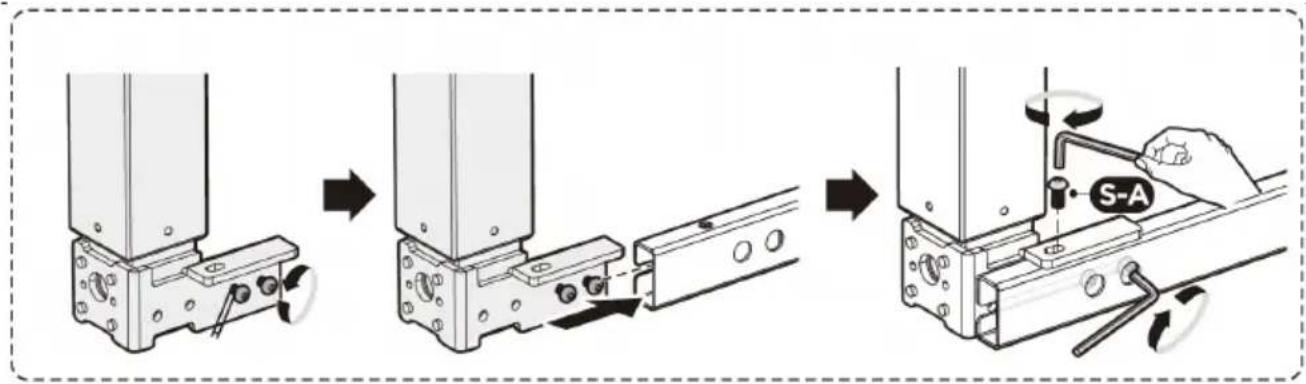
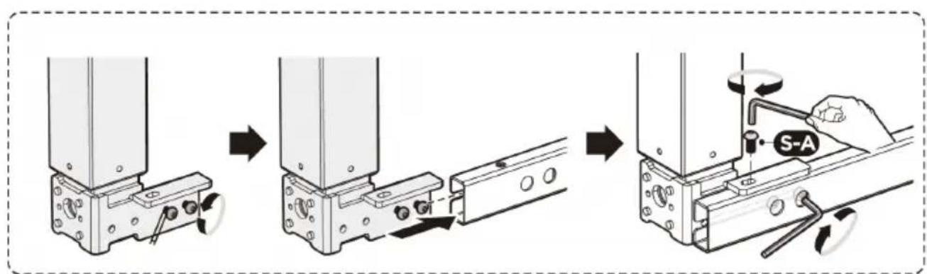
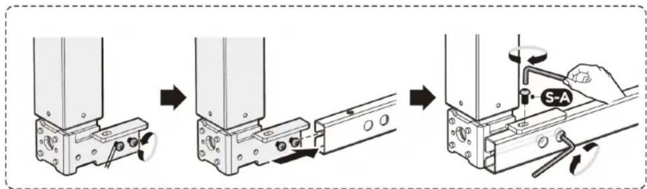
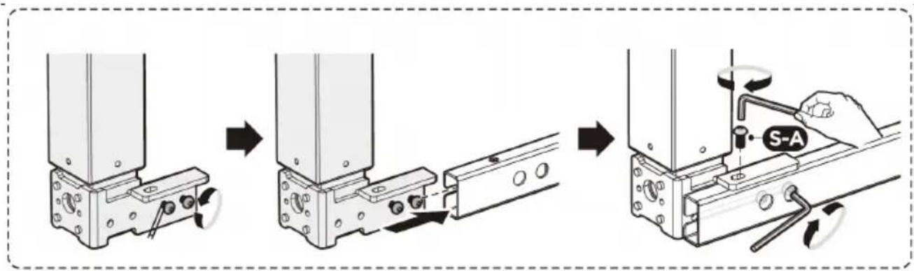
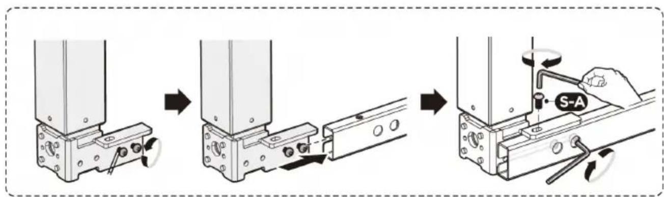
STEP 2: Installing the lifting columns
- Loosen the screws on the lifting columns (C)/(D).
- Slide the lifting column mounting plate onto the crossbar so that the screw heads slide into the slot of the crossbar.
- Align the holes in the mounting plates with the holes in the crossbar (A).
- Attach both lifting columns (C)/(D) to the crossbar with screws (S-A) and Allen key (S-D).
Be sure to tighten the screws inserted into the slot of the crossbeam.
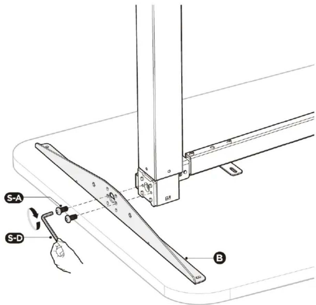
STEP 3: Installing the side brackets
- Attach the side brackets (B) to the sides of the lifting columns using 2 screws (S-A).
Tighten with an Allen key (S-D).
- Repeat the process on the other side of the frame.
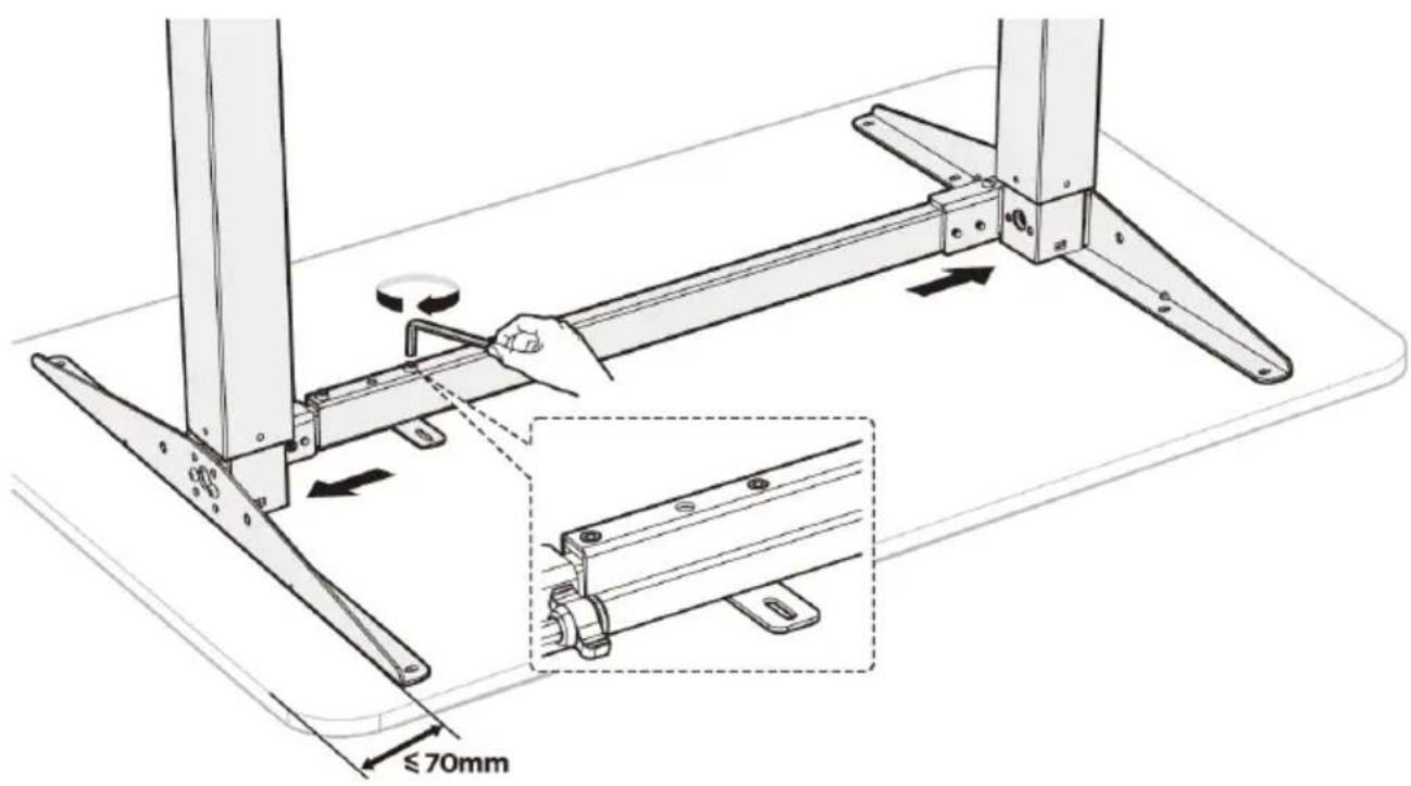
STEP 4: Adjusting the frame
- Adjust the width of the frame to the size of the tabletop. Make sure the frame is positioned in the center. It is recommended that the distance of the side supports (B) to the side edges of the tabletop does not exceed 70mm.
- Tighten all hex socket screws on the crossbar to complete the adjustment.
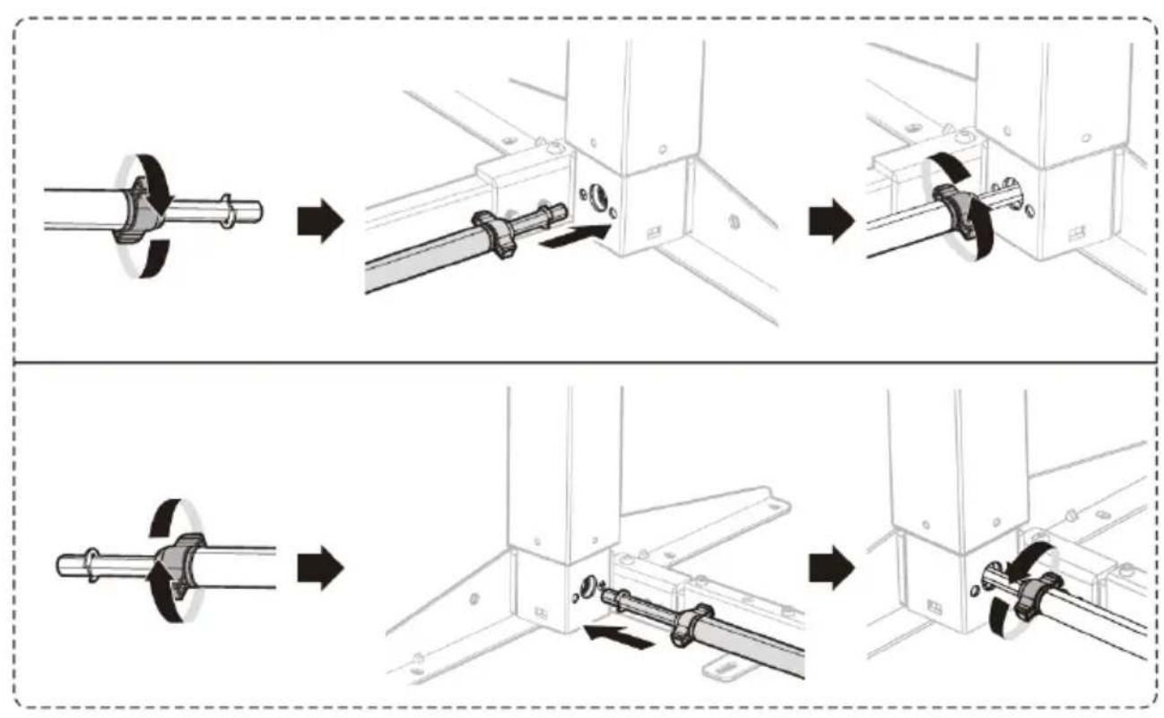
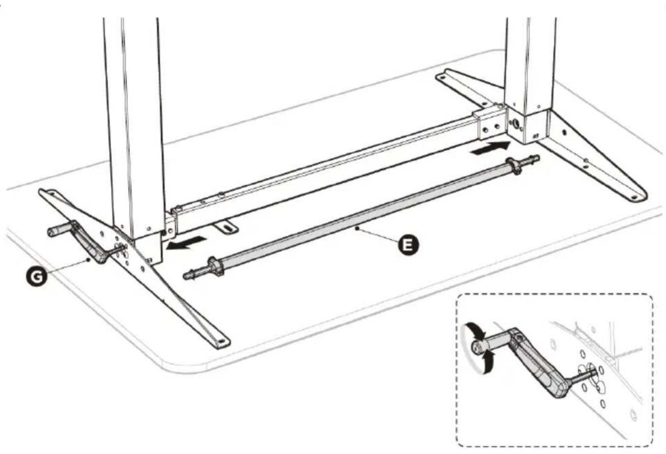
STEP 5: Installing the drive shaft
- Turn the knobs located near both ends of the shaft (E) to allow adjustment of the shaft length.
- Insert both ends of the driveshaft into the holes located in the lifting columns.
- Correctly fit the drive shaft into the hexagonal opening.
Rotate the opening by turning the crank (G) if required.
- After inserting the drive shaft into the openings, tighten the knobs located near both ends of the shaft.

flowchart
graph TD
    A["Initial Component"] --> B["Assembly Step 1"]
    B --> C["Assembly Step 2"]
    C --> D["Final Assembly"]

    subgraph Before Setup
        E["Main Component"] --> F["Assembly Step 3"]
    end

    subgraph After Setup
        G["Final Assembly"] --> H["Assembly Step 4"]
    end
STEP 6: Mounting the top
- Drill holes for the mounting bolts of the crossbar and side brackets.
Caution: The holes should be at least 10 mm deep and at least 3 mm in diameter. - Insert and tighten the 10 screws (S-C) using a Phillips screwdriver.
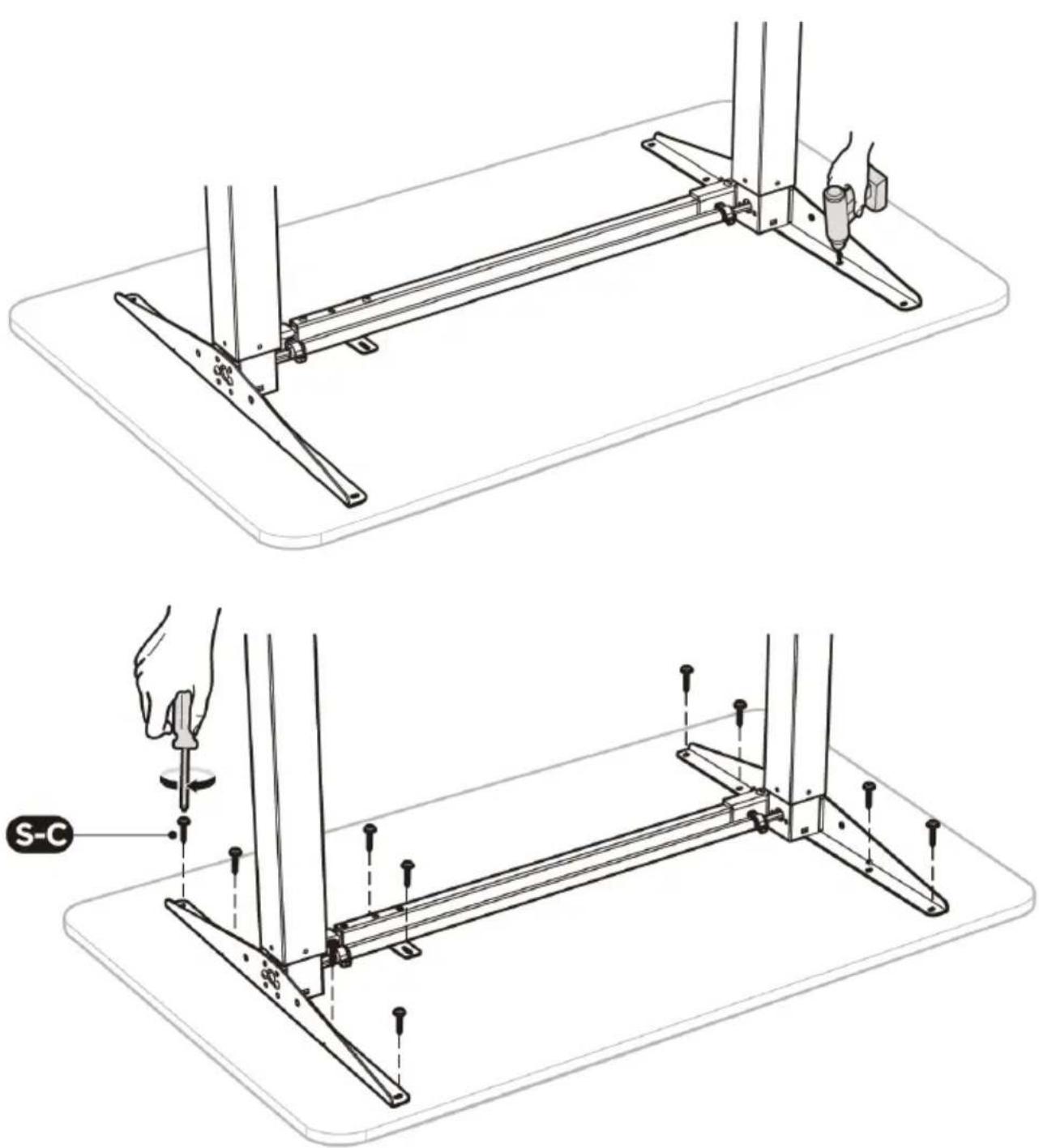
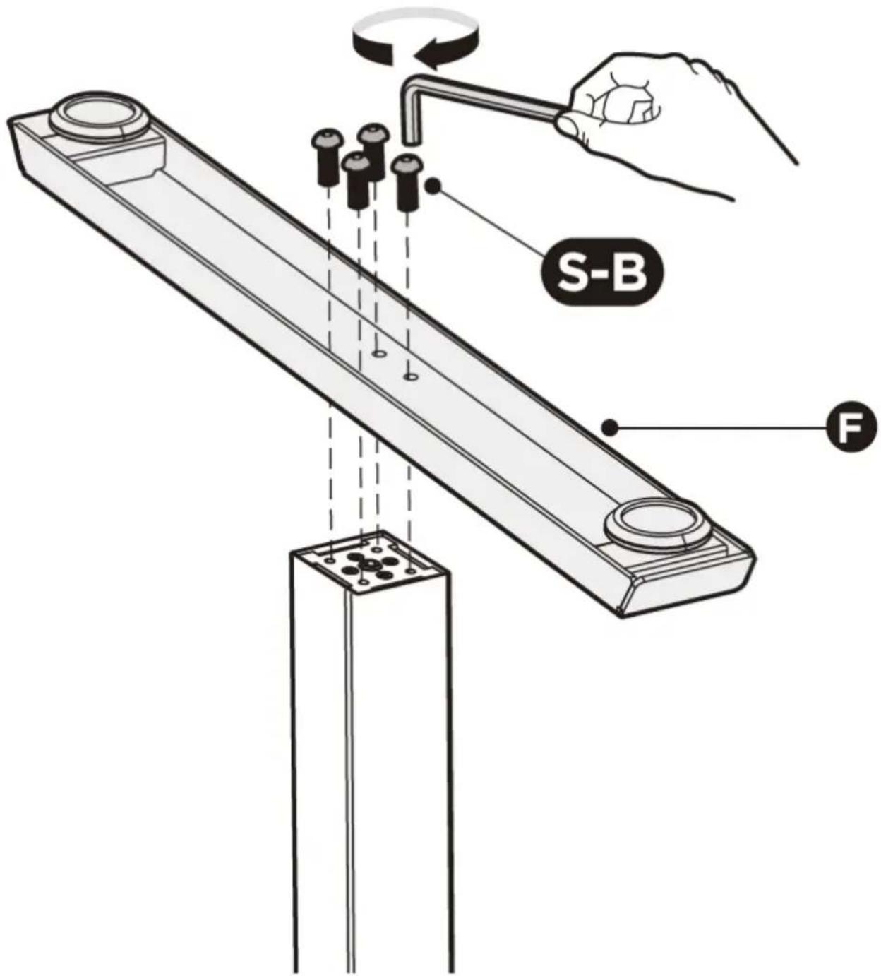
STEP 7: Attaching the bottom supports
- Attach the bottom support (F) to the lifting column (C)/(D) using 4 screws (S-B).
- Repeat the same process to attach the other bottom support.
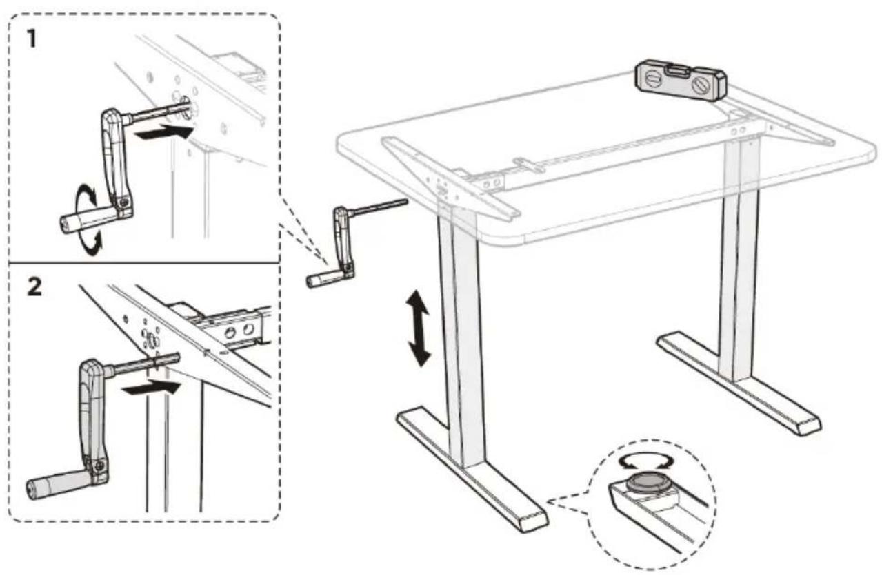
STEP 8: Adjusting the desk
- Turn the desk over with the help of another person, placing it on the bottom supports.
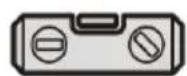
- Leveling: there are two adjustable feet under each bottom support.
If the floor is not level, screw/unscrew the legs (do not unscrew them completely) to adjust the height of each leg and ensure the stability of the desk.
Tip: using a spirit level (not included) to check if the desk is aligned evenly is recommended.
- Height Adjustment:
- Insert the crank into the center hole of the lifting column. By turning the crank, you can adjust the height of the desk.
- Remove the crank from the center hole and insert it into the hole next to it. This will reduce the risk of uncontrolled lowering of the tabletop position.
CAUTION! To avoid injury or property damage, always turn or carry the desk with two people.
- Level
3.3. Cleaning and maintenance
a) Use only non-corrosive cleaning agents for cleaning the surfaces.
b) Store the unit in a dry and cool place protected from moisture and direct sunlight.
c) Perform regular inspections of the unit checking technical fitness and any damages.
d) Use a soft cloth for cleaning.
e) Do not use sharp and/or metal objects (e.g. a wire brush or metal spatula) for cleaning, as these may damage the surface of the material from which the unit is made.
Dane techniczne

flowchart
graph TD
    A["Initial Component"] --> B["Assembly Step 1"]
    B --> C["Assembly Step 2"]
    C --> D["Final Assembly"]

    subgraph Before Setup
        E["Main Component"] --> F["Assembly Step 3"]
    end

    subgraph After Setup
        G["Final Assembly"] --> H["Assembly Step 4"]
    end

- Poziomica

flowchart
graph TD
    A["Initial Component"] --> B["Assembly Step 1"]
    B --> C["Assembly Step 2"]
    C --> D["Final Assembly"]

    subgraph Before
        E["Part 1: Rotated Shaft"]
        F["Part 2: Axial Bracket"]
    end

    subgraph After
        G["Part 3: Axial Bracket"]
        H["Part 4: Axial Bracket"]
    end

- Vodováha

flowchart
graph TD
    A["Initial Component"] --> B["Assembly Step 1"]
    B --> C["Assembly Step 2"]
    C --> D["Final Assembly"]

    subgraph Before Setup
        E["Main Component"] --> F["Assembly Step 3"]
    end

    subgraph After Setup
        G["Final Assembly"] --> H["Assembly Step 4"]
    end

- Niveau

flowchart
graph TD
    A["Initial Component"] --> B["Assembly Step 1"]
    B --> C["Assembly Step 2"]
    C --> D["Final Assembly"]

    subgraph Before Setup
        E["Main Component"] --> F["Assembly Step 3"]
    end

    subgraph After Setup
        G["Final Assembly"] --> H["Assembly Step 4"]
    end

- Livella


flowchart
graph TD
    A["Initial Component"] --> B["Assembly Step 1"]
    B --> C["Assembly Step 2"]
    C --> D["Final Assembly"]

    subgraph Before
        E["Part 1: Rotated Shaft"]
        F["Part 2: Axial Bracket"]
    end

    subgraph After
        G["Part 3: Axial Bracket"]
        H["Part 4: Axial Bracket"]
    end

- Nivel
natural_image
Technical diagram of a mechanical assembly with labeled components (C, D) and directional arrows indicating movement or force (no text or symbols beyond labels)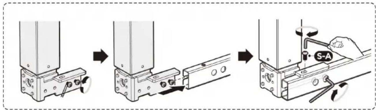

flowchart
graph TD
    A["Initial Component"] --> B["Assembly Step 1"]
    B --> C["Assembly Step 2"]
    C --> D["Final Assembly"]

    subgraph Before Setup
        E["Main Component"] --> F["Assembly Step 3"]
    end

    subgraph After Setup
        G["Final Assembly"] --> H["Assembly Step 4"]
    end
natural_image
Technical line drawings of a mechanical assembly with two views (top and side), showing base, support, and mounting components without any text or symbols.
- Víszintjelző
APPARATETS PLACERING
TRIN 4: Rammeregulering

flowchart
graph TD
    A["Initial Component"] --> B["Assembly Step 1"]
    B --> C["Assembly Step 2"]
    C --> D["Final Assembly"]

    subgraph Before Setup
        E["Main Component"] --> F["Assembly Step 3"]
    end

    subgraph After Setup
        G["Final Assembly"] --> H["Assembly Step 4"]
    end

- Vaterpas
OUR CUSTOMERS' SATISFACTION IS OUR MAIN GOAL! PLEASE CONTACT US WITH QUESTIONS AT:
NASZYM GŁÓWNYM CELEM JEST SATYSFAKCJA KLIENTÓW W PRZYPADKU PYTAŃ PROSIMY O KONTAKT Z PRZEDSTAWICIELEM W DANYM KRAJU:
NAŠÍM HLAVNÍM CÍLEM JE SPOKOJENOST NAŠICH ZÁKAZNÍKŮ! V PŘÍPADĚ OTÁZEK NÁS PROSÍM KONTAKTUJTE NA:
NOTRE BUT PREMIER EST VOTRE SATISFACTION! POUR TOUTE QUESTION, CONTACTEZ NOUS SUR:


- General Description
- PLEASE CAREFULLY READ AND UNDERSTAND THIS INSTRUCTION MANUAL BEFORE OPERATION,
- Explanation of symbols
- Safety of use
- Safety in the workplace
- Personal safety
- Safe use of the unit
- Rules of use
- Description
- Preparation for operation
- POSITIONING OF THE UNIT
- INSTALLATION
- STEP 1: Adjusting the crossbar
- STEP 2: Installing the lifting columns
- STEP 4: Adjusting the frame
- STEP 5: Installing the drive shaft
- STEP 6: Mounting the top
- STEP 7: Attaching the bottom supports
- STEP 8: Adjusting the desk
- Cleaning and maintenance
- Dane techniczne
- APPARATETS PLACERING
- TRIN 4: Rammeregulering
Brand : Fromm & Starck
Model : STAR_DESK_24
Category : Office