COMFORT XS-R1 UP - Sweeper Lavor - Free user manual and instructions
Find the device manual for free COMFORT XS-R1 UP Lavor in PDF.

| Brand | Lavor |
| Model | COMFORT XS-R1 UP |
| Category | Sweeper (Scrubber) |
| Product type | Automatic floor scrubber for flat, rigid, and smooth floors |
| Intended use | Floor washing and vacuuming in civil and industrial environments (hotels, schools, hospitals, factories, shops, offices) |
| Power supply | 24 V batteries (Lead-Acid or Gel) |
| Battery charger | High frequency 24 V / 20 A, built-in |
| Maximum working slope | 2% |
| Maximum transport slope | 10% |
| Vibrations (steering wheel) | 0.26 m/s² |
| Vibrations (seat) | 0.13 m/s² |
| Operating temperature range | +4 °C to +35 °C |
| Storage temperature range | +10 °C to +50 °C |
| Operating humidity | 30% to 95% |
| Driving type | Driver seat, steering wheel, accelerator pedal |
| Brake | Electromechanical with manual release |
| Safety | Emergency stop, thermal circuit breakers, seat occupancy switch |
| Supplied accessories | Brushes, squeegee, squeegee blades, detergent solution filter |
| Routine maintenance | Drain and clean tanks, check blades, clean filter, recharge batteries |
| Warranty | 12 months against defects in materials or workmanship |
Frequently Asked Questions - COMFORT XS-R1 UP Lavor
User questions about COMFORT XS-R1 UP Lavor
0 question about this device. Answer the ones you know or ask your own.
Ask a new question about this device
Download the instructions for your Sweeper in PDF format for free! Find your manual COMFORT XS-R1 UP - Lavor and take your electronic device back in hand. On this page are published all the documents necessary for the use of your device. COMFORT XS-R1 UP by Lavor.
USER MANUAL COMFORT XS-R1 UP Lavor
Technical data plate
A
B


natural_image
Close-up of a mechanical assembly with hoses and a numbered component (1), no visible text or symbols beyond the number.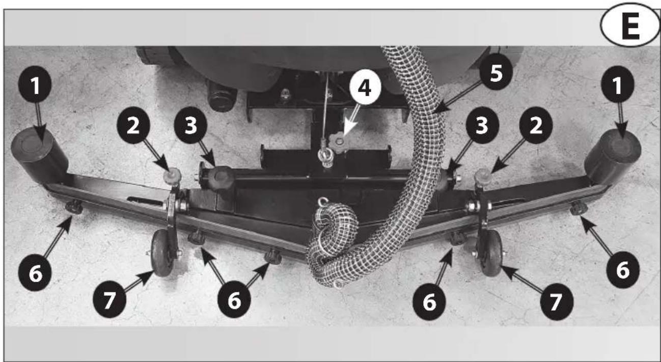
natural_image
Mechanical assembly diagram showing a cylindrical component mounted on a bracket, with no visible text or symbols.


| SW1 SW2 | ||||
| Dip-Switch 1 | Dip-Switch 2 Dip- | Switch 1 Dip-Switch 2 | ||
| Pb-Acid4 x 6V 240Ahc5code 0.107.0034 | ON OFF | OFF OFF | ||
| GelExideSonnenscheinHaze | OFF OFF | OFF OFF | ||
| Gel / AGM OFF | ON OFF OFF | |||
| Pb-Acid4 x 6V 180AhC5code 0.107.0004 | ON ON OFF | OFF | ||
L1
natural_image
Close-up of an aircraft's wheel assembly with a labeled component (1) and an arrow pointing to a mechanical component (no text or symbols beyond label)L2
L3
natural_image
Close-up of a hand adjusting a mechanical component on an aircraft tire (no visible text or symbols)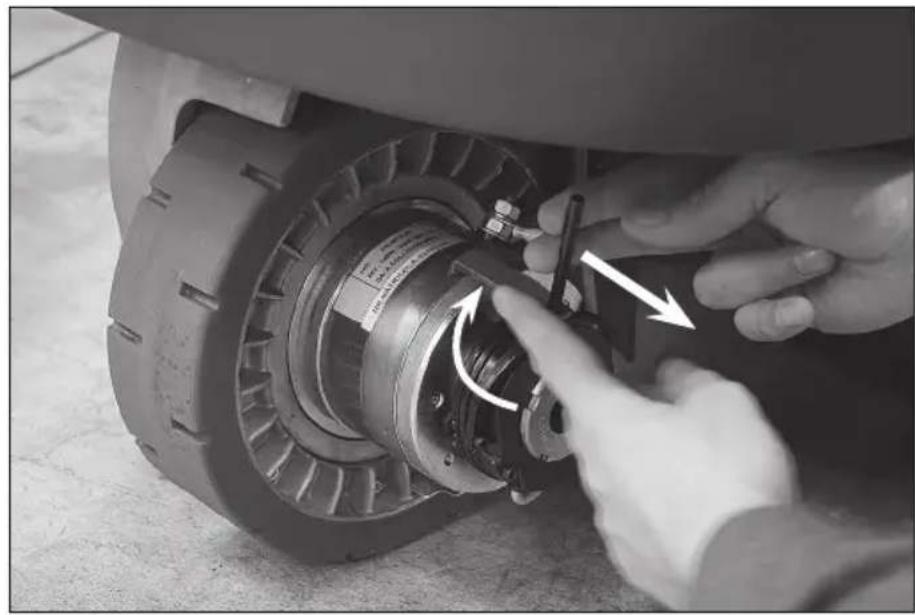
natural_image
Close-up of hands adjusting a mechanical component with arrows indicating motion (no visible text or symbols)L4
natural_image
Close-up of an aircraft's rear wheel assembly with visible mechanical components and mounting brackets (no text or symbols)L5

UP Plus

Essential Vantage

natural_image
Close-up of a car's pedal mechanism with a numbered label (1) indicating a specific component, no readable text or symbols present.
IT
SOMMARIO
FOTO O (Essential / Vantage)
FOTO P (Essential / Vantage)
2.2. NOISE AND VIBRATIONS
- HANDLING INFORMATION
3.1. PACKING LIFTING AND TRANSPORT
3.2. CHECKS UPON DELIVERY
3.3. UNPACKING
3.4. UNBLOCKING THE ELECTROMECHANICAL BRAKE
3.5. LIFTING AND TRANSPORT: MACHINE, BATTERY AND BATTERY CHARGER
- TECHNICAL INFORMATIONS
4.1. GENERAL DESCRIPTION
4.1.1. BATTERY
4.1.2. BATTERY CHARGER
4.2. STRUCTURE AND FUNCTIONS
4.2.1. MACHINE
4.2.2. BATTERY
4.3. BATTERY CHARGER CONFIGURATION
4.4. ACCESSORIES
- INSTALLATION INFORMATION
5.1. BATTERY PREPARATION
5.2. BATTERY INSTALLATION AND PREPARATION
5.3. SETTINGS THROUGH THE CONTROL PANEL
5.4. MACHINE PREPARATION
6.2. SQUEEGEE AND SPLASH GUARD ASSEMBLY, DISASSEMBLY AND ADJUSTMENT
6.2.1. SQUEEGEE ASSEMBLY
6.2.2. SQUEEGEE DISASSEMBLY
6.2.3. SQUEEGEE BLADES DISASSEMBLY/ASSEMBLY
6.2.4. SQUEEGEE ADJUSTMENT
6.2.5. SPLASH GUARD ASSEMBLY/DISASSEMBLY
6.3. ACCESSORY ASSEMBLY/DISASSEMBLY (BRUSHES, PAD DRIVERS AND ABRASIVE DISKS)
6.4. FILLING AND DRAINING THE DETERGENT SOLUTION TANK
6.5. DRAINING THE RECOVERY TANK
6.6. DRIVING THE MACHINE
6.7. WORK METHOD
6.7.1. PREPARATION AND WARNINGS
6.7.2. DIRECT SCRUBBING OR FOR SLIGHTLY DIRTY SURFACES
6.7.3. INDIRECT SCRUBBING OR FOR VERY DIRTY SURFACES
6.7.4. POST-SCRUBBING OPERATIONS
6.8. INFORMATIONS ABOUT THE USE OF MODEL (UP / PLUS)
- MAINTENANCE INFORMATION
7.1. TAN KS
7.2. SUCTION HOSE
7.3. SQUEEGEE
7.4. ACCESSORIES
7.5. CLEANING SOLUTION FILTER
7.6. MACHINE BODY
7.7. BATTE R IES
7.8. FUSES AND THERMAL BREAKERS
7.9. PERIODIC MAINTENANCE
8.2. PROBLEM SOLVING GUIDE
8.2.1. THE MACHINE DOESN'T WORK
8.2.2. THE MACHINE DOESN'T MOVE FORWARD
8.2.3. THE BRUSHES DON'T ROTATE
8.2.4. NOT ENOUGH OR TOO MUCH DETERGENT
8.2.5. NO SUCTION
8.2.6. INSUFFICIENT SUCTION
8.2.7. THE BRUSH MOTOR OR THE SUCTION MOTOR DOESN'T STOP
8.2.8. THE SQUEEGEE DOESN'T CLEAN OR DRY EFFICIENTLY
8.2.9. THE BATTERY CHARGER DOESN'T WORK
8.2.10. THE BATTERIES DO NOT CHARGE OR DO NOT HOLD A CHARGE
- CONDITIONS OF WARRANTY
9.1. SCRAPPING OF THE MACHINE
9.2. DISPOSAL (WEEE)
1. GENERAL INFORMATION
1.1. MANUAL PURPOSE
To make it easier to read about and look up various subjects, refer to the table of contents at the beginning of the section in your language.
This manual has been prepared by the manufacturer and is an integral part of the product. As such, it must be kept in a safe place for the machine's entire service life until demolition.
The customer must ensure that machine operators have read or are familiar with the contents of this manual so that they strictly follow the instructions described herein.
Constant compliance with the instructions provided in this manual is the only way to guarantee the best results in terms of safety, performance, efficiency and service life of the product you now own. Non-compliance with these rules may cause injuries to people and damage to the machine, the scrubbed surface and the environment: in no case can such injuries or damage be attributed to the manufacturer.
This manual refers in detail to the machine and provides instructions and descriptions only about our batteries and battery chargers (optional).
The batteries and the battery charger are basic complementary machine parts and will affect its operation in terms of running time and performances. Only the correct combination of the two accessories (batteries and battery charger) will ensure the highest possible performances and avoid wasting lots of money. For more detailed information refer to the special battery and battery charger manuals.
Our recommended battery chargers and batteries (optionals) ensure the best combination with the machine and offer outstanding versatility (battery charger) as well as the category's highest quality and performance standards.
1.2. TERMINOLOGY AND SYMBOL LEGEND
For the sake of clarity and to efficiently highlight the various aspects of the instructions provided, terms and symbols were used that are defined and illustrated here below:
- Machine. This definition replaces the commercial name to which this manual refers.
- Operator. 'operator' means the person or persons given the task of installing, operating, adjusting, maintaining, cleaning, repairing or transporting machinery.
- Technician. A technician is considered a person who has the experience, technical education, legislative and regulatory knowledge that allows him to carry out any type of required work, and the ability to recognise and to avoid possible risks during machine installation, and maintenance.
- INDICATION SYMBOL. Particularly important information to avoid machine malfunctions.
⚠ - ATTENTION SYMBOL . Very important information to avoid serious damage to the machine and to the environment in which it operates.
- DANGER SYMBOL Vital information to avoid serious (or extreme) consequences affecting the health of persons and causing damage to the product and the environment in which it operates.
Total weight (ready to operate)
Max. working range incline 2% (Max. transporting range incline 10%)
Rated power brush drive
Rated power suction turbine
1.3. PRODUCT IDENTIFICATION
The nameplate located under the dashboard, above the battery connector, contains the information.
1.4. SPECIFIC USE
This appliance is suited for the commercial use, e.g. in hotels, schools, hospitals, factories, shops, offices, and rental companies.
This machine is a floor scrubber-drier: it must be used to scrub and to vacuum liquids of flat, rigid, horizontal, smooth or moderately rough and uniform floors that are free from obstacles in both civic and industrial environments. Any other use is prohibited.
Please refer very carefully to the safety information reported in this manual.
The scrubber-drier distributes a quantity of a water and detergent solution (adjustable) on the surface to be cleaned, while the brushes remove any dirt on the ground. The machine's suction system, using a ground squeegee, perfectly dries the liquids and the dirt just removed from the front brushes in a single pass.
By efficiently combining a cleaning detergent with various types of brushes (or abrasive disks), the machine can adapt to all the various combinations of floors and dirt.
1.5. TECHNICAL MODIFICATIONS
The manufacturer reserves the right to make technical modifications to the product, without prior notice, in order to make the necessary technical upgrades or improvements. For this reason, some details of your machine may be different from the information in the sales catalogues or from the illustrations presented in this booklet. However, this will not reduce safety or invalidate the information supplied to this regard.
2. SAFETY INFORMATIONS
2.1. BASIC RECOMMENDATIONS
Carefully read the "instruction manual" before starting, using, performing unscheduled or routine maintenance or any other work on the machine.
⚠ Rigorously comply with all the instructions provided in this manual and in those for the batteries and battery chargers (with particular attention to warnings and danger notices).
The manufacturer will not be held responsible for injuries to persons or damage to property due to non-compliance with the aforementioned instructions.
This machine must be powered only with the safety extra-low voltage indicated on the technical data plate.
Before using the machine, make sure that each part is in the correct position.
The appliance is not intended for use by persons (including children) with reduced physical, sensory or mental capabilities, or lack of experience and knowledge, unless they have been given supervision or instruction concerning use of the appliance by a person responsible for their safety.
Children should be supervised to ensure that they do not play with the appliance.
⚠ Do not operate this machine for any other purpose except for the use for which it was specifically designed. Evaluate the type of building where it will be utilised and rigorously comply with the current safety regulations and conditions.
Do not use the machine in places without adequate lighting, in explosive environments, when harmful dirt is present (dust, gas, etc.), on roads or public passage ways and in outdoor environments in general.
The machine operating temperature range is +4°C to +35°C; when not being used, store the machine in a dry and non-corrosive environment within a temperature range of between +10°C and +50°C.
When using the machine under any condition the humidity must range between 30% and 95%.
Never use or vacuum liquids, gases, dry dust, acids and solvents (e.g. paint thinners, acetone, etc.), even if diluted, inflammables or explosives (e.g. petrol, fuel oil, etc.); never vacuum flaming or incandescent objects.
Do not use the machine on slopes or ramps steeper than 2%.; for small slopes, do not use the machine sideways, always handle it with caution and never move backwards. When transporting the machine on steeper ramps or slopes 10%, be very careful to avoid tipping and/or uncontrolled accelerations. Use only the lowest speed! The machine can be handled on ramps and/or steps only with the brush head and squeegee lifted off the ground.
⚠️ If the floor scrubber-dryer is used on a downward slope, moderate the speed and do NOT disconnect the ANDERSONN battery connection plug. Failure to observe this indication provided may lead to serious damage to the electronic control system and void the warranty terms.
⚠️ Never park the machine on a slope.
The machine should never be left unattended with the motors running; it can be left unattended only after turning off the motors, ensuring that it won't make any accidental movements and disconnecting it from the electric power supply.
Make sure there are no other persons, and children in particular, in the area where the machine is being used.
⚠ Do not use the machine to transport persons/things or to tow objects. Do not tow the machine.
Do not use the machine as a support surface for any weight for any reason.
Do not block the ventilation and heat dispersion openings.
⚠️ Do not remove, modify or by-pass the safety devices.
Always use individual safety devices to ensure operator safety: aprons or safety overalls, non-slip and waterproof shoes, rubber gloves, goggles and earphones, and masks to protect the respiratory tract. Before starting to work, remove necklaces, watches, ties and other objects that may cause serious injuries.
⚠ Do not insert hands between moving parts.
Do not use detergents that differ from those required and follow the instructions indicated on the relative safety sheets. Detergents should be stored in a place that is inaccessible to children. In case of contact with the eyes, rinse immediately with copious amounts of water and, if swallowed, immediately consult a physician.
Make sure that the battery charger power sockets are connected to an efficient earthing system and that they are protected by magnetothermal and differential circuit-breakers.
If you are going to equip the machine with dry (gel) batteries, be sure the battery power indicator on the control panel, has been set properly. Check this procedure with your dealer.
⚠ Follow the battery manufacturer's instructions and comply with legal provisions. The batteries should always be clean and dry to avoid surface leakage currents. Protect the batteries against impurities, such as metallic dust.
Do not place tools on top of the batteries: they may cause a short-circuit or an explosion.
When using battery acid, rigorously respect the relative safety instructions. In the presence of particularly strong magnetic fields, evaluate the possible effect on electronic control devices.
Never spray water on the machine to clean it.
Recovered fluids contain detergents, disinfectants, water, as well as organic and inorganic material collected during work operations: dispose of them in accordance with current legal provisions.
⚠️ If the machine malfunctions and/or operates inefficiently, turn it off immediately (disconnecting it from the electric power supply or from the batteries) and do not tamper with it.
Contact one of the manufacturer's technical service centres.
All maintenance or accessory replacement operations must be carried out in environments with adequate lighting and only after having disconnected the machine from the electric power supply by detaching the battery connector.
All work on the electrical system and all maintenance and repair operations (especially those not explicitly described in this manual) should be carried out only by authorised service centres or by specialised technical personnel who are experts in the sector and in the pertinent safety regulations.
The machine owner can only use original accessories and spare parts supplied exclusively by the manufacturer since such parts are the only ones that guarantee that the equipment will operate safely without any problems. Do not use parts disassembled from other machines or other kits as spare parts. In addition, it is recommended to eliminate those parts of the machine that may be dangerous, especially for children.
Before each use, check the machine and, in particular, check that the battery charging cable and the connector are in good condition and safe for use. If they are not in perfect condition, do not use the machine for any reason until an authorised specialist repairs the defective parts.
If foam or liquid is noted, immediately turn off the suction motor.
Do not use the machine on textile flooring, such as rugs, carpeting, etc.
Wax, foaming detergents or dispersions along the hoses may cause serious problems for the machine or clog the hoses.
2.2. NOISE AND VIBRATIONS
For informations relating to noise and vibration data see last page.
3. HANDLING INFORMATION
3.1. PACKING LIFTING AND TRANSPORT
During all lifting or transport operations, make sure that the packed machine is securely anchored to prevent it from tipping over or falling accidentally. Transport vehicle loading and unloading operations must be carried out with adequate lighting.
The packed machine must be handled using adequate devices, making sure not to damage/strike any part of the packing, not to tip it over and to be very careful when placing it on the ground.
All these instructions also apply to the batteries and the battery charger.
3.2. CHECKS UPON DELIVERY
When the goods are delivered (machine, battery or battery charger) by the transporter, carefully check the condition of the packing and its contents. If the contents have been damaged, notify the transporter and reserve the right, in writing (select the word "reserve" on the document), to submit a claim for compensation before accepting the goods.
3.3. UNPACKING
⚠ Wear safety clothing and use adequate tools to limit the risks of accidents.
Carry out the following steps if the machine is packed with a cardboard housing:
- Use scissors or clippers to cut and eliminate the plastic straps.
- Slip off the cardboard housing from the top of the packed machine.
- Remove the envelops inside and check their contents (use and maintenance manual, battery charger connector)
- Remove the metallic brackets or plastic straps that secure the machine to the pallet.
- Release the brushes and the squeegee from the packing.
- Take the machine off the pallet (pushing it backward) by using an inclined surface that is solidly attached to the floor and to the pallet.
If the machine is packed in a wooden crate:
- Detach all the wooden sides from the pallet, starting from the top one.
- Remove the protective film wrapped around the machine.
- Remove the metallic brackets or plastic straps that secure the machine to the pallet.
- Release the brushes and the squeegee from the packing.
- Take the machine off the pallet (pushing it backward) by using an inclined surface that is solidly attached to the floor and to the pallet.
Take the same precautions and follow the same instructions to remove the optional battery charger from the packing (holding the special handles to extract it from the top of the packing) and the optional battery.
After moving the machine away from all the packing, start mounting the accessories and the batteries as per the instructions provided in the specific section.
Keep all the pieces of the packing since they might be useful in the future to protect the machine and the accessories during transport to another location or to
authorised service centres. If not, the packing can be disposed in accordance with current disposal laws.
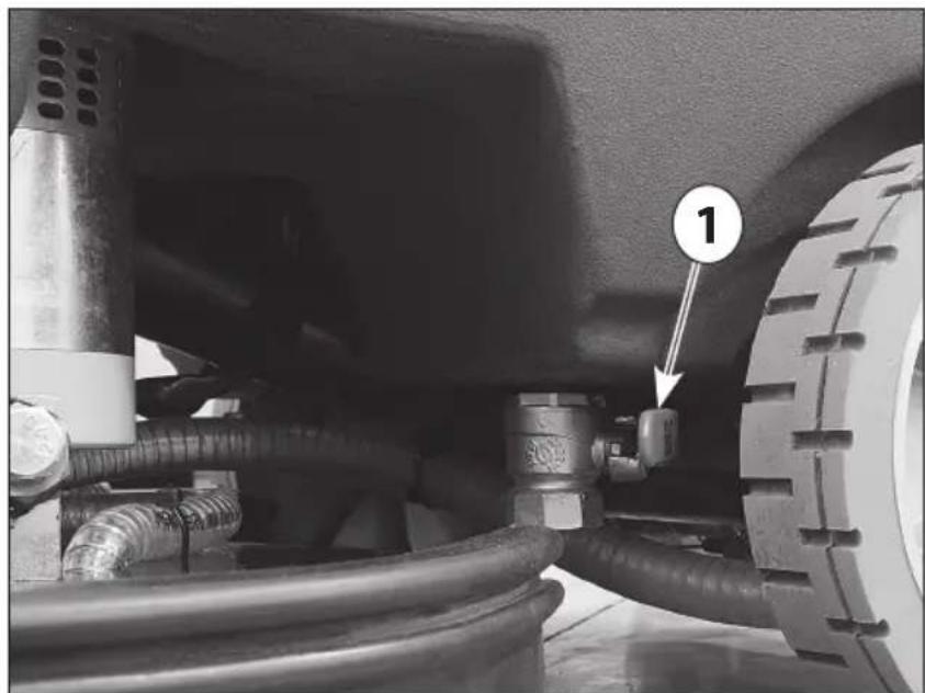
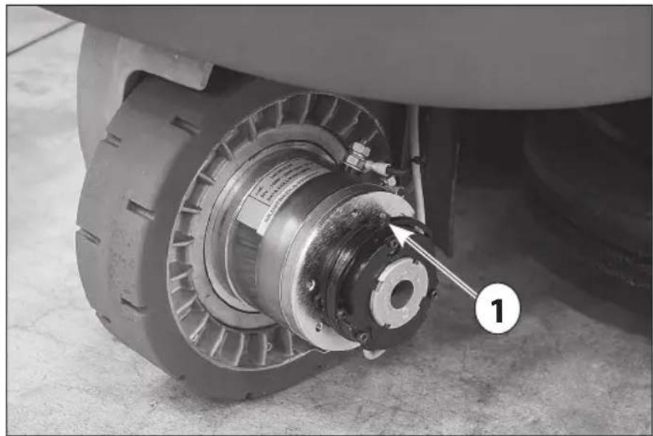
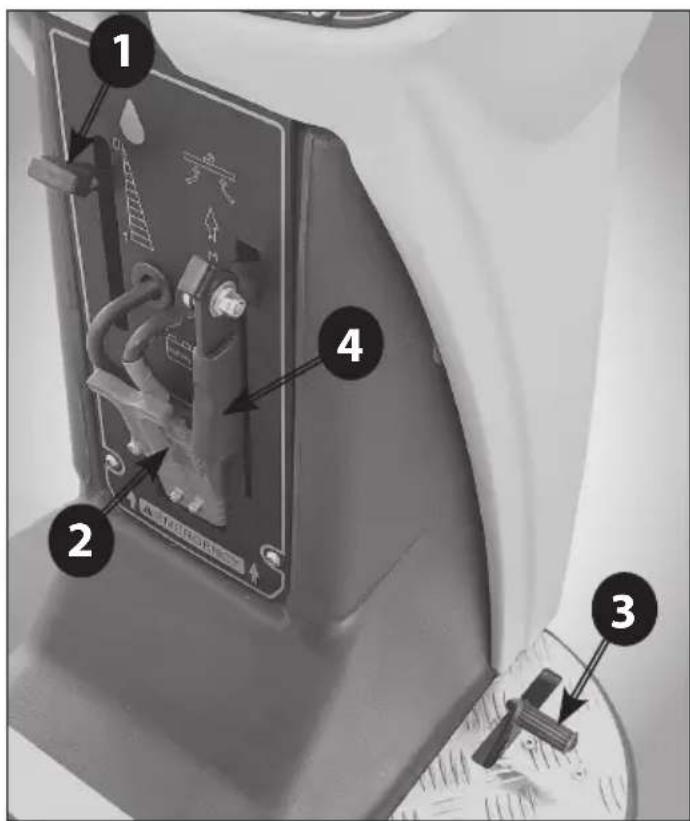
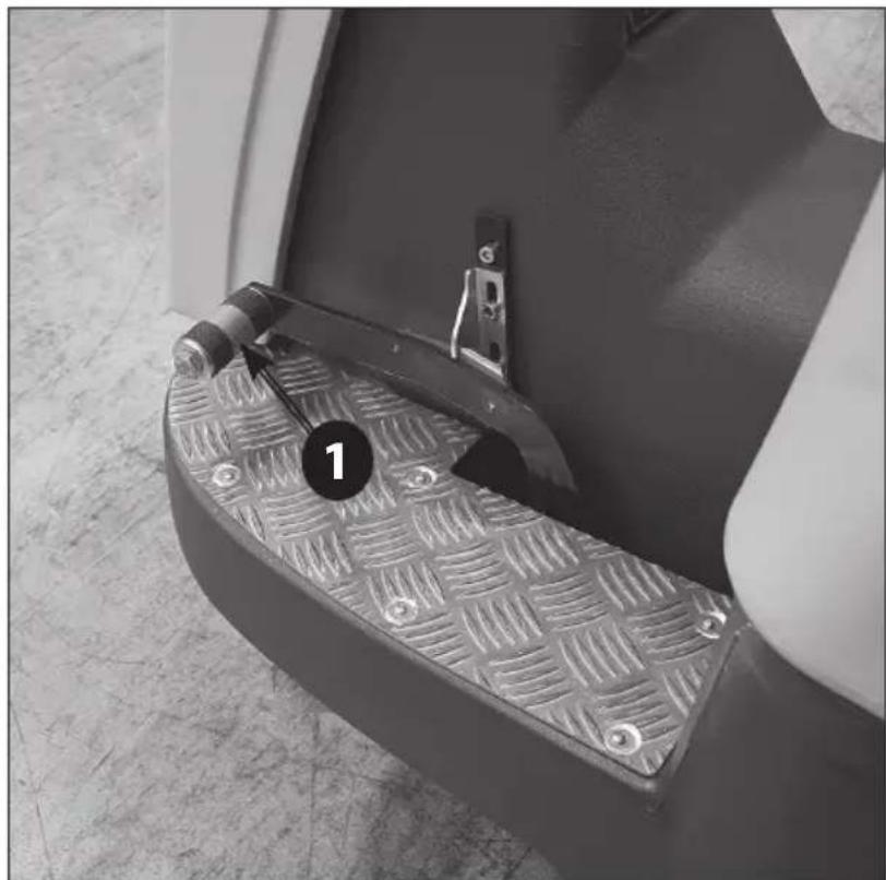
3.4. UNBLOCKING THE ELECTROMECHANICAL BRAKE
⚠ When the machine is switched off or without batteries the electromechanical brake is bloc- king the machine and it is not possible to move it.
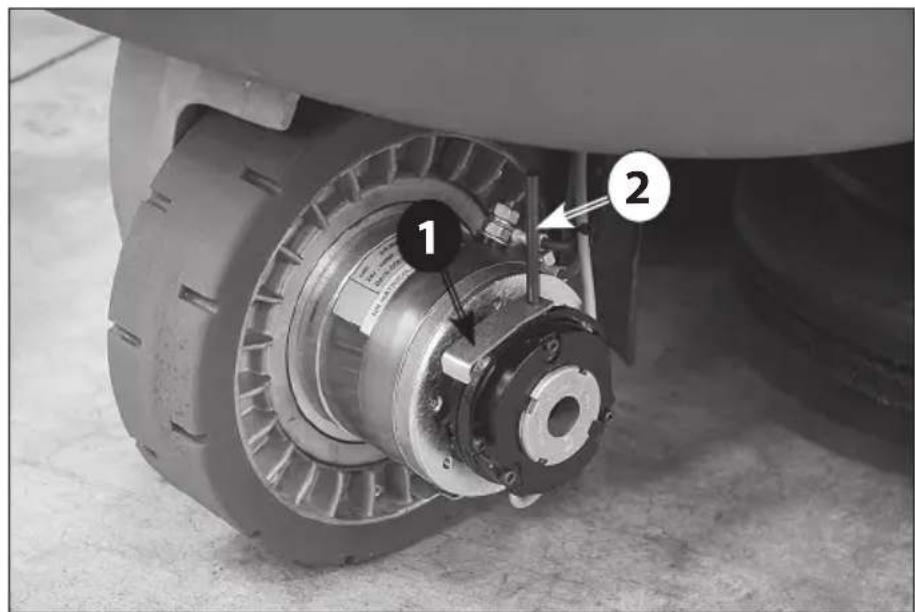
To unblock the electromechanical brake it is necessary to operate on the traction motor in the front wheel (Photo L1 - 2) following the procedure mentioned here below:
- Screw the pin (Photo L2 - 2) and the unblocking lever (Photo L2 - 1) in the fork seating (Photo L1 - 1)
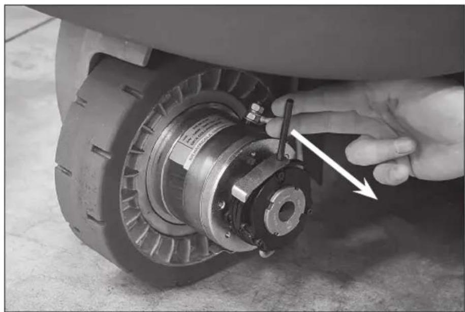
- Pull the pin outwards (Photo L3)
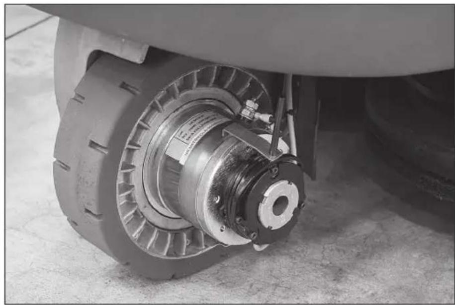
- Rotate the lever towards the motor (Photo L4)
- Block the lever on the motor in order that the fork lever (Photo L1 - 1) will be fixed in the outer position (Photo L5).
Once the machine have been moved, it is necessary to carry out the same procedure on the contrary in order to replace the fork lever in the machine working position (Photo L1 - 1).
Remove the pin and lever
WARNING: Before using the machine be sure that the fork lever is in the machine working position (Photo L1 - 1).
3.5. LIFTING AND TRANSPORT: MACHINE, BATTERY AND BATTERY CHARGER
⚠️ Never use a forklift truck to lift the machine. There are no places on the frame that can be used to lift the machine directly.
Before preparing the packing and transporting the machine:
- Empty the recovery tank and the detergent solution tank.
- Disassemble the squeegee and the brushes or pad drivers.
- Disconnect and remove the batteries.
Place the machine on the original pallet (or an equivalent one that can bear the weight and is big enough for the machine's overall dimensions) using an inclined surface.
Solidly anchor the machine and the squeegee to the pallet using metallic brackets or other elements that can bear the weight of the parts.
Lift the pallet with the machine and load it on the transport vehicle.
Secure the machine and the pallet using ropes connected to the transport vehicle.
As an alternative, when using private transport vehicles, use inclined ramps to push the machine without the pallet, making sure to protect all parts and the machine itself against violent impacts, humidity, vibrations and accidental movements during transport. The battery boxes have holes where tools can be hooked for handling.
To lift or insert the battery (into the machine compartment), use only suitable personnel and equipment (cables, eyehooks, etc.) for the operation and to bear the weight of the loads involved. When transporting, take the same precautions and follow the same instructions provided for the machine together with those in the special manufacturer's manual.
The battery charger can be transported on its supports, both vertically and horizontally. Take the same precautions and follow the same instructions provided for the machine together with those in the special manufacturer's manual.
4. TECHNICAL INFORMATIONS
4.1. GENERAL DESCRIPTION
4.1.1. BATTERY
Regardless of the type of construction, battery performances are indicated with the term capacity, which always refers to a discharge period. Another important value is the number of possible discharges. The capacity is expressed in amps per hour (Ah), while the discharge period is generally indicated as 20 hours (C20 or 20h, or not expressly indicated) or 5 hours (C5 or 5h). The discharge/charge cycles indicate the number of times that the battery can hold a charge under the best conditions, i.e. they indicate the useful battery service life complying with all the necessary measures.
Therefore, the capacity of a battery varies depending on how fast it uses energy (current). That's why there's such a variation in the capacity values expressed as C5 or C20. These factors must be taken into account when comparing products available on the market with our own.
This machine can be equipped with two types of batteries that differ in terms of their construction and features.
- Pb-Acid battery with tubular armoured modules: the electrolyte level in each element must be periodically checked!
⚠️ If one element is no longer covered by the acid solution it will oxidise in 24 hours, thus permanently affecting that element's performance.
Refer to the battery manual to avoid physical damage and economic loss.
- Gel module battery: this type of battery is maintenance free and does not require special environments for recharging (since it does not emit any harmful gases); therefore, it is highly recommended.
⚠ It should not be taken for granted that batteries and battery chargers with the same technical features as those we offer will produce the same results. Only perfect compatibility between these elements
(Pb-Acid batteries, gel batteries and battery chargers) will safeguard the performances, the service life, the safety and the economic value invested.
4.1.2. BATTERY CHARGER
This type of high-frequency battery charger efficiently charges batteries, extending their operating and service life. In addition, because they can be configured, it is a very versatile solution; the same battery charger can be used for both Pb-Acid batteries and for gel batteries.
⚠ It should not be taken for granted that batteries and battery chargers with the same technical features as those we offer will produce the same results. Only perfect compatibility between these elements (Pb-Acid batteries, gel batteries and battery chargers) will safeguard the performances, the service life, the safety and the economic value invested.
4.2. STRUCTURE AND FUNCTIONS
4.2.1. MACHINE
Photo A
1 Recovery tank
2 Operator's seat
3 Solution tank
4 Rear wheel
5 Bumper wheel
6 Splash guard
9 Steering wheel
7 Front steering motorwheel
8 Compartment for electric components
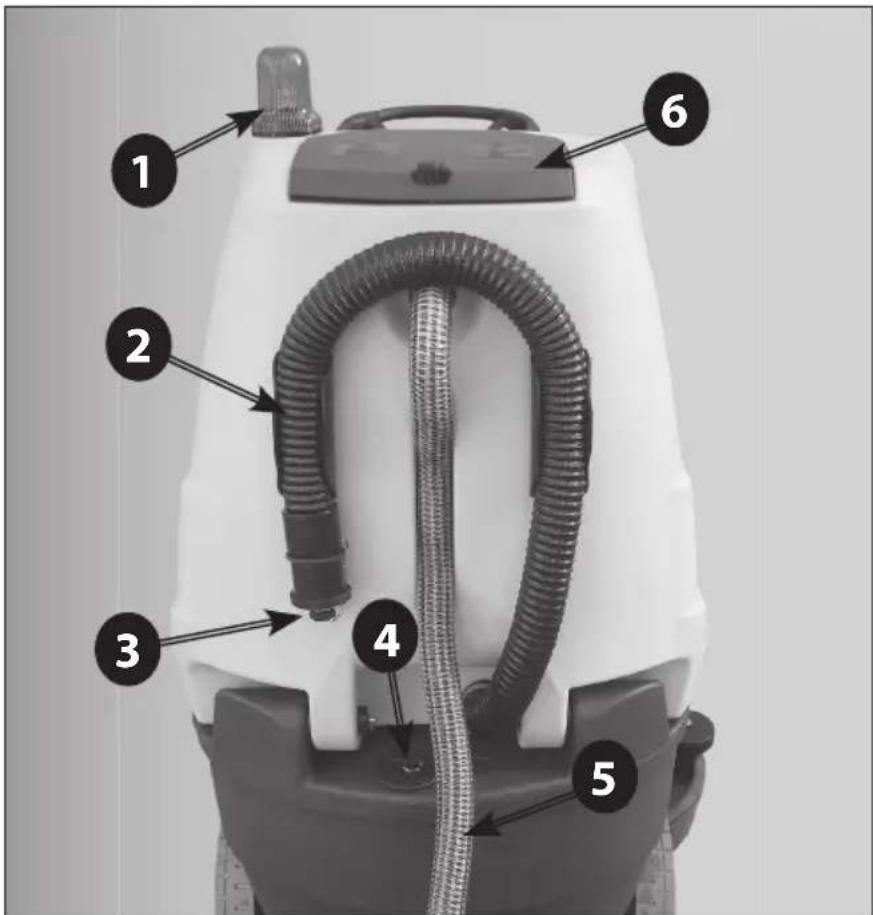
Photo B
1 Blinker
2 Recovery water tank drain hose
3 Recovery water tank drain hose plug
4 Solution water tank filler plug
5 Suction hose
6 Rear cover of the suction compartment
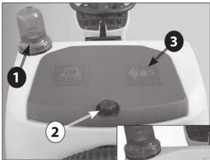
Photo C
1 Blinker
2 Opening knob of the suction compartment
3 Rear cover of the suction compartment
4 Suction motor compartment
5 Suction filter
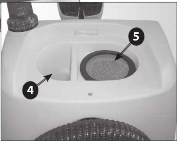
Photo D
1 Solution water tank drain valve
Photo E
1 Squeegee bumper wheels
2 Squeegee pressure adjusting knob
3 Squeegee fast fixing knob
4 Squeegee inclination adjusting knob
5 Suction hose
6 Squeegee blades replacement knobs
7 Squeegee wheels
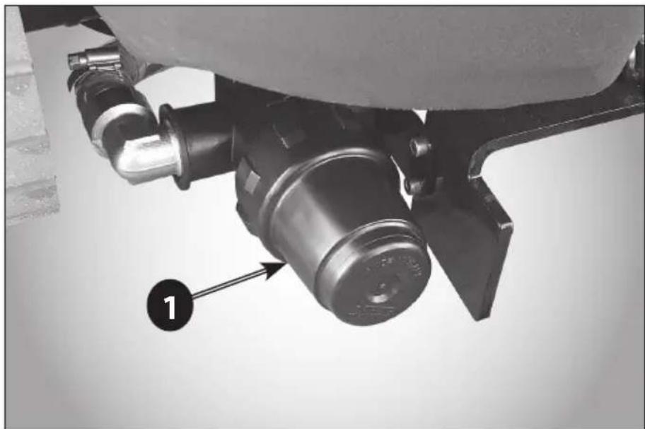
Photo F
1 Solution water filter
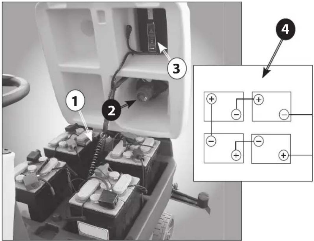
Photo G
1 Battery compartment with 6V batteries
2 Suction motor
3 On-board battery charger
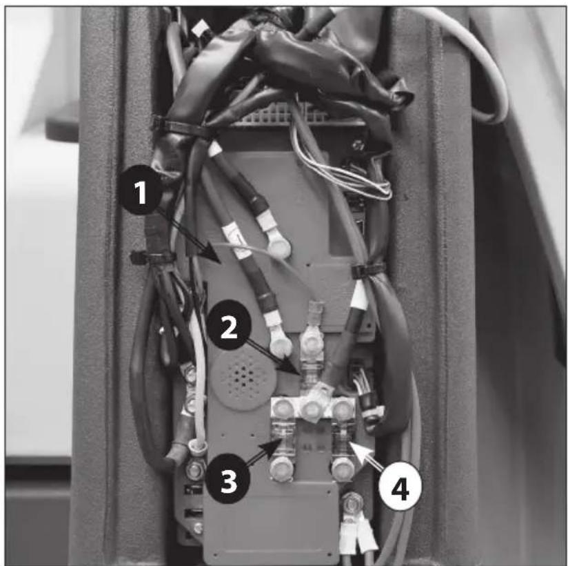
Photo H
1 Chopper control board
2 Traction motor fuse
3 Suction motor fuse
4 Brush motor fuse
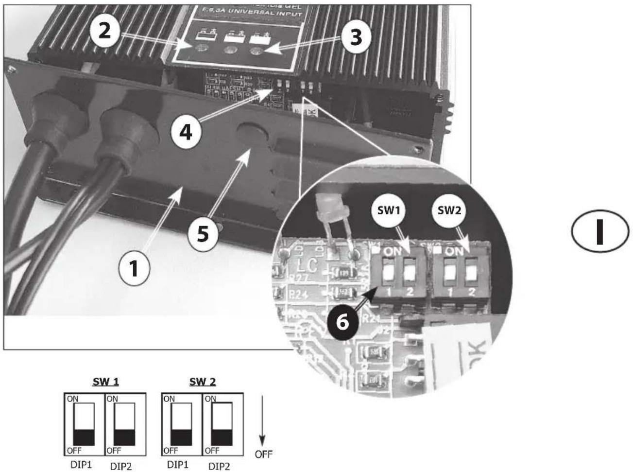
Photo I
1 Battery charger cover
2 Red LED - Battery discharged
3 Green LED - Full charged battery
4 Dip-Switches
5 Plastic cap to access the Dip-Switches
6 Dip-Switches for PB-Acid/GEL battery setting
7 Table with Dip-Switch settings for
PB-Acid/GEL charging curve
Photo L1
1 Electromechanical brake fork lever
Photo L2
1 Unblocking lever
2 Pin
Photo L3 - L4 - L5
Electromechanical brake unblocking procedure
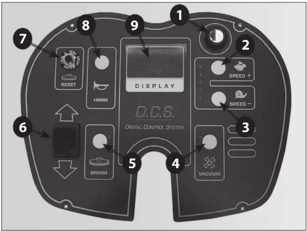
Photo M
1 Key switch
2 Traction speed increase push button
3 Traction speed reduce push button
4 Suction motor operating push button
Squeegee lifting/lowering
5 Brush motor operating push button
Brush plate lifting/lowering
(UP / Plus)
6 Forward/reverse traction selector
7 Brush motor thermal breaker
8 Electric horn
9 Operating informations display
(UP / Plus)
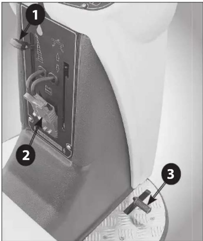
Photo N (UP / Plus)
1 Solution water dosing lever
2 Battery connector
3 Accelerator pedal
Photo O (Essential/Vantage)
1 Solution water dosing lever
2 Battery connector
3 Traction operating pedal
4 Squeegee lifting/lowering lever
Photo P (Essential/Vantage)
1 Brush plate unit lifting/lowering pedal
4.2.2. BATTERY
If supplied, the Pb-Acid (if not dry charged) or gel batteries are ready to be installed:
Positive pole - red
Negative pole - black.
4.3. BATTERY CHARGER CONFIGURATION
⚠️ We recommend to call the assistance centre or a technician if you have problems with the setting given. The machine is equipped with a battery charger configured for PB-Acid batteries
If the operator whish to use GEL / AFGM batteries, it is necessary change the battery charger settings as follows:
⚠️ DISPLAY OF THE BATTERY CHARGER SETTINGS
The battery charger settings are shown by the blinking of the LED indicator when the battery charger is switching on:
- the RED LED indicator (Photo I - 2) flashes 2 times = the battery charger is set for PB-Acid batteries
- the GREEN LED indicator (Photo I - 3) flashes 2 times = the battery charger is set for GEL batteries
The battery charger settings will be displayed even if batteries are not connected.
⚠️ DIP-SWITCH CONFIGURATION FOR BATTERY CHARGER CBHD2 24V 20A
To set the charging curve type for Pb-Acid or GEL/AGM batteries it is necessary to operate on the dip-switches placed inside the battery charger (Photo I-4).
The dip-switches for the setting of the charging curve are on the control card (Photo I - 4) that is placed behind the lower panel of the battery charger (Photo I - 1). It is also possible to reach the dip-switches by removing the plastic cap (Photo I - 5).
For the setting of the charging curve it is necessary to operate on the dip-switches of the group indicated as SW1 (Photo I - 6), placing them as shown in the table (Photo I - 6) at page 7.
NOTE: The dip-switches of the group indicated as SW2 must always be set in the OFF position.
Refer to the relevant manufacturer's manual provided.
4.4. ACCESSORIES
Your machine supplier can provide a complete and updated list of all available accessories, such as brushes, pad drivers, disks, etc.
5. INSTALLATION INFORMATION
5.1. BATTERY PREPARATION
The technical features of the batteries used must match those indicated in the technical features section. Using different batteries may cause serious damage to the machine or may require them to be charged more frequently.
During installation or when performing any type of battery maintenance, the operator must be equipped with adequate safety accessories to prevent accidents. Work far from open flames, do not short-circuit the battery poles, do not generate sparks and do not smoke.
The batteries are normally supplied full of acid solution (for the Pb-Acid type) and ready for use. In any case, follow the steps indicated in the manual supplied with the battery and carefully follow the instructions regarding safety and operating procedures.
5.2. BATTERY INSTALLATION AND PREPARATION
⚠️ These operations must be carried out by specialised personnel.
Make sure the two tanks are empty. If not, empty them in accordance with the specific procedure.
Lift the recovery tank by 90^ , making sure it is stable in that position. This provides access to the battery compartment from the top.
Disconnect the Anderson connector of the battery wiring from the Anderson connector of the machine wiring. Always hold the connectors with the hands and never pull on the cables.
Attach the battery wiring to the battery, connecting the terminals only on the poles marked with the same symbol (red wiring “+”, black wiring “-”)! A battery short-circuit may cause an explosion! Run the cables toward the wiring outlet opening (on one side of the box, only for Pb-Acid batteries), tighten the terminals at the poles and cover them with Vaseline.
Insert the battery putting the opening in the box (only for the Pb-Acid battery) in a position to run the electric wiring to the connector of the machine wiring.
After checking that all the controls on the panel are in position "0" or at rest, connect the battery connector to the machine connector.
⚠️ Close the battery compartment (lowering the recovery tank) making sure not to crush any wires.
5.3. SETTINGS THROUGH THE CONTROL PANEL
When switching on the machine using the key switch (Photo M-1), press simultaneously the BRUSH key (Photo M-5) + SUCTION key (Photo M-4) on the control panel (Photo M).
When the display (Photo M-9) shows "TARATURA???" (CALIBRATION???), also press the SPEED REDUCTION
key (Photo M-3) without leaving the other keys.
When the message "TARATURA" (CALIBRATION) is shown, release the keys previously pressed.
It is now possible to scroll through the settable parameters pressing the BRUSH key (Photo M-5) and the SUCTION key (Photo M-4):
- TIPO LOGO (LOGO TYPE)
- TIPO BATTERIA (BATTERY TYPE)
- CONTRASTO (DISPLAY CONTRAST)
- LINGUA (LANGUAGE)
- RIT. TASTI (KEYS DELAY)
To select and change the desired parameter, press the SPEED REDUCTION key (Photo M-3). With the BRUSH key (Photo M-5) and the SUCTION key (Photo M-4) it is possible to increase or decrease the set value. To confirm the new value, press the SPEED REDUCTION key (Photo M-3).
To exit the calibration select EXIT, and press the SPEED REDUCTION key (Photo M-3).
MEANING OF SETTABLE PARAMETERS:
LOGO TYPE
BATTERY TYPE
Range: Pb Acid / Gel
CONTRAST
Contrast value for the display.
LANGUAGE
Language that is displayed. In this version are available: ITALIAN, FRENCH, ENGLISH, GERMAN, SPANISH.
KEYS DELAY
Delay in hundredths of second between the acceptance of consecutive pressures of the keys. Established to limit communication problems.
5.4. MACHINE PREPARATION
⚠️ Before starting to work, wear non-slip shoes, gloves and any other personal protection device indicated by the supplier of the detergent used or considered necessary based on the operating environment.
Do the following before starting to work. Refer to the relative sections for a detailed description of these steps: Check the battery charge level and charge, if necessary. Mount the brushes or scraper disks (with the abrasive disks) that are suitable for the surface and work involved.
Mount the squeegee, check that it is solidly attached and connected to the suction hose and that the drying straps are not too worn.
Make sure that the recovery tank is empty. If not, empty it completely.
Check and completely close the detergent solution release control.
Fill the detergent solution tank with a mix of clean water and non-foaming detergent in an adequate concentration through the rear hole. Leave 7 cm between the mouth of the plug and the level of the liquid.
To avoid risks, become familiar with the machine movements, carrying out test runs on a large surface without obstacles.
To obtain the best results in terms of cleaning and equipment service life, you should do the following simple but important operations:
- Identify the work area, moving all possible obstacles out of the way; if the surface is very extensive, work in contiguous and parallel rectangular areas.
- Choose a straight work trajectory and begin working from the farthest area to avoid passing over areas that have already been cleaned.
Prepare and check the battery charge according to the instructions provided in the specific section.
Detach the battery connector (the one with the handle) from the machine power connector and connect it to the battery charger connector.
⚠ Do not connect the battery charger to the scrubber-drier's main wiring connector.
Hold the connectors with the hands; do not pull them using the cables.
If the machine is equipped with Pb-Acid batteries, charge only in a well-ventilated area, lift the top tank and open the battery plugs.
Follow the steps indicated in the battery manufacturer's operating and safety manual (see the battery maintenance section).
If the machine is equipped with gel batteries (maintenance free), follow the instructions indicated here below.
If the machine is used regularly:
Always keep the batteries connected to the battery charger when the machine is not being used.
If the machine is not used for extended time periods: Charge the battery during the night after the last work period, then disconnect the battery from the battery charger.
Charge the battery during the night before using the machine again.
Intermediate or incomplete charging while working should be avoided.
If the machine is equipped with Pb-Acid batteries, use a hydrometer to check the element liquid intensity on a regular basis: if one or more elements are discharged and the others fully charged, the battery has been damaged and should be replaced or repaired (refer to the battery service manual).
Close the element plugs and lower the top tank.
Hold the connectors with the hands; don't pull them using the cables.
Reconnect the battery connector to the connector on the machine.
6.2. SQUEEGEE AND SPLASH GUARD ASSEMBLY, DISASSEMBLY AND ADJUSTMENT
The squeegee is the main component that ensures perfect drying.
6.2.1. SQUEEGEE ASSEMBLY
Lower the lifting system to avoid having to keep the body raised while completing connections.
Loosen the connection knobs on the squeegee support (Photo E - 3).
Insert the openings of the squeegee body in the brackets of the oscillating support.
Fully tighten the squeegee knobs of the support (Photo E - 3) in order to block the squeegee on the support.
Firmly insert the machine suction hose into the squeegee body (Photo E - 5).
6.2.2. SQUEEGEE DISASSEMBLY
Lower the lifting system to avoid having to keep the body raised while completing connections.
Disconnect the suction hose from the squeegee body (Photo E - 5).
Loosen the connections connection knobs on the squeegee support (Photo E - 3).
Pull back the squeegee body to detach it from the brackets of the oscillating support.
6.2.3. SQUEEGEE BLADES DISASSEMBLY/ASSEMBLY
Disassemble the squeegee from its support (see 7.2.2)
Unscrew the knobs (Photo E - 6), remove the bolts and the metal bar holders of the squeegee blades. Remove the rubber blades from the squeegee body. To assemble the new blades, place the metal bar holders on the front blade; place them on the squeegee body and insert the bolts in the holes of the squeegee body. Place the rear blade on the squeegee body with the the bolts in its holes; place the metal bar holders and block the blades screwing the fixing knobs (Photo E - 6).
It's normal that the rear strap has to be extended to centre the connection screws. This will bring it under the correct tension to avoid folds on the floor and dry correctly.
6.2.4. SQUEEGEE ADJUSTMENT
The knob screw on the squeegee support (Photo E-4) adjust the squeegee's inclination with respect to the floor. The two screws on the sides, connected to the rear wheels of the squeegee (Photo E - 6), are to adjust the pressure of the squeegee to the floor.
When the squeegee is perfectly adjusted, the rear squeegee blade, sliding as it moves, bends in all points forming an angle of 45^ with the floor.
As the machine operates (advances), it is possible to operate on the inclination knob and pressure screws (Photo E-4; Photo E-6) to adjust the inclination and pressure of the squeegee blades on the floor.
Squeegee drying must be uniform along the entire drying line: damp patches mean that drying is insufficient; turn the adjustment knobs to optimise drying.
6.2.5. SPLASH GUARD ASSEMBLY/ DISASSEMBLY
The splash guard is assembled to the brush plate (Photo A-6) with a spring holder linked to the brush plate itself. To disassemble the splash guard simply detach the spring holder and pull the splash guard.
To reassemble, fix the splash guard in the brush plate, and then hook the steel cable to one side of the plate and the spring holder to the other side of the brush plate.
6.3. ACCESSORY ASSEMBLY/DISASSEMBLY (BRUSHES, PAD DRIVERS AND ABRASIVE DISKS)
⚠️ Never use the machine if brushes or pad drivers and abrasive disks are not perfectly installed.
Assembly:
Make sure that the brush plate is raised; otherwise lift it by following the instructions provided in the specific section.
Make sure that the ignition key on the control panel is in position "0".
Bring the brushes (or the guide disks equipped with abrasive disks) near the connections, under the brush plate; lift them, bring them through the centering flange, and turn them opposite the rotation direction until you hear the stable "click" connection.
⚠️ Do not allow the length of the rows of brushes to become lower than 1 cm.
⚠ Do not allow the thickness of the abrasive disks to become less than 1 cm.
Working with excessively worn brushes or excessively thin abrasive disks may damage the machine and the floor.
Regularly check the wear on these parts before starting to work.
Disassembly or replacement:
Make sure that the brush plate is raised; otherwise lift it by following the instructions provided in the specific section.
Make sure that the ignition key on the control panel is in position "0".
While holding the brushes (or the guide disks) with the hands under the plate, turn them in the rotation
direction while lowering to release them from the guide plate.
6.4. FILLING AND DRAINING THE DETERGENT SOLUTION TANK
The temperature of the water or the detergent should never exceed 50^ C.
Always empty the detergent solution tank before filling it up.
To fill the solution tank:
- Remove the plug in the back of the machine.
- Leave 7 cm between the mouth of the plug and the liquid level. Do not fill beyond this point!
- Add the required quantity of the chemical product, considering the percentage indicated by the supplier, with reference to the full tank capacity listed on the product sheet.
- Use only those products suitable for the floor and the dirt to be removed.
The machine was designed to be used with non-foaming and biodegradable detergents made specifically for scrubber-driers. The use of other chemical products (such as sodium hypochlorite, oxidisers, solvents or hydrocarbons) may damage or destroy the machine.
- Follow the safety regulations specified in the relative section and indicated on the detergent container.
- Contact the machine manufacturer to obtain a complete list of available and suitable detergents.
• Always add the detergent after filling the tank with water to prevent foam from being created inside. - Do not leave the water hose unattended and insert it completely into the tank: the hose might move and get sensitive parts of the machine wet.
- Close the tank cover.
To drain the solution water tank:
- Open the valve located at the bottom of the machine in the back (Photo D - 1) and wait until the tank has been completely emptied.
- Close the drain valve.
6.5. DRAINING THE RECOVERY TANK
The dirty water must be drained in accordance with national regulations.
The user is completely responsible for ensuring compliance with such rules.
After the detergent solution is finished, always empty the recovery tank before filling it again.
In general, the recovery tank can be emptied whenever required, and even during intermediate phases of the work cycle.
Always empty the recovery tank before lifting it to avoid health problems for operators and to avoid damaging the machine.
The recovery tank volume is higher than the detergent solution volume, therefore a potentially dangerous situation for the suction motor should never
occur. In any case, a safety float turns off the suction motor if the dirty liquid level is too high.
If water or foam starts leaking from under the tanks for any reason, immediately turn off the suction motor and empty the recovery tank.
To drain the tank:
Drive the machine to a suitable location to drain the dirty water and preferably near a toilet or a sewer drain (comply with the national regulations for waste water disposal).
Turn off the machine and remove the key from the panel.
Detach the drain hose from the hook and, keeping it high, unscrew the plug.
Lower the drain hose toward the selected drainage point.
The emptying operation can be interrupted quickly and whenever required just by raising the drain hose. Check the quantity of residual dirt in the tank and, if necessary, clean the interior through the inspection hole, lifting the cover and the funnel at the top.
Carefully position the funnel inside the inspection hole and close the top cover, tightening the lock handles after each inspection/cleaning operation.
Fully tighten the drain hose with the screw plug and hang it on the support behind the machine.
The top cover of the tank and the drain hose plug must be airtight, otherwise the subsequent pressure loss will reduce drying efficiency.
6.6. DRIVING THE MACHINE
Select the running direction using the Forward/Reverse selector.
Insert and turn the ignition key.
Using the right foot lightly press the accelerator pedal and drive the machine to its destination.
Turn off the machine and remove the keys from the control panel.
The running direction can be changed using the forward/reverse selector, even while pressing on the accelerator pedal.
6.7. WORK METHOD
6.7.1. PREPARATION AND WARNINGS
Remove any loose solid residue from the surface to be treated (using suitable tools, such as vacuum cleaners, sweepers, etc.). It this is not done, the solid dirt might prevent the squeegee from operating correctly, reducing drying efficiency.
This machine can driven only by trained personnel.
6.7.2. DIRECT SCRUBBING OR FOR SLIGHTLY DIRTY SURFACES
Scrubbing and drying in a single pass.
Prepare the machine as previously described.
Select the forward direction using the direction lever.
Insert and turn the key.
Activate the suction motor, the brush motor and the detergent solution supply.
Lower the brushes and the squeegee.
Use the detergent adjustment lever to regulate the solution outlet flow (depending on advancement speed).
Lightly press the advancement pedal and check that all systems are working.
Fully depress the accelerator to increase the work speed.
Adjust the maximum advancement speed and the detergent solution flow as required.
The steering wheel is similar to a car steering wheel: it can be used to turn the machine around itself by steering all the way to one side. § During these operations, the rear of the machine moves slightly outward: reduce the speed to avoid brusque direction changes and impacts against walls or other objects.
To avoid damage to the surfaces being treated, the brush motor will stop automatically about 2 seconds after the advancement pedal has been completely released.
Never use the machine without the detergent solution: the floor might be damaged.
6.7.3. INDIRECT SCRUBBING OR FOR VERY DIRTY SURFACES
Scrubbing and drying in various passes.
Prepare the machine as previously described.
First set of operations:
Select the forward direction using the direction lever. Insert and turn the key.
Activate the brush motor and the detergent solution supply.
Lower the brushes.
Use the detergent adjustment lever to regulate the solution outlet flow (depending on advancement speed).
Lightly press the advancement pedal and check that the brushes and solution feed system are working.
Fully depress the accelerator to increase the work speed.
Adjust the maximum advancement speed and the detergent solution flow as required.
The steering wheel is similar to a car steering wheel: it can be used to turn the machine around itself by steering all the way to one side.
- During these operations, the rear of the machine moves slightly outward: reduce the speed to avoid brusque direction changes and impacts against walls or other objects.
Allow the detergent solution to work on the dirt according to what is indicated in the information relative to the detergent used.
Second set of operations:
Follow the steps described in the previous section
"Direct Scrubbing" (7.8.3).
To avoid damage to the surfaces being treated, the brush motor will stop automatically about 2 seconds after the advancement pedal has been completely released.
When moving in reverse, the squeegee will lift and suction will be deactivated automatically. After changing direction (forward direction), the squeegee and the suction will automatically return to their previous condition.
Never use the machine without the detergent solution: the floor might be damaged
6.7.4. POST-SCRUBBING OPERATIONS
Cut off the supply of detergent.
Lift the brush unit and turn off the brush motor.
After having completely dried any traces of water on the surface, wait a few seconds and then lift the squeegee and turn off the suction motor.
Move to a suitable location to drain the tanks (as described in 7.4 and 7.5).
Empty and clean the tanks (see sections 7.4 and 7.5).
Turn off the machine using the key and remove it from the control panel.
If necessary, charge the battery (see the relative section).
6.8. INFORMATIONS ABOUT THE USE OF MODEL (UP / Plus)
The model (UP / Plus) is equipped with electric actuators for the automatic lifting/ lowering of the brush group unit and of the squeegee.
The lifting/ lowering of the brush group unit can be effected through the selector positioned on the control panel (Photo M - 5) and takes place simultaneously to the switching on/off the brush motor; the lifting/ lowering of the squeegee can be effected through the selector positioned on the control panel (Photo M - 4) and takes place simultaneously to the switching on/off the suction motor.
When moving in reverse, the squeegee will lift automatically in order to avoid to damage itself. After changing direction (forward direction), the squeegee will automatically return to their previous condition.
7. MAINTENANCE INFORMATION
Turn the key, remove it from the control panel and disconnect the battery from the machine wiring.
All work on the electrical system as well as all maintenance and repair operations (especially those not explicitly described in this manual) should be carried out only by authorised service centres or by specialised technical personnel who are experts in the sector and in the pertinent safety regulations.
Performing regular maintenance on the machine, and carefully following the manufacturer's instructions,
is the best guarantee for obtaining the best performances and extended machine service life.
7.1. TANKS
Drain the two tanks as described in the relative sections.
Remove any solid dirt by filling and draining the tanks until all dirt has been eliminated: use a washing hose or similar tool to do this.
⚠️ Water hotter than 50°, a high-pressure cleaner or excessively powerful sprays may damage the tanks and the machine.
Leave the covers of the tanks open (only while the machine is not being used) so that they can dry and thus prevent the formation of foul odours.
7.2. SUCTION HOSE
Detach the suction hose from the squeegee.
Pull out the suction hose from its connection hole placed in the recovery tank.
Now you can wash the hose and remove any obstructions.
After the cleaning, firmly insert again the suction hose inside connection hole placed in the recovery tank.
Firmly insert the hose on the squeegee body.
7.3. SQUEEGEE
⚠ Do not handle the squeegee with bare hands: wear gloves and any safety clothing needed to carry out the operation.
Detach the squeegee from the machine and clean it under running water using a sponge or a brush.
Check the efficiency and the wear on the strips in contact with the floor. They are designed to scrape the film of detergent and water on the floor and to isolate that portion of the surface to enhance the vacuum of the suction motor: this ensures that the machine will dry very efficiently. Working constantly in this manner tends to round or to deteriorate the sharp edge of the strip, thus reducing drying efficiently. This is why the squeegee strips must be replaced.
To replace the worn straps, follow the instructions in the relative section. Turn the straps around to wear down the other sharp corners or to install new ones.
7.4. ACCESSORIES
Remove and clean the brushes or the scraper disks.
⚠ To avoid damaging the floor and the machine, carefully check if foreign matter, such as metallic parts, screws, chips, cords or similar items, has become jammed.
Check that the brushes are flat as they work on the surface (check for any irregular wear on the brushes or on the abrasive disks). If necessary, adjust the slant of the action on the floor.
Use only the accessories recommended by the manufacturer: other products may reduce operating safety.
7.5. CLEANING SOLUTION FILTER
Make sure that the detergent solution tank is empty. Check and clean the solution filter located in the lower front part of the machine. Clean with running water if necessary and check that the detergent solution is being delivered on the brushes.
Fully tighten the filter to prevent leaks during operation.
7.6. MACHINE BODY
Use a sponge or a soft cloth to clean the exterior of the machine and, if necessary, a soft brush to eliminate tough dirt. The machine's shockproof surface is rough to make it harder to see scratches caused during use. However, this does not make it easier to remove tough stains on the surface. Steam machines can be used but it's prohibited to use hoses with running water or a high-pressure cleaner.
7.7. BATTERIES
PB-ACID
Carry out maintenance operations in accordance with the manufacturer's instructions and with all the other instructions provided in this manual.
Exposing the element plates (not completely immersed in the acid solution) will lead to rapid oxidation and irreparably reduce the element's operating capacities.
An overflowing acid solution may corrode the machine. Use battery chargers recommended by the manufacturer and, in any case, those that are suitable for the type of battery to be charged.
Always charge batteries in well-ventilated rooms: there is an explosion risk!
The use of gel or maintenance-free batteries is highly recommended.
GEL
Carry out maintenance operations in accordance with the manufacturer's instructions and with all the other instructions provided in this manual.
Use only those battery chargers recommended by the manufacturer.
If the batteries are not used, in either case, for an extended period of time, disconnect them and restore the charge within the time limits specified for the type of battery used (generally and as a precaution, no more than 3 months for Pb-acid/GEL/AGM batteries, 6 months for Li-ion batteries).
The manufacturer accepts no liability for damage to batteries caused by failure to follow this procedure.
7.8. FUSES AND THERMAL BREAKERS
The machine is equipped with electric protection devices on the main operating components to avoid costly malfunctions.
When one of these breakers trips automatically, the disabled function can be reactivated by fully de-
pressing the breaker that tripped.
When the thermal breakers trip, especially when the machine is used during the first few weeks, it might not be caused by actual machine malfun- ctons. However, a specialised technician should check the device if the relative breaker continues to trip.
7.9. PERIODIC MAINTENANCE
For all the operations described in the following scheduled maintenance table, refer to the instructions and detailed warnings in the relative sections.
You'll always be able to use your machine as efficiently as possible by maintaining a stock of the most common consumable materials and by scheduling routine and extraordinary maintenance. Contact your dealer for a list of these spare parts.
8. OPERATING CHECKS
8.1. MALFUNCTIONS SELF-DIAGNOSTIC
The display located on the control panel (Photo M - 9) also has the function of showing any active alarms on the machine concerning to the control board operation; in case of alarm will be shown the code and a brief description of the error.
Here below is the list of error messages with the corresponding diagnostic:
8.2. PROBLEM SOLVING GUIDE
These indications make it easier to understand the underlying causes of some problems based on specific type of inconvenience. For the type of corrective action to take please refer to the specific sections described below.
8.2.1. THE MACHINE DOESN'T WORK
😊 The key is not inserted or incorrectly turned.
😊 Insert and turn the key to position "1".
The battery connector is disconnected or poorly attached to the main wiring connector.
😊 Firmly connect the two connectors.
😊 The emergency/work stoppage button is pressed.
☺ Disengage the emergency/work stoppage button.
😊 The machine is charging.
😊 Complete the charging operation.
😊 The batteries are discharged.
😊 Charge the batteries.
☺ No operator in the driver's seat.
😊 Sit in the driver's seat.
😊 The main fuse is burned.
😊 Replace it.
😊 The control card has overheated.
☑ Check the operating situations that may have caused the malfunction (high slope, etc.). Wait 30 minutes and try to avoid the same incorrect operations. If the problem persists, contact the authorised service centre.
8.2.2. THE MACHINE DOESN'T MOVE FORWARD
😊 The direction selection lever is in the neutral position.
😊 Select a running direction.
☺ The advancement pedal is not pressed.
😊 Press the pedal.
| PROBLEM SOLVING GUIDE | When needed | After every use | Weekly | Monthly |
| Remove and wash the squeegee | X | |||
| Drain the recovery tank | X | |||
| Drain, rinse with clean water or sanificate the recovery tank | X | |||
| Charge the batteries | X | X | ||
| Check the acid level in the battery cells (if batteries are not maintenance-free) | X | |||
| Remove brushes and check for brush wear, foreign bodies and wrapped belts | X | |||
| Verify the machine general conditions. | X | |||
| Verify that suction hose and conduct are free from obstructions | X | |||
| Check the wear of the squeegee rubber blades | X | |||
| Open and clean the solution water filter | X | |||
| Clean the brush plate, squeegee support and squeegee | X | |||
| Check the lifting/lowering of the brush plate. | X | |||
| Check the lifting/lowering of the squeegee. | X | |||
| Grease the moving parts. | X | |||
| Check the control cable for the opening of the solution water tap. | X | |||
| Verify the security devices (emergency switch, mechanical or electromechanical brake, operator safety switch, etc). | X | |||
| Descale water hoses. | X |
😊 The floor slope is too steep.
😊 Manually push the machine to the new level.
😊The thermal breaker of the drive motor is tripped.
☺ Stop the machine, allow it to remain inactive for 5 minutes, replace the fuses.
☺ The advancement pedal microswitch is broken.
😊 Replace it.
😊 The batteries are dead.
😊 Charge the batteries.
😊 The accelerator pedal was pressed when the machine was turned on.
😊 Release the accelerator pedal, turn off and restart the machine.
The accelerator pedal potentiometer is malfunctioning.
😊 Replace the potentiometer.
😊 The drive motor was not stopped when the machine was turned on.
😊 Place the machine on a flat surface, turn it on and off again with the key.
8.2.3. THE BRUSHES DON'T ROTATE
😊 The brush motor switch is not selected.
☺ Press the button to activate the brushes.
The machine is not moving forward and the control tripped to avoid damaging the floor.
😊 Press the advancement pedal.
⑧ The brush motor thermal breaker tripped; the motor overheated.
😊 Troubleshoot the cause (cords or similar items that impede movement, surface too rough, etc.) and press the reset breaker.
☺ The transmission belt is broken.
😊 Replace it.
😊 The motor relay or the brush motor is broken.
😊 Replace it.
8.2.4. NOT ENOUGH OR TOO MUCH DETERGENT
😊 The detergent solution tank is empty.
😊 Fill the detergent solution tank after having emp - tied the recovery tank.
| Message displayed Solution | |
| {"01 TRACTION#BLOCKAGE"} | Stops traction motor to protect from excessive current peak. To restore, restart the machine. |
| {"02 MAX TRACTION#TEMPERATURE"} | Stops traction to protect the motor from excessive continuous current. To restore, restart the machine after the motor has cooled down. |
| {"03 BATTERY SPENT"} | Stops brush, suction and traction motor due to battery voltage insufficient. To restore, restart the machine after the battery charging. |
| {"04 MAX ELECTR#TEMPERATURE"} | Stops traction motor due to excessive temperature of the electronic control board unit. To restore, restart the machine after the control board has cooled down. |
| {"05 BATTERY LEVEL#TOO HIGH"} | Stops brush, suction and traction motor due to excessive battery voltage. To re-store, restart the machine after having checked the battery. |
| {"06 ACCELERATOR#PEDAL FAULT"} | Stops traction for incorrect communication with the potentiometer (suspect detachment). To restore, restart the machine after having checked the correct connection of the potentiometer. |
| {"07 ERROR#TEMPERATURE"} | The traction speed is reduced according to the setted value of the parameter RID_TEMP. To restore proceed at reduced speed until the cooling of the electronic control board unit. |
| {"08 BATTERY LEVEL#VERY LOW"} | Stops brush and suction motor due to battery voltage insufficient. To restore, re-start the machine after the battery charging. |
| {"09 BATTERY LEVEL#LOW"} | Stops brush motor due to battery voltage insufficient. To restore, restart the machine after the battery charging. |
| {"10 TANK FULL"} | Stops suction motor because the recovery water tank is full. To restore, empty the recovery tank. |
| {"11 START#BLOCKAGE"} | Stops traction as the accelerator pedal is pressed down when turning on the machine or after braking, avoiding unwanted movements of the machine. To restore, fully release the accelerator pedal. |
| {"12 RECOVERY TANK#EMPTY"} | Indicates that the solution water tank is empty. To restore, it is necessary to fill the solution water tank. |
| {"19 SQUEEGEE#LOWERED"} | In reverse gear indicates that the squeegee has remained lowered (Essential model). To restore, lift manually the squeegee with the control lever. |
| {"20 COMUNICATION#ERROR"} | Interrupted communication between the control panel keyboard and the control board. Turn off the machine and verify the integrity of the connections and try again. |
The brushes or the machine has stopped.
😊 Activate the brushes and press the accelerator.
😊 The flow adjustment lever is closed or almost closed.
😊 Adjust/increase the detergent solution outlet flow as required.
😊 The detergent solution filter is clogged.
😊 Clean the filter.
The detergent feed conduit is clogged in some point.
😊 Clean out the conduit by removing the dirt.
☺ The flow opening solenoid valve is burned.
😊 Replace it.
8.2.5. NO SUCTION
😊 The suction hose is not connected to the squeegee.
😊 Connect it correctly.
😊 The suction hose, the squeegee conduit or the inspection compartment is clogged.
Clean out and remove any obstructions from the conduits.
😊 The suction motor is turned off.
😊 Activate it.
😊 The recovery tank is full.
😊 Empty it.
😊 The suction motor is not receiving electric power or is burned.
😊 Check the connections and, for the latter case, replace the motor.
8.2.6. INSUFFICIENT SUCTION
☺ The recovery tank cover was not correctly tightened.
😊 Tighten it correctly.
😊 The recovery tank drain hose plug is not perfectly closed.
😊 Close it correctly.
😊 The suction hose, the squeegee conduit or the inspection compartment is clogged.
😊 Clean out and remove any obstructions from the conduits.
8.2.7. THE BRUSH MOTOR OR THE SUCTION MOTOR DOESN'T STOP
😊 The relay switch is defective.
Stop the machine, cutting off the main power supply and disconnecting the main battery connector, and contact the technical service centre.
8.2.8. THE SQUEEGEE DOESN'T CLEAN OR DRY EFFICIENTLY
😊 The squeegee blades are worn or are dragging solid dirt.
😊 Replace or clean them.
The squeegee adjustment is not correct; the advancement must be exactly perpendicular to the running direction.
😊 Adjust the squeegee.
😊 The suction hose, the squeegee conduit or the inspection compartment is clogged.
😊 Clean out and remove any obstructions from the conduits.
8.2.9. THE BATTERY CHARGER DOESN'T WORK
😊 The battery charge doesn't start.
😊 Check that the battery charger is connected to the battery. Consult the battery charger manual.
8.2.10. THE BATTERIES DO NOT CHARGE OR DO NOT HOLD A CHARGE
At the end of the charging process, the battery is not correctly charged (see the battery manufacturer's instruction-maintenance manual)
😊 Check the battery charger error message and check the data indicated on the display (see the battery charger's instruction manual).
The batteries are new and do not generate 100% of the rated performances.
😊 The accumulator reaches the maximum performance after 20-30 complete charge cycles.
😊 The electrolyte has evaporated and does not completely cover the plates.
😊 Check the battery manufacturer's use and maintenance manual.
😊 There are significant differences in density among the various elements.
😊 Replace the damaged battery.
Always consult the battery and battery charger use and maintenance manual. If this does not solve the problem, contact the authorised technical service centre.
The manufacturer CANNOT solve problems caused by using batteries and battery chargers that were not directly supplied.
9. CONDITIONS OF WARRANTY
All our appliances are subjected to rigorous tests and are covered by warranty against material or manufacturing defects for a period of 12 months. The warranty comes into effect from the date of purchase. The date of purchase is the date indicated on the receipt issued by the Reseller when the appliance is consigned. The manufacturer shall repair or replace any faulty parts free of charge during the period covered by the warranty. Any defects, which cannot be clearly attributed to material or manufacturing defects shall be examined by one of our Technical Service Centres or at our factory and charged in accordance with the outcome. The following are anyhow not covered by the warranty: accidental damage during transportation or handling, accidental damage caused by negligence or unsuitable conduct, damage due to incorrect or improper uses or installations which do not conform with the warnings included in the instruction manual, and anyhow due to unusual
events which do not depend on the running or use of the appliance. Appliances requiring repair must be delivered at the Technical Service Centre complete with all their original accessories together with proof of purchase. If the appliance has been repaired or tampered with by unauthorised third parties, the warranty shall be considered null and void. The warranty shall also be considered null and void if the user is not able to produce an original (legible and complete) document proving purchase or if it not possible to read the appliance serial number located on the frame. The appliance shall not be replaced and the warranty shall not be extended once the appliance has been affected by a fault. Repairs shall be carried out at one of our Authorised technical Service Centres or at our factory. Appliances for repair must be sent carriage free, that is, the user shall pay and be responsible for carriage. The warranty does not cover the cleaning of working parts, any scheduled maintenance nor the repair or replacement of parts subject to normal wear and tear. The manufacturer shall not be held liable for damage to persons or things caused by any installation which does not comply with the instructions in the manual or faulty use of the appliance.
9.1. SCRAPPING OF THE MACHINE
If the machine will no longer be used, remove the batteries and dispose of them in accordance with the eco-compatibility regulations as set forth in European standard 2013/56/EU or deposit them in an authorized collection centre.
To dispose of the machine, comply with the current laws where it is used: - disconnect the machine from the mains and clean it after emptying any liquids; - separate the machine into groups of homogeneous materials (plastics in accordance with the recycling symbol, metals, rubber, packing). For parts containing different materials, contact the competent authorities; Each homogeneous group must be disposed of in accordance with recycling laws. In addition, it is recommended to eliminate those parts of the machine that may be dangerous, especially for children.
9.2. DISPOSAL (WEEE)
As the owner of electrical or electronic equipment, the law (in accordance with the EU Directive 2012/19/EU on waste from elec - trical and electronic equipment and the national laws of the EU Member States that have implemented this Directive) prohibits you from disposing of this product or its electrical / electronic accessories as municipal solid waste and obliges you to make use of the appropriate waste collection facilities. The product can be disposed of by returning it to the distributor when a new product is purchased.
The new product must be equivalent to that being disposed of. Disposing of the product in the environment can cause great harm to the environment itself and human health.
The symbol in the figure indicates the urban waste containers and it is strictly prohibited to dispose of the equipment in these containers. Non-compliance with the regulations stipulated in the Directive 2012/19/EU and the decrees implemented in the various EU Member States is administratively punishable.
FR
TABLE DES MATIÈRES
- GENERALITES
1.1. BUT DU MANUEL
1.2. TERMINOLOGIE ET LEGENDE DES SYMBOLES REDACTIONNELS
1.3. IDENTIFICATION DE LA MACHINE
1.4. USAGE PREVU
1.5. MODIFICATIONS TECHNIQUES
- INFORMATIONS SUR LA SECURITE
2.1. REGLES IMPORTANTES
2.2. EMISSION SONORE ET VIBRATIONS
- INFORMATIONS SUR LA MANUTENTION
3.1. MANUTENTION DE L'EMBALLAGE
3.2. CONTROLE A LA RECEPTION
3.3. DEBALLAGE
3.4. DÉBLOCAGE DU FREIN ÉLECTROMÉCANIQUE
3.5. MANUTENTION DE LA MACHINE, DES BATTERIES ET DU CHARGEUR DE BATTERIES
- INFORMATIONS TECHNIQUES
4.1. DESCRIPTION GENERALE
4.1.1. BATTERIES
4.1.2. CHARGEUR DE BATTERIES
4.2. STRUCTURE ET FONCTIONS
4.2.1. MACHINE
4.2.2. BATTERIES
4.3. CONFIGURATION DU CHARGEUR DE BATTERIE
4.4. ACCESSOIRES
- INFORMATIONS SUR L'INSTALLATION
5.1. PREPARATION DES BATTERIES
5.2. INSTALLATION ET BRANCHEMENT DES BATTERIES
5.3. RÉGLAGES VIA LE PANNEAU DE COMMANDE
5.4. PREPARATION DE LA MACHINE
- INFORMATIONS SUR L'UTILISATION
6.1. RECHARGE DES BATTERIES
6.2. ASSEMBLAGE, DESASSEMBLAGE, REGLAGE DU SUCEUR ET DE LA BAVETTE DE PROTECTION
6.2.1. ASSEMBLAGE DU SUCEUR
6.2.2. DESASSEMBLAGE DU SUCEUR
6.2.3. REMPLACEMENT DES BAVETTES DU SUCEUR
- CONDITIONS DE GARANTIE
9.1. DEMOLITION DE LA MACHINE
9.2. ÉLIMINATION
1. GENERALITES
1.1. BUT DU MANUEL
3. INFORMATIONS SUR LA MANUTENTION
3.1. MANUTENTION DE L'EMBALLAGE
FOTO O (Essential / Vantage)
FOTO P (Essential / Vantage)
Options: Pb acide / Gel
CONTRASTE
- HANDLINGS-INFORMATIONEN
3. HANDLINGS-INFORMATIONEN
FOTO O (Essential / Vantage)
FOTO P (Essential / Vantage)
FOTO O (Essential / Vantage)
FOTO P (Essential / Vantage)
FOTO O (Essential / Vantage)
FOTO P (Essential / Vantage)
Retirar as lâminas de borracha.
8.2.3. FIRÇALAR DÖNMÜYOR
8.2.4. YETERSİZ YA DA ÇOK FAZLA DETERJAN
8.2.5. EMİŞ YOK
8.2.6. EMİŞ GÜCÜ DÜŞÜK
8.2.7. FIRÇA MOTORU VEYA EMME MOTORU DURMUYOR
FOTOĞRAF N (UP / Plus)
FOTOĞRAF O (Essential / Vantage)
FOTOĞRAF P (Essential / Vantage)
8.2.3. FIRÇALAR DÖNMÜYOR
8.2. PROBLEEM OPLOSSING
8.2.1. DE MACHINE WERKT NIET
8.2.2. DE MACHINE VERPLAATST ZICH NIET
8.2.3. DE BORSTEL DRAAIT NIET
8.2.4. NIET GENOEG OF TE VEEL REINIGINGSMIDDEL
FOTO O (Essential / Vantage)
FOTO P (Essential / Vantage)
8.2. PROBLEEM OPLOSSING
FOTO O (Essential / Vantage)
FOTO P (Essential / Vantage)
EN Acoustic pressure
K (uncertainty) ±1dB (A)
Acoustic power measured
Acoustic power granted
Paolo Bucchi (Legal Representative Lavorwash S.p.A.)