Dolphin Pro X2 - Pool MAYTRONICS - Free user manual and instructions
Find the device manual for free Dolphin Pro X2 MAYTRONICS in PDF.

User questions about Dolphin Pro X2 MAYTRONICS
0 question about this device. Answer the ones you know or ask your own.
Ask a new question about this device
Download the instructions for your Pool in PDF format for free! Find your manual Dolphin Pro X2 - MAYTRONICS and take your electronic device back in hand. On this page are published all the documents necessary for the use of your device. Dolphin Pro X2 by MAYTRONICS.
USER MANUAL Dolphin Pro X2 MAYTRONICS
Dolphin PROX 2 Gyro Pool Cleaner
EN Operating Instructions
Dolphin PROX 2 Gyro Pool Cleaner.... p. 1-10
natural_image
Exterior view of a modern office building (no signage)_
-
| _
一
1
EN
Dolphin PROX 2 Gyro Robotic Pool Cleaner
Operating Instructions
Contents
- INTRODUCTION 2
- SPECIFICATIONS 2
- WARNINGS AND CAUTIONS....2
3.1. Warnings....2
3.2. Cautions....2
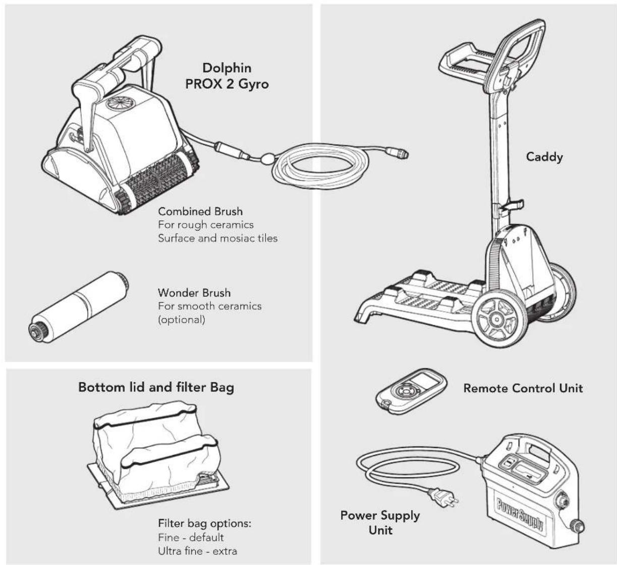
- POOL CLEANER PARTS....3
- USING THE POOL CLEANER....4
5.1. Setup....4
5.2. Putting the Pool Cleaner into the pool....5
5.3. Removing the Pool Cleaner from the pool....5
5.4. Maintenance....6
5.5. Off-season storage 7
- POWER SUPPLY 8
- REMOTE CONTROL UNIT 9
CADDY ASSEMBLY 81
Dolphin PROX 2 Gyro Pool Cleaner
Operating Instructions
1. INTRODUCTION
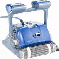
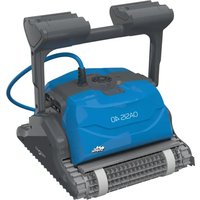
Thank you for purchasing a Maytronics Robotic Pool Cleaner.
We are sure that your Maytronics Robotic Pool Cleaner will provide you with reliable, convenient and cost effective pool cleaning. Its reliable filtration in all pool conditions and all-surface climbing brush enhance maximum pool hygiene.
The Robotic Pool Cleaners by Maytronics deliver advanced cleaning technologies, long lasting performance and easy maintenance.
2. SPECIFICATIONS
Motor protection: IP 68
Minimum depth: 0.80m/2.6ft
Maximum depth: 5m/16.4ft
3. WARNINGS AND CAUTIONS
3.1. Warnings

• Use the originally supplied power supply only
- Ensure the electrical outlet is protected by a ground fault interrupter (GFI) or an earth leakage interrupter (ELI)
- Keep the power supply out of standing water
- Position the power supply at least 3m/10ft away from the edge of the pool
- Do not enter the pool while the pool cleaner is working
• Unplug the power supply before servicing
3.2. Cautions
When not in use store the Pool Cleaner on the Caddy in a shaded area.
Use the Pool Cleaner in the following water conditions only:
| Chlorine Max 4 ppm | |
| pH 7.0 - 7.8 | |
| Temperature 6 – 34°C (43-93°F) | |
| NaCl Maximum = 5000 ppm | |
4. POOL CLEANER PARTS
5. USING THE POOL CLEANER
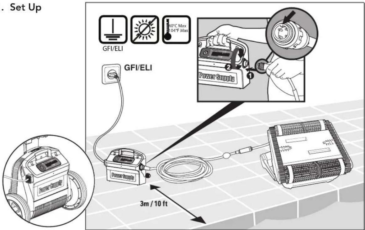
5.1. Set Up
text_image
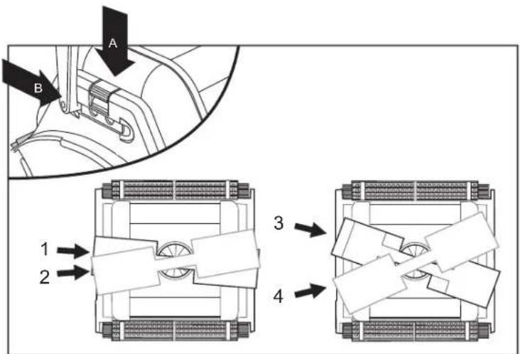
. Set Up GFI/ELI 10°C Max 104°F Max GFI/ELI Power Supply 3m / 10 ftChange diagonal handle position for water line sideway movement.
To adjust the handle angle:
A. Press the latch down and hold it in position.
B. Move the handle to the desired position and release the latch to hold the handle in place.
text_image
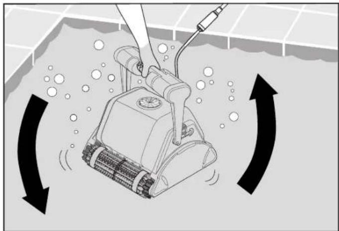
A B 1 2 3 45.2. Putting the Pool Cleaner into the pool
If Wonder brush/ Wonder rings are dry, soak them in water until soft.
Shake the robot from side to side or turn it upside down to release trapped air. Let it sink to the pool floor.
natural_image
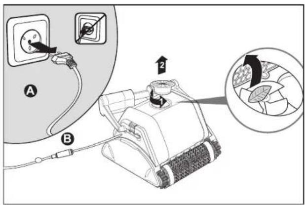
Illustration of a robotic vacuum cleaner inside a pool with directional arrows indicating flow or movement (no text or symbols)Turn the power supply ON
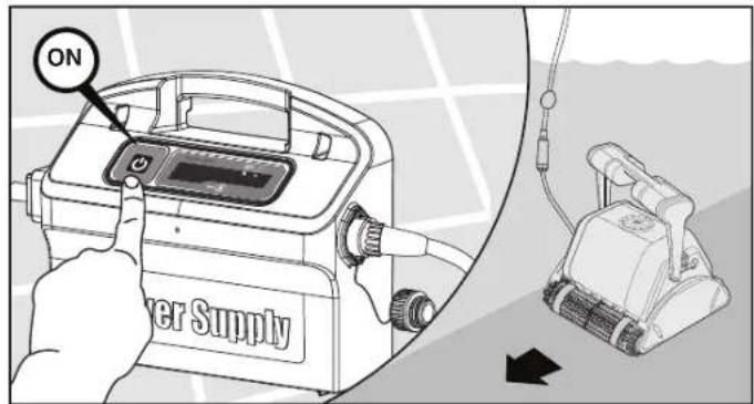
text_image
ON Power Supply5.3. Removing the Pool Cleaner from the pool
The robot will perform automatic shut-off at the end of the cleaning cycle.

Turn Off and unplug the power supply
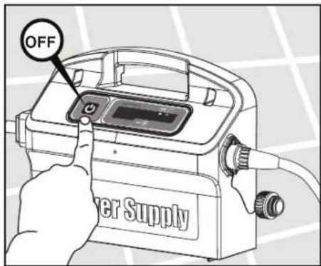
text_image
OFF Power Supply
text_image
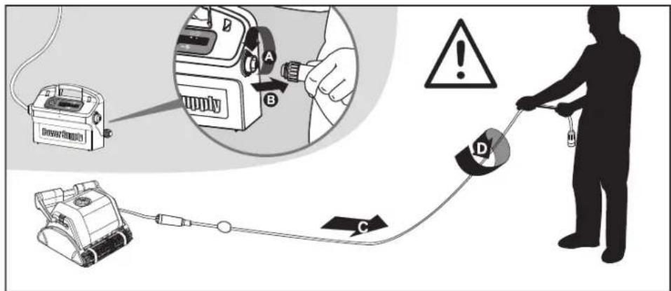
Diagram illustrating three steps of a robotic lawn curling device: manual tool, mechanical arm, and electrical switch.Using the floating cable, bring the Pool Cleaner to the pool's edge.

DO NOT PULL THE POOL CLEANER FROM THE POOL USING THE CABLE
5.4. Maintenance
Clean the filter bag with a hose. Periodically clean the brushes with a hose. It is recommended to periodically wash the filter bag in a washing machine. Use gentle cycle program.
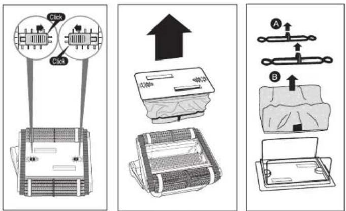
text_image
Click Click A B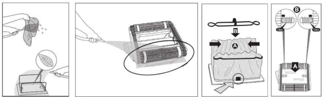
text_image
Diagram illustrating a food cleaning procedure with labeled steps A and B, showing steps from cleaning to handling or adjusting a food item.Cleaning the impeller

Unplug the power supply
If you notice debris trapped in the impeller open the impeller and remove the debris.
text_image
Diagram showing electrical socket installation with labeled components A and B, including a magnified inset of a device with internal wiring.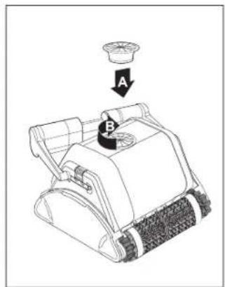
text_image
Diagram of a device with labeled parts A and B, showing a component being inserted into a bowl.Cable
To remove the kinks, stretch the cable out completely and let it sit for at least a day in the sun.
text_image
Safety warning illustration showing a person using a handheld device to clean a device with labeled components A, B, C, and D.5.5. Off-season storage
If the pool cleaner will not be in use for an extended period, perform the following storage steps:
• Make sure that no water is left in the pool cleaner
• Thoroughly clean the filter bag and insert in place
- Roll up the cable so that it has no kinks and place on the Caddy
- Store the pool cleaner in a protected area either on its Caddy or simply upsidedown
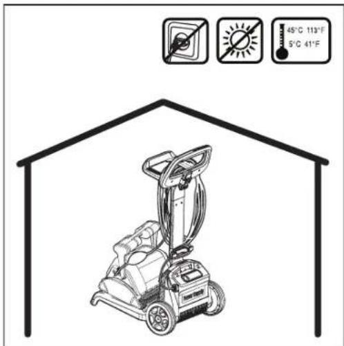
text_image
65°C 113°F 5°C 41°F6. POWER SUPPLY
Digital "Switch-Mode" Power Supply with full filter bag and delay indicator.
• Input - 100-250 AC Volts
- 50-60 Hertz
• 180 Watt
• Output - <30 VDC
IP 54
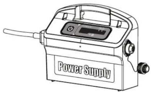
natural_image
Line drawing of a power supply device with control panel and handle (no text or symbols on the device itself)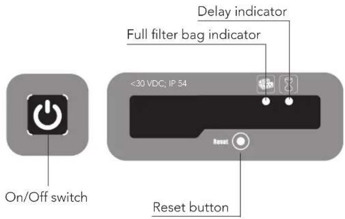
text_image
On/Off switch <30 VDC, IP 54 Delay indicator Full filter bag indicator Reset button
Full filter bag indicator and Reset button
The power supply is equipped with a filter bag status indicator.
The red LED indicates two filter conditions.
- When blinking - The filter is partially blocked.
- When lighted - The filter is blocked and must be emptied and cleaned.
If the LED does not turn off after the filter bag had been emptied and cleaned, press the RESET button while the robot is working.

Delay indicator
The power supply is equipped with a Delay indicator that indicates if the Delay option is activated (through the remote control unit).
7. REMOTE CONTROL UNIT
The Control Panel
The remote control unit (RCU) offers two operation modes – Automatic mode and manual direction control mode.
In automatic mode, the cleaning parameters can be changed.
In manual direction mode, the robot's motion can be controlled manually.
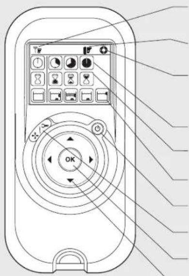
text_image
Diagram of a remote control device with labeled buttons and display screen, showing navigation arrows and function icons.Radio reception meter
When no black lines are showing, move closer to the power supply unit
Battery level meter
When flashing, change the batteries
Manual control indicator
When flashing, you are in manual direction control mode
Cleaning cycle icons
Delay timer icons
Cleaning mode icons
ON/OFF button
Manual/automatic select button
Set/OK button
Direction control arrows
| Manual Direction Control Mode | ||
| 1. Press the On/Off button once. The remote control will start in manual direction control mode.2. Use the direction control arrows (see right) to control the movement of the robot around the pool. | ||
| Exiting Manual Direction Control Mode and setting the Automatic Mode | ||
| Manual/AutomaticSelectbutton | 1. To exit the manual direction control mode, press the Manual/Automatic select button once only.2. The digital screen will light up and three rows of function icons will be displayed in default mode. | |
| Directioncontrolarrows | 1. To change the parameters press the up or down arrows.2. To select the parameter settings use the right or left arrows. When you reach the required function press the Set/OK button. | |
Press the Manual/Automatic select button and then choose the desired parameters according to the following table:
 Cleaning cycle indicatorThis determines the length of the cleaning cycle. Cleaning cycle indicatorThis determines the length of the cleaning cycle. |  Fast4-hour cycle Fast4-hour cycle |  Efficient6-hour cycle for everyday use.(Default setting) Efficient6-hour cycle for everyday use.(Default setting) |  Extra8-hour cycle Extra8-hour cycle | |
 Delay time indicatorThis determines when the pool cleaner starts to work. Delaying allows the dirt to settle to the bottom of the pool. Delay time indicatorThis determines when the pool cleaner starts to work. Delaying allows the dirt to settle to the bottom of the pool. |  Immediate start (Default setting) Immediate start (Default setting) |  One-hour delay One-hour delay |  Two-hour delay Two-hour delay | |
 Cleaning action indicatorAllowing you to choose from the following options. Cleaning action indicatorAllowing you to choose from the following options. |  StandardFloor and wall cleaning.(Default setting) StandardFloor and wall cleaning.(Default setting) |  Ultra-cleanStronger suction and slower movement.(floor and wall) Ultra-cleanStronger suction and slower movement.(floor and wall) |  Floor onlyCleans only the floor and the area where the floor and walls meet Floor onlyCleans only the floor and the area where the floor and walls meet | Walls onlyCleans walls and waterline only |
Note:
- After 2 minute if no button is pressed, the Remote Control Unit will shut-down and the Pool cleaner will continue to work in the previous settings.
- When the "Ultra-Clean" and "Walls Only" options finish their cycles, the Pool Cleaner will return to default settings.
FR
natural_image
Illustration of a robotic vacuum cleaner cleaning water surface with circular arrows indicating clockwise motion (no text or symbols)text_image
ON Power Supplytext_image
OFF Power Supply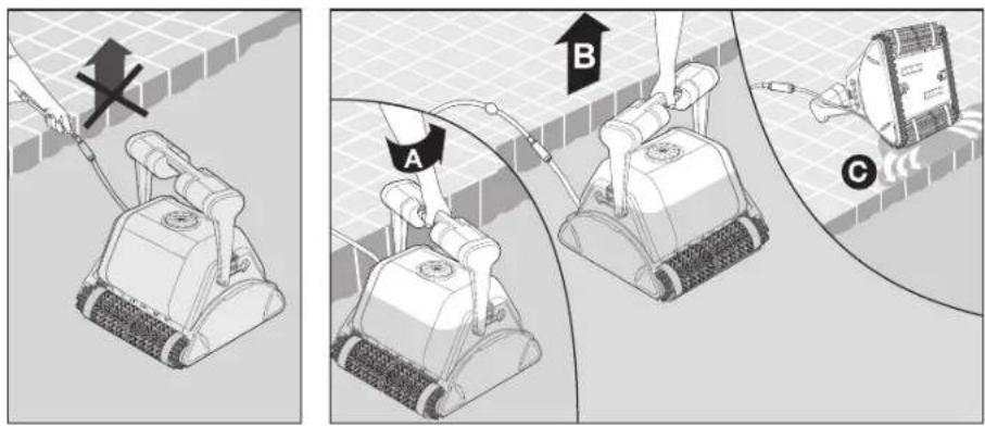
text_image
Diagram illustrating three steps of a robotic lawn curling device: manual press, mechanical arm joint, and sensor installation.text_image
Click Click A B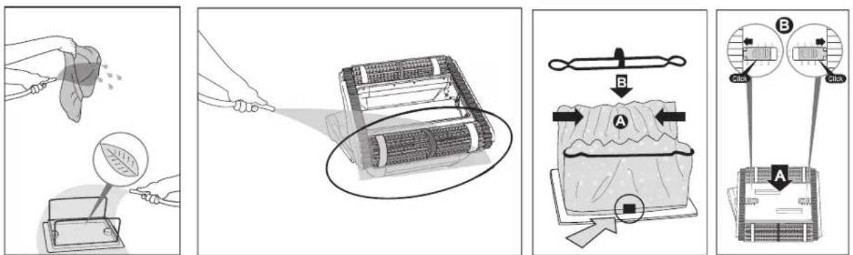
text_image
Diagram illustrating four steps of cleaning a battery, showing cleaning, packaging, rolling pin, and cleaning with labeled components A and B.text_image
Diagram illustrating electrical installation steps with labeled components A and B, showing connections to a device with numbered parts.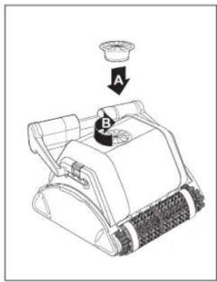
text_image
Diagram of a mechanical device with labeled parts A and B, showing a component being inserted into a bowl.Câble
text_image
Safety warning illustration showing a person using a power detector to clean a device, with labeled components A, B, C and warning symbol.text_image
On/Off switch <30 VDC, IP 54 Delay indicator Full filter bag indicator Reset button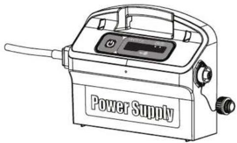
natural_image
Line drawing of a power supply device with control panel and buttons (no text or symbols on body)
natural_image
Illustration of a cleaning or cleaning robotic device with rotating arrows indicating flow or movement (no text or symbols)text_image
ON Power Supplytext_image
OFF Power Supply
text_image
Diagram illustrating three steps of a robotic lawn curling device: manual press, mechanical arm joint, and sensor installation.text_image
Diagram illustrating four steps of cleaning a leaf, showing material inspection, rolling device, fabric pressing, and cleaning with labeled components A and B.IT
text_image
Diagram illustrating a device installation procedure with labeled components and a magnified view showing internal components.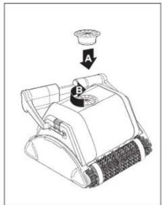
text_image
Diagram of a mechanical device with labeled parts A and B, showing a component being lifted by a bowl.Cavo
text_image
Safety warning illustration showing a person using a power meter to prevent electric shock, with labeled components and warning symbols.text_image
On/Off switch <30 VDC, IP 54 Delay indicator Full filter bag indicator Reset button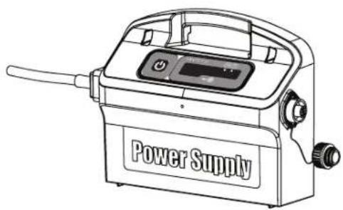
natural_image
Line drawing of a power supply device with handle and control panel (no text or symbols on body)
natural_image
Illustration of a cleaning or cleaning robotic device with directional arrows indicating flow or movement (no text or symbols)text_image
ON Power Supplytext_image
OFF Power Supply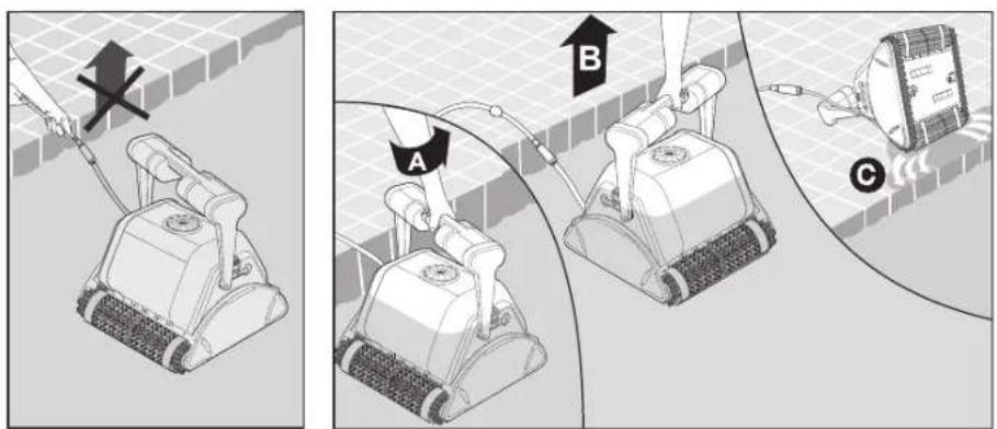
text_image
Diagram illustrating three steps of a lawn curling device: before, after, and after installation.text_image
Click Click A B
text_image
Diagram illustrating a food cleaning procedure with labeled steps A and B, showing steps from cleaning to packaging.text_image
Diagram illustrating a power switch installation process with labeled components A and B, showing wiring and component layout.
text_image
Diagram of a mechanical device with labeled parts A and B, showing a component being inserted into a bowl.Cable
text_image
Safety warning illustration showing a person using a portable device connected to a power strip, with labeled components A, B, C and warning symbol.natural_image
Line drawing of a power supply device with control panel and handle (no text or symbols on the device itself)
text_image
On/Off switch <30 VDC, IP 54 Reset button Delay indicator Full filter bag indicator
natural_image
Illustration of a cleaning or cleaning robotic device with rotating arrows indicating flow or movement (no text or symbols)text_image
ON Power Supplytext_image
OFF Power Supply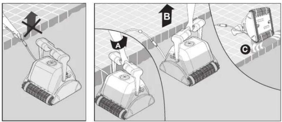
text_image
Diagram illustrating three steps of a robotic lawn curling device: before, after, and after installation.text_image
Diagram illustrating a food cleaning procedure with labeled steps A and B, showing steps from cleaning to handling and adjusting a food item.text_image
Diagram showing electrical socket installation with labeled components A and B, including a magnified inset of a device detail.
text_image
Diagram of a mechanical device with labeled parts A and B, showing a component being inserted into a bowl.Kabel
text_image
Safety warning illustration showing a person using a power detector to prevent a device with labeled components A, B, C and warning symbolnatural_image
Line drawing of a power supply device with control panel and buttons (no text or symbols on body)
text_image
On/Off switch <30 VDC, IP 54 Delay indicator Full filter bag indicator Reset button
natural_image
Illustration of a cleaning or cleaning robotic device with rotating arrows indicating flow or movement (no text or symbols)text_image
ON Power Supplytext_image
OFF Power Supply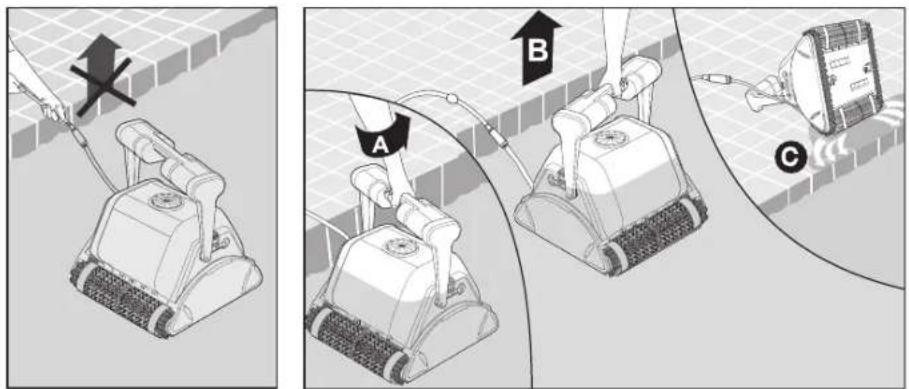
text_image
Diagram illustrating three steps of a robotic lawn curling device: manual tool, mechanical arm, and sensor device.text_image
Click Click A B
text_image
Diagram illustrating a food cleaning or packaging process with labeled steps A and B, showing steps from raw material to final product.De impeller reinigen

text_image
Diagram illustrating a power plug installation process with labeled components A and B, showing electrical socket, valve, and component layout.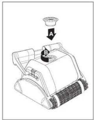
text_image
Diagram of a mechanical device with labeled parts A and B, showing a component being inserted into a bowl.Kabel
text_image
Safety warning illustration showing a person using a power meter connected to a device with labeled components A, B, and C.natural_image
Line drawing of a power supply device with control panel and handle (no text or symbols on the device itself)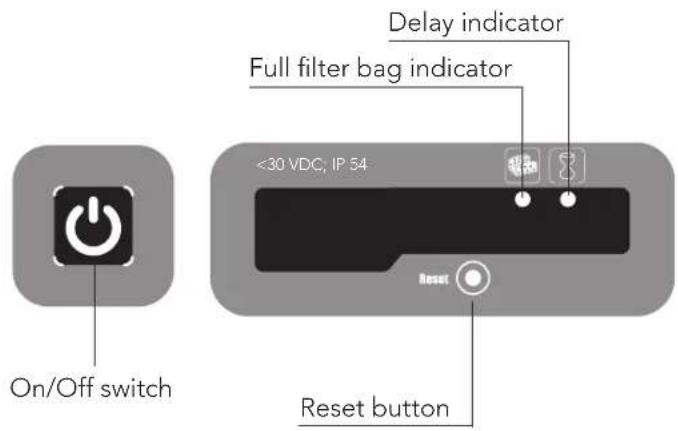
text_image
On/Off switch <30 VDC, IP 54 Delay indicator Full filter bag indicator Reset button
Volle filterzak indicatie en Reset knop
natural_image
Illustration of a cleaning or cleaning robotic device with directional arrows indicating flow or movement (no text or symbols)text_image
ON Power Supplytext_image
OFF Power Supply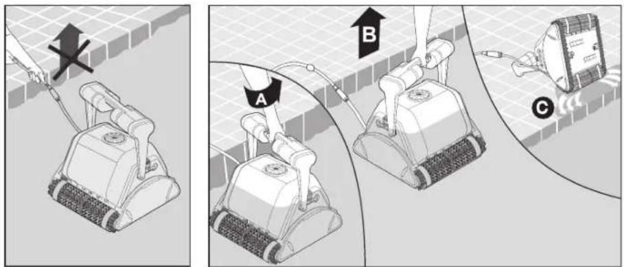
text_image
Diagram illustrating three steps of a robotic lawn curling device: manual tool, mechanical arm, and electrical switch.text_image
Click Click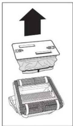
text_image
Diagram showing three types of household appliances: a refrigerator, a washing machine, and a microwave oven, with an upward arrow indicating the increase.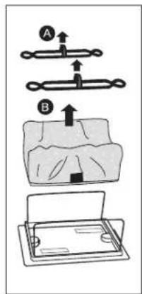
text_image
Diagram illustrating a dental procedure with labeled steps A and B showing movement of a tooth-like object.
natural_image
Illustration showing a leaf being injected from a container with a magnified view of the leaf inside (no text or symbols)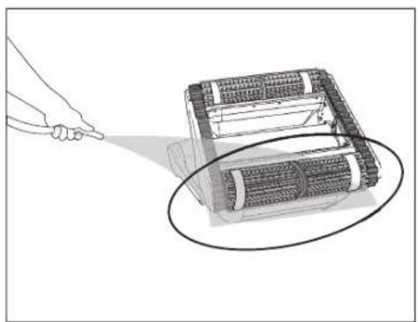
natural_image
Illustration of a robotic device with a hand pointing to it, showing internal components and motion lines (no text or symbols)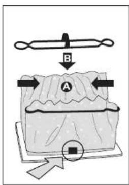
text_image
B A
flowchart
graph TD
    B["Component B"] --> C["CIBX"]
    B --> D["CIBX"]
    C --> E["Central Structure"]
    D --> E
    E --> F["Output"]
Limpeza do impulsor

text_image
Diagram illustrating a power plug installation process with labeled components and a magnified view of the device's internal structure.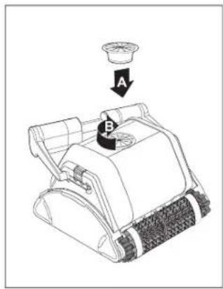
text_image
Diagram of a robotic device with labeled parts A and B, showing a component being inserted into a bowl.Cabo
text_image
Safety warning illustration showing a person using a device to clean electrical meters, with labeled components and warning symbols.5.5. Armazenamento fora de época
natural_image
Line drawing of a power supply device with control panel and hose (no text or symbols on body)
text_image
On/Off switch <30 VDC, IP 54 Delay indicator Full filter bag indicator Reset button
natural_image
Diagram of a cleaning or cleaning robotic device with directional arrows indicating flow or movement (no text or symbols present)text_image
ON Power Supplytext_image
OFF Power Supply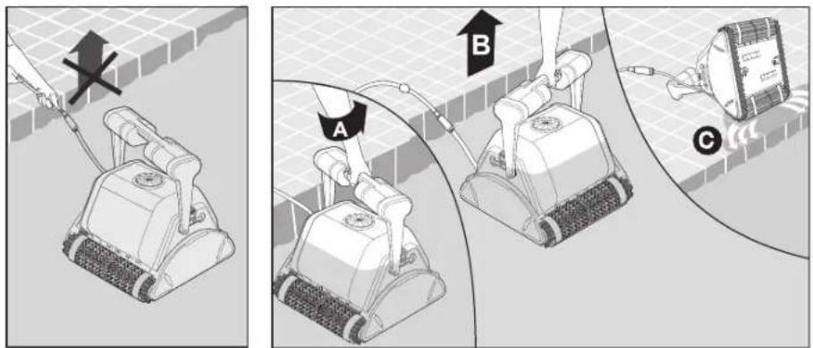
text_image
Diagram illustrating three steps of a robotic lawn curling device: manual tool, mechanical arm, and electrical switch.text_image
Click Click A B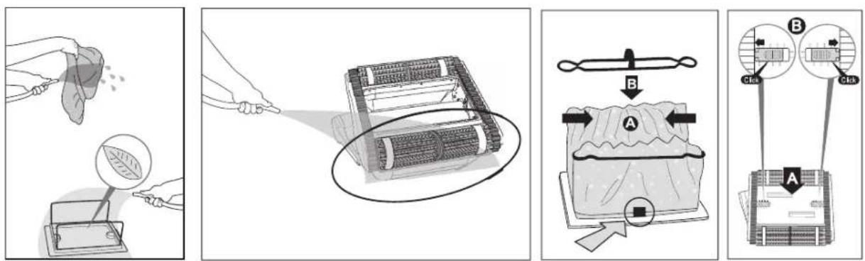
text_image
Diagram illustrating a cleaning or packaging process with labeled steps A and B, showing steps from cleaning to cleaning.text_image
Diagram illustrating a mechanical device with labeled parts A and B, showing electrical connections and a magnified inset of the component.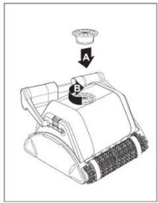
text_image
Diagram of a mechanical device with labeled parts A and B, showing a component being inserted into a bowl.Кабель
text_image
Safety warning illustration showing a person using a power pump to clean electrical equipment with labeled components A, B, and C.natural_image
Line drawing of a power supply device with control panel and buttons (no text or symbols on body)
text_image
On/Off switch <30 VDC, IP 54 Reset Reset button Full filter bag indicator Delay indicator
Dolphin PROX 2 Gyro Pool Cleaner
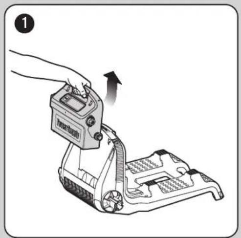
EN Caddy assembly
FR Caddy de montage
natural_image
Line drawing of a cleaning or cleaning tool with wheels and handle (no text or symbols)| 1 | DIN 7985 A2 M5X35 | x2 | |
| 2 | DIN 127B A2 M5 | x2 | |
| 3 | DIN 1587 A2 M5 | x2 | |
| 4 | WN 1412 A2 KA50X16 | x6 |
natural_image
Illustration of a hand operating a device with an arrow indicating motion (no text or symbols present)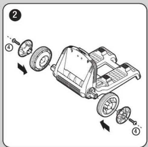
text_image
Diagram of a vehicle chassis with labeled parts and directional arrows indicating assembly or disassembly.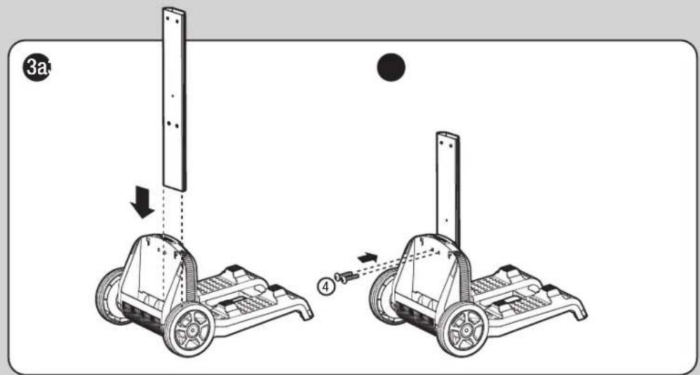
text_image
3a ④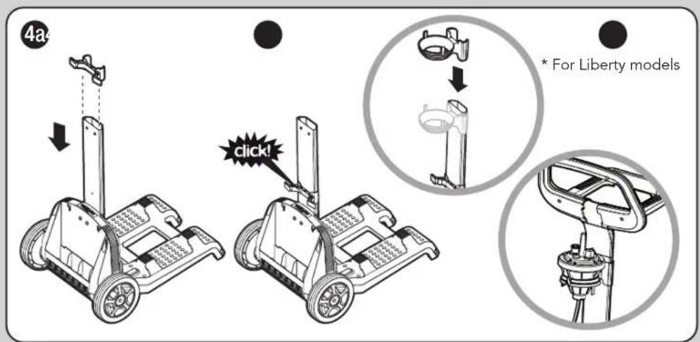
text_image
4a * For Liberty models click!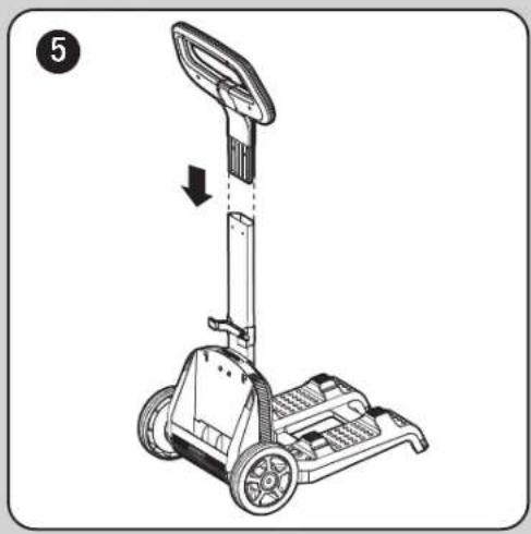
natural_image
Line drawing of a mobile phone with wheels and a vertical-mounted device, no text or symbols present
text_image
6 ⑥ ① ② ③ ④ ⑤ 8mm (5/16")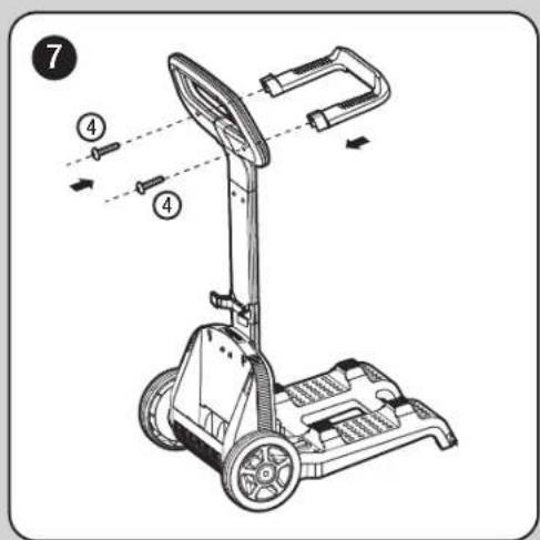
text_image
Technical diagram of a mobile phone with labeled parts and directional arrows indicating motion or assembly.
natural_image
Illustration of a hand using a handheld device to lift a cart, showing the mechanism (no text or symbols present)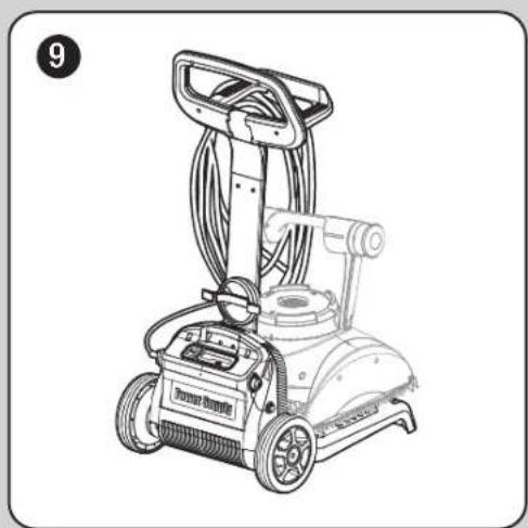
natural_image
Line drawing of a portable cleaning or cleaning machine with visible wheels and control panel (no text or symbols)
text_image
10 click!