Dolphin Premier - Pool MAYTRONICS - Free user manual and instructions
Find the device manual for free Dolphin Premier MAYTRONICS in PDF.

User questions about Dolphin Premier MAYTRONICS
0 question about this device. Answer the ones you know or ask your own.
Ask a new question about this device
Download the instructions for your Pool in PDF format for free! Find your manual Dolphin Premier - MAYTRONICS and take your electronic device back in hand. On this page are published all the documents necessary for the use of your device. Dolphin Premier by MAYTRONICS.
USER MANUAL Dolphin Premier MAYTRONICS
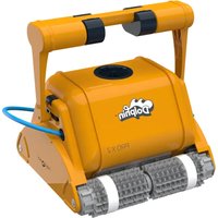
Dolphin Classic 5 / Top 5 Pool Cleaner
EN Operating Instructions p. 1-10
natural_image
Exterior view of a modern robotic device with dual circular heads and mesh base (no text or symbols visible)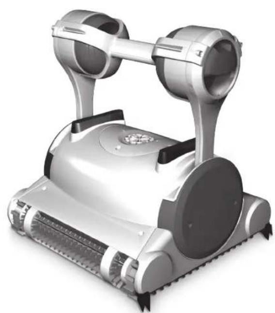
natural_image
3D rendering of a robotic vacuum cleaner with dual-mounted fans and mesh blades (no text or symbols visible)


EN
Robotic Pool Cleaner
Dolphin Classic 5 / Top 5
Operating Instructions
Contents
- INTRODUCTION 2
- SPECIFICATIONS 2
- WARNINGS AND CAUTIONS....2
3.1Warnings....2
3.2 Cautions....2
- POOL CLEANER PARTS....3
- USING THE POOL CLEANER....4
5.1 Setup....4
5.2 Putting the Pool Cleaner into the pool....5
5.3 Removing the Pool Cleaner from the pool....5
5.4 Maintenance....6
5.5 Off-season storage 7
- POWER SUPPLY - model Top 5 only 8
- REMOTE CONTROL UNIT - model Top 5 only....9
CADDY ASSEMBLY 71
Robotic Pool Cleaner Dolphin Classic 5 / Top 5
Operating Instructions
1. INTRODUCTION
Thank you for purchasing a Maytronics Robotic Pool Cleaner.
We are sure that your Maytronics Robotic Pool Cleaner will provide you with reliable, convenient and cost effective pool cleaning. Its reliable filtration in all pool conditions and all-surface climbing brush enhance maximum pool hygiene.
The Robotic Pool Cleaners by Maytronics deliver advanced cleaning technologies, long lasting performance and easy maintenance.
2. SPECIFICATIONS
Motor protection: IP 68
Minimum depth: 0.80m/2.6ft
Maximum depth: 5m/16.4ft
3. WARNINGS AND CAUTIONS
3.1 Warnings

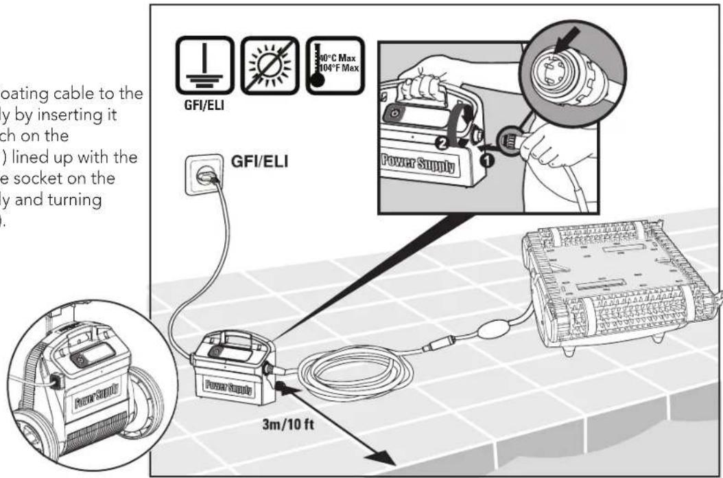
• Use the originally supplied power supply only
- Ensure the electrical outlet is protected by a ground fault interrupter (GFI) or an earth leakage interrupter (ELI)
- Keep the power supply out of standing water
- Position the power supply at least 3m/10ft away from the edge of the pool
- Do not enter the pool while the pool cleaner is working
• Unplug the power supply before servicing
3.2 Cautions
When not in use store the Pool Cleaner on the Caddy in a shaded area.
Use the Pool Cleaner in the following water conditions only:
| Chlorine Maximum | 4 ppm |
| pH 7.0 - 7.8 | |
| Temperature 6 – 34°C / 43-93°F | |
| NaCl Maximum 5000 ppm | |
4. POOL CLEANER PARTS
▶ Robotic Pool Cleaner Model Classic 5
natural_image
Line drawing of a robotic lawn mower with mesh base and attached arm (no text or symbols)Robotic Pool Cleaner Model Top 5
text_image
Remote control unitBrushes
text_image
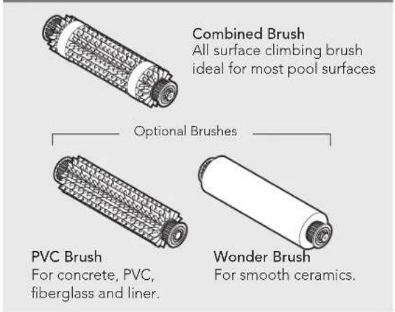
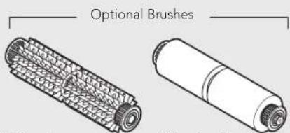
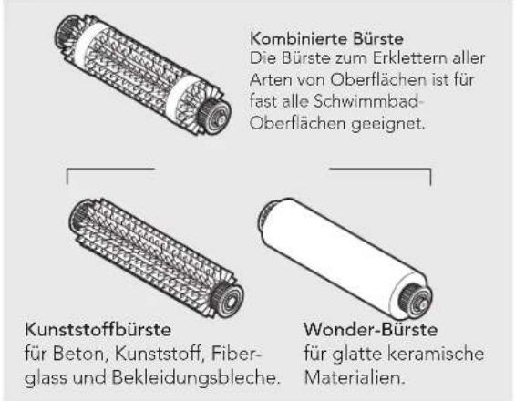
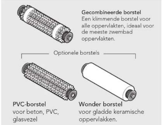
Combined Brush All surface climbing brush ideal for most pool surfaces Optional Brushes PVC Brush For concrete, PVC, fiberglass and liner. Wonder Brush For smooth ceramics.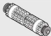
Combined Brush
All surface climbing brush ideal for most pool surfaces
text_image
Optional BrushesPVC Brush
For concrete, PVC, fiberglass and liner.
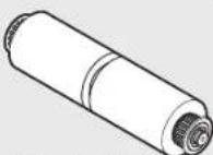
Wonder Brush
For smooth ceramics.
▶ Power supply unit
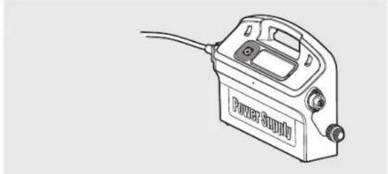
natural_image
Line drawing of a power supply device with attached cable (no text or symbols)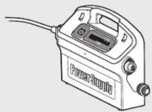
natural_image
Line drawing of a power supply device with cable and control buttons (no text or symbols)▶ Filtration options
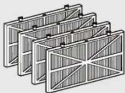
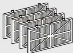
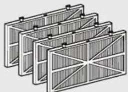
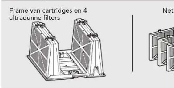
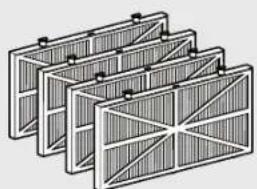
Frame Cartridges and 4 ultra-fine filters
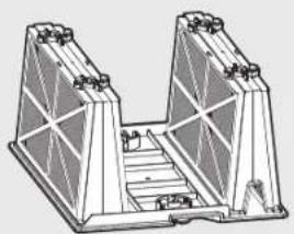
natural_image
Technical line drawing of a structural support structure with triangular supports and a central platform (no text or symbols)Net filters
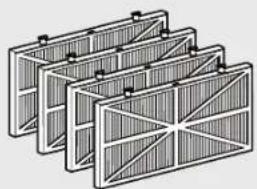
natural_image
Stacked rectangular panels with diagonal bracing, no text or symbols visibleBottom lid and filter Bag
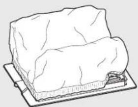
natural_image
Line drawing of a rectangular object placed on a flat base, resembling a cheese or cheese plate (no text or symbols)5. USING THE POOL CLEANER
5.1 Set Up
Initial float set up prior to first use - Classic 5 model only
- Place cable at the right side in front of the handle.
- Float position with various type of brushes:
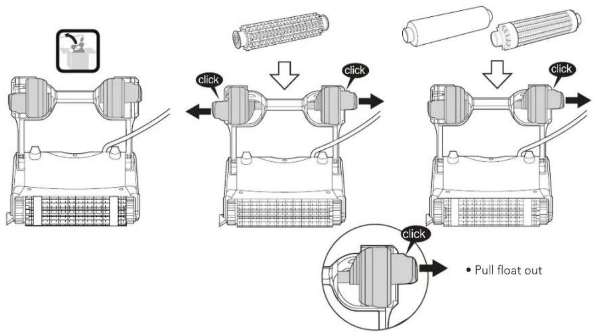
text_image
click click click click • Pull float outAttach the floating cable to the power supply by inserting it with the notch on the connector (1) lined up with the groove in the socket on the power supply and turning clockwise (2).
text_image
floating cable to the by inserting it ch on the ) lined up with the e socket on the y and turning GFI/ELI 30°C Max 104°F Max Power Supply GFI/ELI 3m/10 ft5.2 Putting the Pool Cleaner into the pool
If Wonder brush/ Wonder rings are dry, soak them in water until soft.
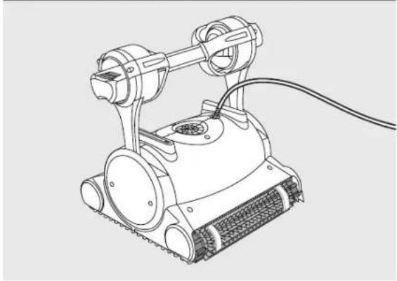
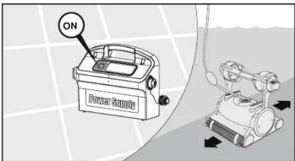
Shake the robot from side to side or turn it upside down to release trapped air. Let it sink to the pool floor.
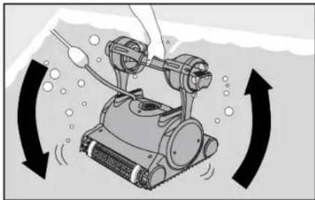
natural_image
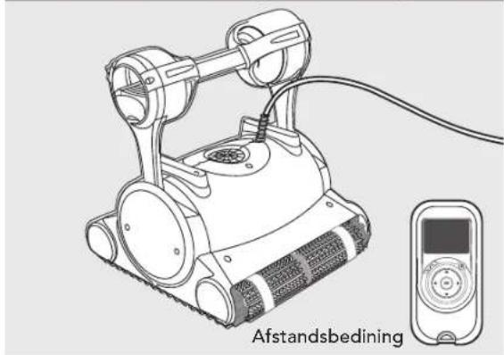
Illustration of a robotic device with rotating arrows indicating rotational motion (no text or symbols)Turn the power supply ON.
The Pool Cleaner will now operate until it has reached the end of the cleaning cycle.
text_image
ON Power Supply5.3 Removing the Pool Cleaner from the pool
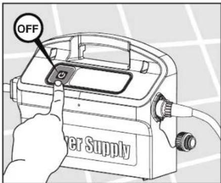
The robot will perform automatic shut-off at the end of the cleaning cycle.

Turn Off and unplug the power supply.
text_image
OFF Power Supply
natural_image
Illustration of a robotic arm with a hand operating it, showing mechanical components and a black arrow indicating direction (no text or symbols present)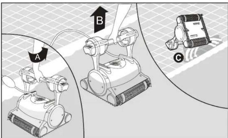
text_image
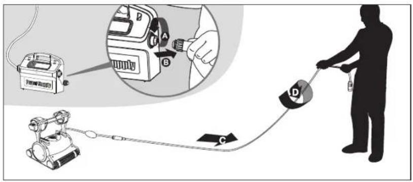
A B CUsing the floating cable, bring the Pool Cleaner to the pool's edge. Using the handle remove the Pool Cleaner from the pool.

DO NOT PULL THE POOL CLEANER FROM THE POOL USING THE CABLE.
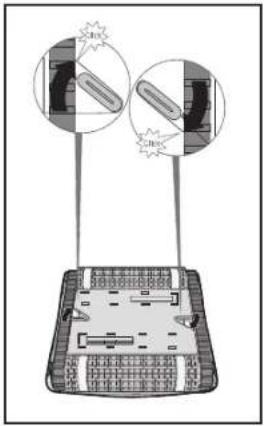
5.4 Maintenance
Cartridge
It is recommended to wash the cartridge after every cycle.
Filtration Options
• Ultra-fine filters for day-to-day use.
• Net filters for dirty pools with large debris such as leaves etc., useful for beginning of season.
natural_image
Diagram of a tank with attached sensors and a close-up view showing internal components (no text or symbols)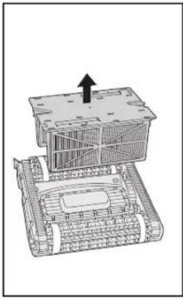
natural_image
Technical line drawing of a mechanical assembly with no visible text or symbols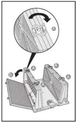
text_image
Technical diagram showing a mechanical assembly with labeled components A and B, including a magnified view of a component with rotation arrow.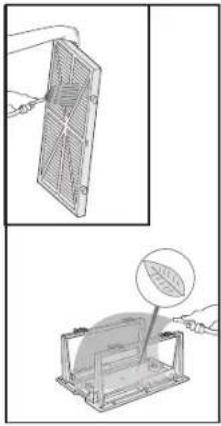
natural_image
Illustration of a battery pack being held by a hand, with a magnified view showing the internal structure (no text or symbols)Filter bag
Clean the filter bag with a hose. Periodically clean the brushes with a hose. It is recommended to periodically wash the filter bag in a washing machine. Use gentle cycle program.
text_image
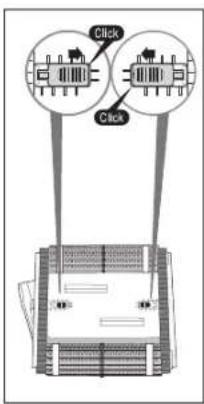
Click Click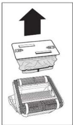
text_image
Diagram showing a printer with an upward arrow and a folded paper, likely illustrating a process or installation.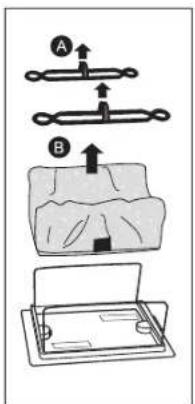
text_image
Diagram illustrating a mechanical assembly with labeled parts A and B, showing step-by-step assembly steps.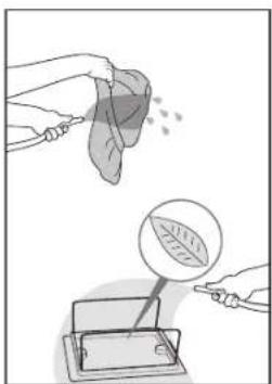
natural_image
Illustration showing a leaf being injected from a container with a magnified view of the leaf inside (no text or symbols)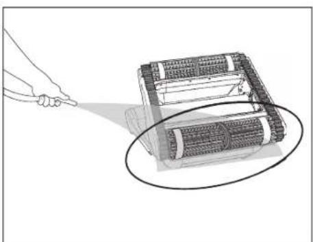
natural_image
Illustration of a hand using a tool to zoom onto a mechanical device component (no text or symbols visible)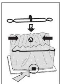
text_image
B A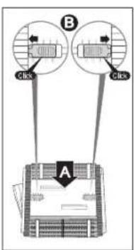
flowchart
graph TD
    B["Component B"] -->|Click| C["Device"]
    B -->|Click| C
    C --> D["Arrow pointing inward"]
    style B fill:#f9f,stroke:#333
    style A fill:#ccf,stroke:#333
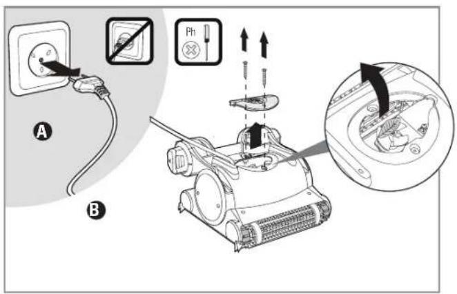
Cleaning the impeller

Unplug the power supply.
If you notice debris trapped in the impeller open the impeller and remove the debris.
text_image
Diagram illustrating electrical switch installation and component disassembly, showing power outlet, switch, and motor assembly with labeled parts A and B.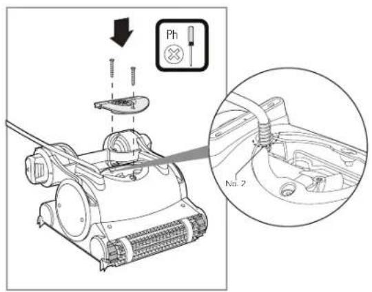
text_image
Ph No. 2Cable
To remove the kinks, stretch the cable out completely and let it sit for at least a day in the sun.
text_image
Diagram illustrating a person using a power supply device connected to a robotic device, with labeled parts A, B, C, D.5.5 Off-season storage
If the pool cleaner will not be in use for an extended period, perform the following storage steps:
• Make sure that no water is left in the pool cleaner.
• Thoroughly clean the filter bag and insert in place.
- Roll up the cable so that it has no kinks and place on the Caddy.
- Store the pool cleaner upright on the Caddy in a protected area out of direct sun/rain/frost at a temperature of between 5^ - 45^ / 41^ - 113^ .
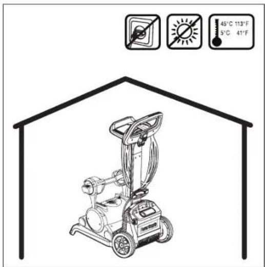
text_image
45°C 113°F 5°C 41°F6. POWER SUPPLY - MODEL TOP 5 ONLY
Digital "Switch-Mode" Power Supply with full filter bag and delay indicator.
• Input - 100-250 AC Volts
- 50-60 Hertz
• 180 Watt
• Output - <30 VDC
IP 54

text_image
On/Off switch <30 VDC; IP 54 Reset button Delay indicator Full filter bag indicator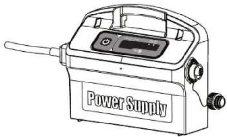
natural_image
Line drawing of a power supply device with control panel and buttons (no text or symbols on body)
Full filter bag indicator and Reset button
The power supply is equipped with a filter bag status indicator.
The red LED indicates two filter conditions.
- When blinking - The filter is partially blocked.
- When lighted - The filter is blocked and must be emptied and cleaned.
If the LED does not turn off after the filter bag had been emptied and cleaned, press the RESET button while the robot is working.

Delay indicator
The power supply is equipped with a Delay indicator that indicates if the Delay option is activated (through the remote control unit).
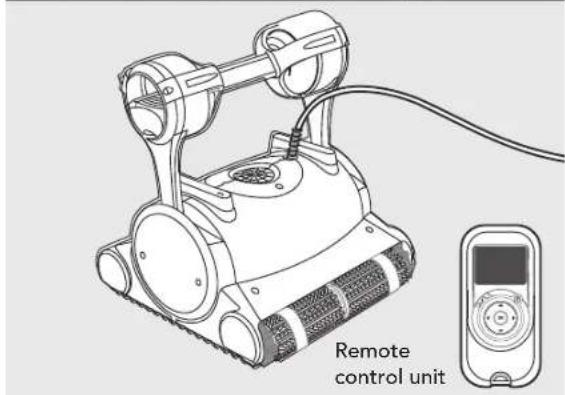
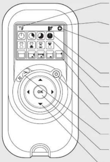
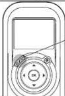
7. REMOTE CONTROL UNIT - MODEL TOP 5 ONLY
The Control Panel
The remote control unit offers two operation modes – Automatic mode and manual direction control mode.
In automatic mode, the cleaning parameters can be changed.
In manual direction mode, the robot's motion can be controlled manually.
text_image
Diagram of a remote control device with labeled buttons and function icons, showing navigation and operation controls.Radio reception meter
When no black lines are showing, move closer to the power supply unit
Battery level meter
When flashing, change the batteries
Manual control indicator
When flashing, you are in manual direction control mode
Cleaning cycle icons
Delay timer icons
Cleaning mode icons
ON/OFF button
Manual/automatic select button
Set/OK button
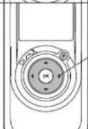
Direction control arrows
Manual Direction Control Mode
| 1. Press the On/Off button once. The remote control will start in manual direction control mode.2. Use the direction control arrows (see right) to control the movement of the robot around the pool. |
Exiting Manual Direction Control Mode and setting the Automatic Mode
 | Manual/Automatic Select button | 1. To exit the manual direction control mode, press the Manual/Automatic select button once only.2. The digital screen will light up and three rows of function icons will be displayed in default mode. | 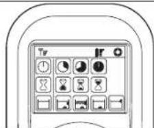 | |
 | Direction control arrows | 1. To change the parameters press the up or down arrows.2. To select the parameter settings use the right or left arrows. When you reach the required function press the Set/OK button. | 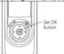 |
Press the Manual/Automatic select button and then choose the desired parameters according to the following table:
 Cleaning cycle indicatorThis determines the length of the cleaning cycle. Cleaning cycle indicatorThis determines the length of the cleaning cycle. |  Fast2-hour cycle Fast2-hour cycle |  Efficient3-hour cycle for everyday use.(Default setting) Efficient3-hour cycle for everyday use.(Default setting) |  Extra4-hour cycle Extra4-hour cycle | |
 Delay time indicatorThis determines when the pool cleaner starts to work. Delaying allows the dirt to settle to the bottom of the pool. Delay time indicatorThis determines when the pool cleaner starts to work. Delaying allows the dirt to settle to the bottom of the pool. |  Immediate start (Default setting) Immediate start (Default setting) |  One-hour delay One-hour delay |  Two-hour delay Two-hour delay | |
 Cleaning action indicatorAllowing you to choose from the following options. Cleaning action indicatorAllowing you to choose from the following options. |  StandardFloor and wall cleaning.(Default setting) StandardFloor and wall cleaning.(Default setting) |  Ultra-cleanStronger suction and slower movement.(floor and wall) Ultra-cleanStronger suction and slower movement.(floor and wall) |  Floor onlyCleans only the floor and the area where the floor and walls meet Floor onlyCleans only the floor and the area where the floor and walls meet | Walls onlyCleans walls and waterline only |
Note:
- After 2 minute if no button is pressed, the Remote Control Unit will shut-down and the Pool cleaner will continue to work in the previous settings.
- When the "Ultra-Clean" and "Walls Only" options finish their cycles, the Pool Cleaner will return to default settings.
FR
natural_image
Line drawing of a mechanical robotic device with mesh base and articulated arms (no text or symbols)natural_image
Line drawing of a robotic device with attached electronic device (no text or symbols on the device itself)natural_image
Line drawing of a power supply device with labeled buttons and cable (no text or symbols beyond branding)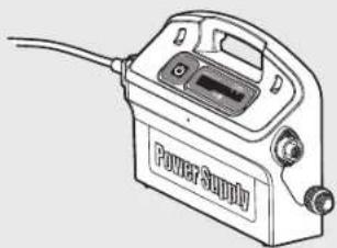
natural_image
Line drawing of a power supply device with visible ports and wiring (no text or symbols)natural_image
Technical line drawing of a structural support frame with two vertical supports and a central platform (no text or symbols)Filtre filet
natural_image
Stacked rectangular panels with diagonal bracing, no text or symbols visiblenatural_image
Line drawing of a rectangular object placed on a base, resembling a cheese or cheese plate (no text or symbols)5. UTILISATION DU NETTOYEUR DE PISCINE
5.1 Montage
natural_image
Illustration of a robotic device with rotating arrows indicating motion (no text or symbols)text_image
ON Power Supplytext_image
OFF Power Supply
text_image
Diagram illustrating robot arm joint positioning and movement, labeled A, B, and C with directional arrows and a device.natural_image
Diagram of a tank with two circular insets showing internal components, no text or symbols present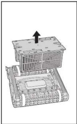
natural_image
Technical line drawing of a mechanical assembly with no visible text or symbols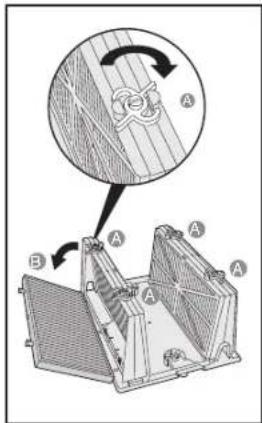
text_image
Technical diagram showing a mechanical assembly with labeled components A and B, including a magnified view of a wire loop detail.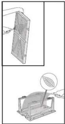
natural_image
Two-step diagram showing a panel being held and a leaf being inserted into a container (no text or symbols)Sac filtre
text_image
Click Click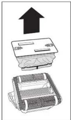
text_image
Diagram showing a device with an upward arrow and a compressed grid, likely illustrating a process or manufacturing process.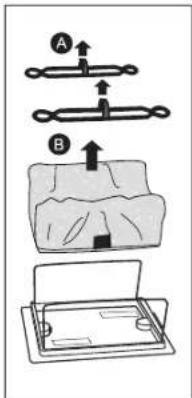
text_image
Diagram illustrating a mechanical assembly process with labeled parts A and B, showing step-by-step assembly steps.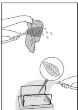
natural_image
Illustration showing a hand holding a leaf above a device with a magnified view of the leaf inside (no text or symbols)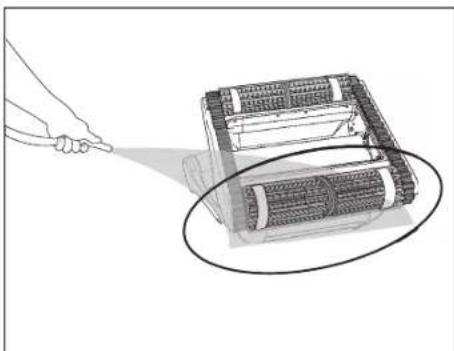
natural_image
Illustration of a hand using a flashlight to zoom onto a device component, with no visible text or symbols.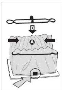
text_image
B A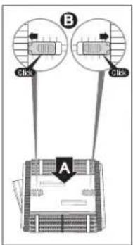
flowchart
graph TD
    B["Step B"] -->|Click| A["Rectangular Block Structure"]
    B -->|Click| A
text_image
Diagram illustrating electrical connection and component assembly with labeled parts A and B, including a plug, switch, and motor.
text_image
Technical diagram showing a mechanical assembly with labeled components and a magnified detail view of a component labeled No.2.Câble
text_image
Diagram illustrating a person using a handheld device to interact with a robot, labeled with components A, B, C, and D.natural_image
Line drawing of a power supply device with control panel and buttons (no text or symbols on body)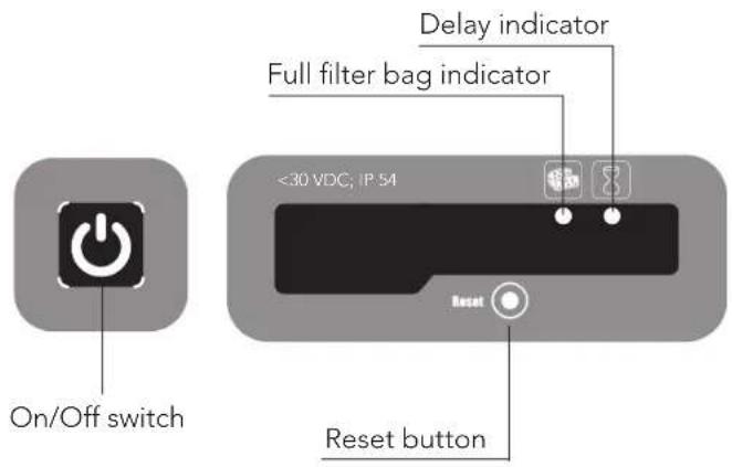
text_image
On/Off switch Delay indicator Full filter bag indicator <30 VDC; IP 54 Reset button
natural_image
Line drawing of a robotic device with articulated arms and mesh base (no text or symbols)natural_image
Line drawing of a tracked robotic device with attached control panel and remote control unit (no text or symbols on the robot itself)Spazzola "Wonder Brush"
natural_image
Line drawing of a power supply device with labeled components and wiring (no text or symbols beyond branding)
natural_image
Line drawing of a power supply device with visible ports and wiring (no text or symbols)natural_image
Technical line drawing of a mechanical structure with two triangular supports and internal channels (no text or symbols)Filtri a rete
natural_image
Illustration of multiple rectangular panels with internal grating patterns, no text or symbols presentnatural_image
Line drawing of a rectangular object placed on a baseplate with a ruler for scale (no text or symbols)5. UTILIZZAZIONE DEL PULITORE
5.1 Installazione
natural_image
Illustration of a robotic vacuum cleaner with rotating arrows indicating airflow or vibration (no text or symbols)text_image
ON Power Supplytext_image
OFF Power Supply
natural_image
Illustration of a robotic arm with a hand operating it, showing mechanical components and a black arrow indicating direction (no text or symbols present)
text_image
A B Ctext_image
Click Click
natural_image
Illustration of a device with an upward arrow and a grid-patterned base, no text or symbols present.
text_image
Diagram illustrating a mechanical or electrical setup with labeled components A and B, showing directional arrows and a component.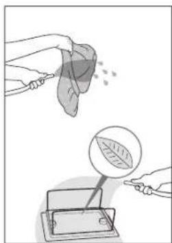
natural_image
Illustration showing a hand holding a leaf being sprayed, with a magnified view of a leaf inside a device (no text or symbols)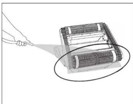
natural_image
Illustration of a hand using a flashlight to zoom the objective lens onto a mechanical device (no text or symbols visible)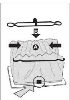
text_image
B A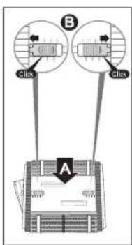
text_image
B Click Atext_image
Diagram illustrating electrical switch installation and component disassembly, with labeled parts A and B and a magnified inset showing internal components.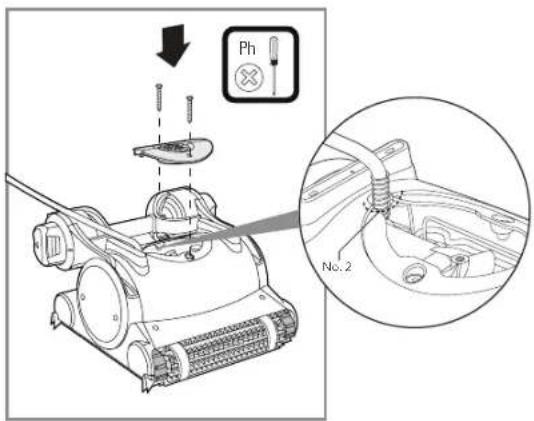
text_image
Technical diagram showing a mechanical device with a disassembled component and a close-up of its internal structure labeled No.2.Cavo
text_image
Diagram illustrating a person using a mobile phone to interact with a robot, showing labeled components A, B, and C.text_image
On/Off switch Delay indicator Full filter bag indicator <30 VDC; IP 54 Reset button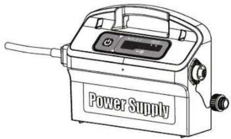
natural_image
Line drawing of a power supply device with control panel and buttons (no text or symbols on body)
text_image
Diagram of a remote control device with labeled buttons and function icons, showing navigation and operation controls.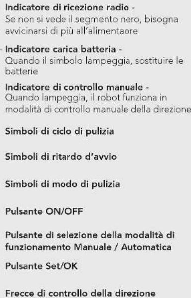
natural_image
Line drawing of a robotic device with mesh base and articulated arm (no text or symbols)natural_image
Line drawing of a power supply device with labeled ports and cable (no text or symbols beyond label)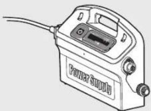
natural_image
Line drawing of a power supply device with cable and control panel (no text or symbols)natural_image
Technical line drawing of a mechanical or structural component with two symmetrical supports and internal channels (no text or symbols)Filtro de red
natural_image
Illustration of three identical rectangular panels with internal grid patterns, no text or symbols present.natural_image
Line drawing of a rectangular block on a base, resembling a cheese or cheese plate (no text or symbols)natural_image
Illustration of a robotic device with rotating arrows indicating rotational motion (no text or symbols)text_image
ON Power Supplytext_image
OFF Power Supply
natural_image
Illustration of a robotic arm with a hand operating it, showing mechanical components and a black arrow indicating direction (no text or symbols present)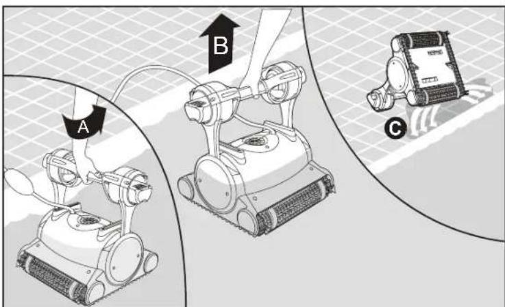
text_image
A B Ctext_image
Diagram showing a tank connected to two sensors with labeled ports and connection points, including magnified insets.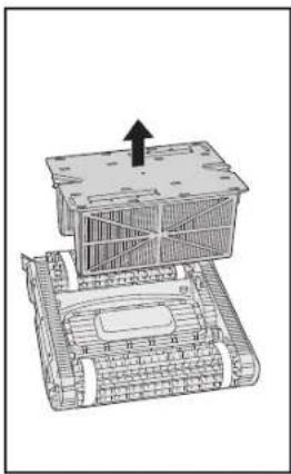
natural_image
Technical line drawing of a mechanical assembly with a central component and an upward arrow (no text or symbols)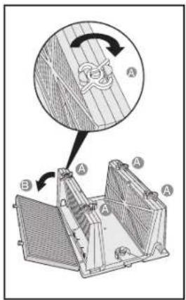
text_image
Technical diagram showing a mechanical assembly with labeled components A and B, including a magnified view of a wire meshing setup.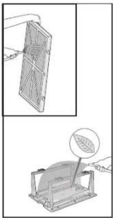
natural_image
Illustration of a device with a grid panel and a leaf inside, showing a close-up view (no text or symbols)Bolsa del filtro
text_image
Click Click
text_image
Diagram showing a device with an upward arrow and a compressed grid, likely illustrating a process or installation concept.
text_image
Diagram illustrating a mechanical assembly with labeled parts A and B, showing directional movement and component placement.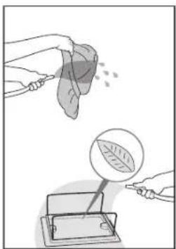
natural_image
Illustration showing a leaf being probed and inverted, with a magnified view of the leaf inside a device (no text or symbols)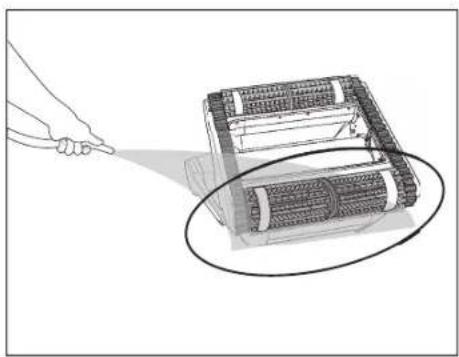
natural_image
Illustration of a hand pointing at a device with a magnified view showing internal components (no text or symbols)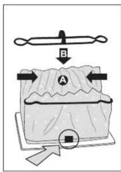
text_image
B A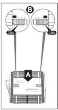
text_image
B Click Click Atext_image
Diagram illustrating electrical switch installation and component disassembly, with labeled parts A and B and a magnified view of the device's internal structure.
text_image
Technical diagram showing a mechanical device with a disassembly step and a close-up of a component labeled No.2, including a plunger and screwdriver.Cable
text_image
Diagram illustrating a person using a device to interact with a robot, labeled with components A, B, C, and D.natural_image
Line drawing of a power supply device with control panel and buttons (no text or symbols on body)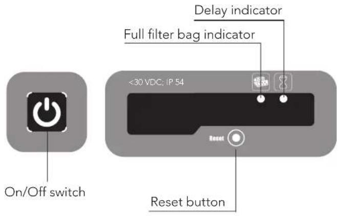
text_image
On/Off switch <30 VDC; IP 54 Reset button Delay indicator Full filter bag indicator
text_image
Diagram of a remote control device with labeled buttons and function keys, showing navigation and operation icons.Medidor de Radio-recepción -
natural_image
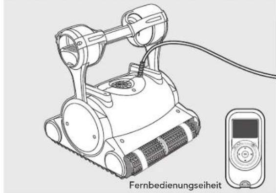
Line drawing of a robotic device with mesh base and articulated arm (no text or symbols)▶ Roboter-Poolreiniger Modell Top 5
natural_image
Illustration of a robotic device with a digital display and a separate control unit, labeled 'Fernbedienungseiheit' (no technical symbols or text on the device itself)Bürsten
natural_image
Line drawing of a power supply device with attached cable (no text or symbols on the device itself)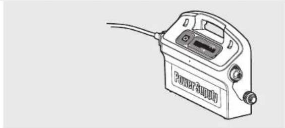
natural_image
Line drawing of a power supply device with cable and connector (no text or symbols)natural_image
Technical line drawing of a mechanical assembly with two triangular supports and a central platform (no text or symbols)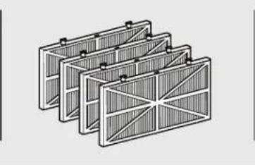
natural_image
Illustration of a multi-layered solar panel structure with no text or symbols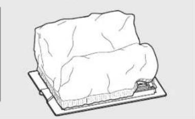
natural_image
Line drawing of a rectangular block on a flat base, resembling a cheese or cheese plate (no text or symbols)5. VERWENDUNG DES POOLREINIGERS
5.1 Einstellung
text_image
GFI/ELI 30°C Max 104°F Max GFI/ELI Power Supply 3m/10 ftnatural_image
Illustration of a robotic lawn mower with directional arrows indicating motion (no text or symbols)text_image
ON Power Supplytext_image
OFF Power Supply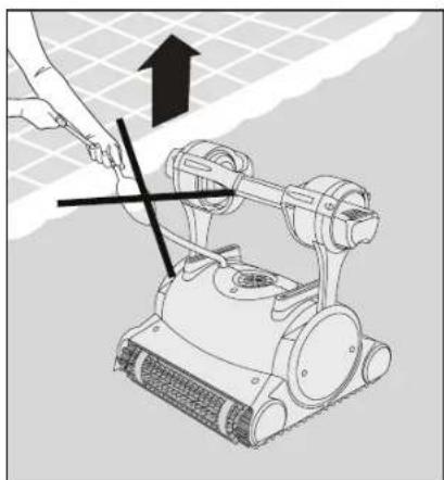
natural_image
Illustration of a robotic arm with a hand operating it, showing mechanical components and a black arrow indicating force direction (no text or symbols present)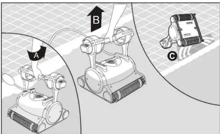
text_image
A B Cnatural_image
Diagram of a tank with attached sensors and wiring, showing internal components and connections (no text or symbols)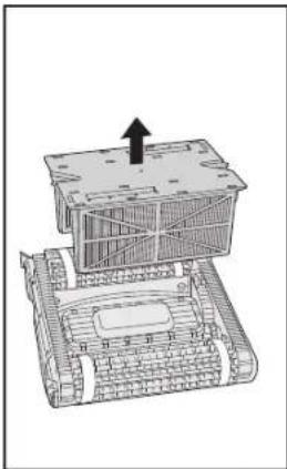
natural_image
Technical line drawing of a mechanical assembly with an upward arrow indicating force or movement (no text or symbols present)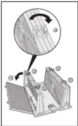
text_image
Technical diagram showing a mechanical assembly with labeled components A and B, including a circular inset view of a wire mesh structure.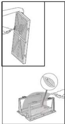
natural_image
Two technical diagrams showing a grid device being handled and a mechanical component with a leaf inside (no text or symbols)Filterbeutel
text_image
Click Click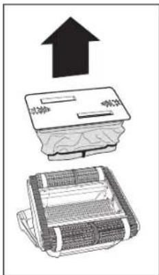
text_image
Diagram showing a device with an upward arrow and a compressed grid, likely illustrating a process or installation concept.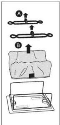
text_image
Diagram illustrating a mechanical assembly or folding process with labeled parts A and B, showing step-by-step assembly steps.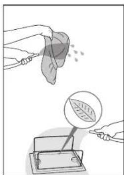
natural_image
Illustration showing a hand pouring leaf into a container with a magnified view of the leaf inside (no text or symbols)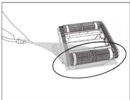
natural_image
Illustration of a hand using a flashlight to zoom onto a mechanical device (no text or symbols visible)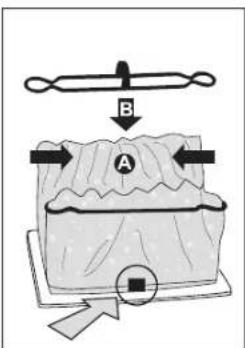
text_image
B A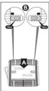
text_image
B Cilia Cilia Atext_image
Diagram illustrating electrical switch installation and component disassembly, showing power outlet, switch, and motor assembly with labeled parts A and B.
text_image
Technical diagram showing a mechanical device with a disassembly process and a magnified detail of the component labeled No. 2.Kabel
text_image
Diagram illustrating a robotic device connected to a device labeled A, B, C, D, with an inset showing a close-up of the device's cable and hand.natural_image
Line drawing of a power supply device with control panel and buttons (no text or symbols on body)
text_image
On/Off switch <30 VDC; IP 54 Reset button Delay indicator Full filter bag indicator
natural_image
Line drawing of a robotic device with articulated arms and mesh base (no text or symbols)▶ Robot Zwembadreiniger Model Top 5
natural_image
Line drawing of a robotic device with attached digital display and control panel (no text or symbols on the device itself)▶ Borstels
natural_image
Line drawing of a power supply device with attached cable (no text or symbols)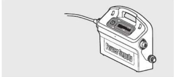
natural_image
Line drawing of a power supply device with labeled ports and cable (no text or symbols beyond branding)▶ Filtreer opties
text_image
Frame van cartridges en 4 ultradunne filters Net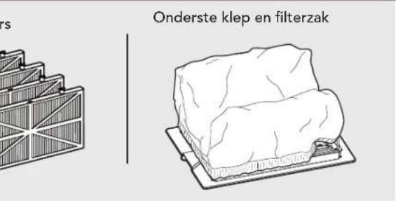
text_image
Onderste klep en filterzak5. DE zWEMBADREINIGER GEBRUIKEN
5.1 Instellen
natural_image
Illustration of a robotic device with rotating arrows indicating rotational motion (no text or symbols)text_image
ON Power Supplytext_image
OFF Power Supply
natural_image
Illustration of a robotic lawn mower with a hand operating it, showing mechanical components and a black cross symbol (no text or labels)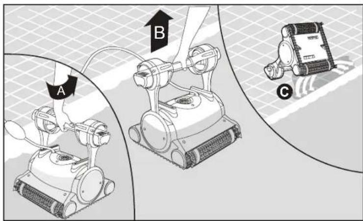
text_image
A B Ctext_image
Click Click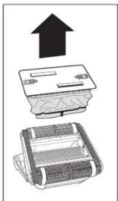
text_image
Diagram showing three components of a printer with an upward arrow, indicating a process or operation.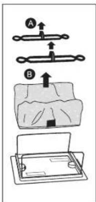
text_image
Diagram illustrating a mechanical or electrical assembly with labeled components A and B, showing directional arrows and layered structures.
natural_image
Illustration showing a leaf being poured into a container with a magnified view of the leaf inside (no text or symbols)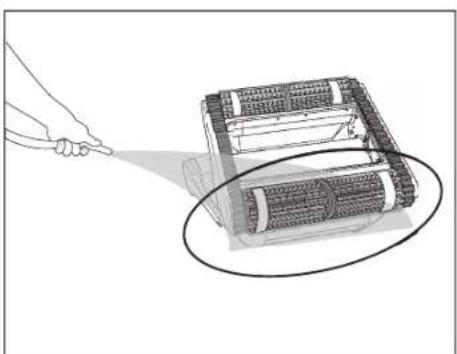
natural_image
Illustration of a robotic device with a hand pointing to it, showing internal components and a magnified view (no text or symbols)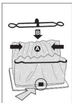
text_image
B A
text_image
B Click Click ADe impeller reinigen

text_image
Diagram illustrating electrical connection and component assembly with labeled parts A and B, including a plug, switch, and motor.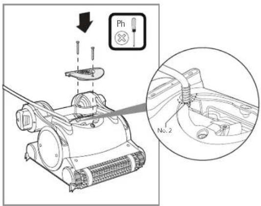
text_image
Technical diagram showing a mechanical assembly with labeled components and a magnified detail view of a component labeled No.2.Kabel
text_image
Diagram illustrating a person using a handheld device to interact with a robot, labeled with components A, B, C, and D.text_image
On/Off switch <30 VDC; IP 54 Delay indicator Full filter bag indicator Reset button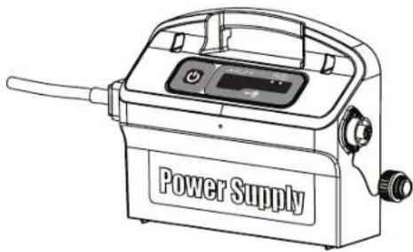
natural_image
Line drawing of a power supply device with control panel and buttons (no text or symbols on body)
Volle filterzak indicatie en Reset knop
natural_image
Line drawing of a mechanical robotic device with mesh base and articulated arms (no text or symbols)natural_image
Line drawing of a tracked robot with attached control panel (no text or symbols on the robot itself)natural_image
Line drawing of a power supply device with labeled components and wiring (no readable text or symbols beyond label)
natural_image
Line drawing of a power supply device with cable and ports (no text or symbols)▶ Opções filtragem
natural_image
Technical line drawing of a structural support frame with supports and internal components (no text or symbols)Filtro de rede
natural_image
Illustration of stacked rectangular panels with diagonal dividers (no text or symbols)natural_image
Line drawing of a rectangular object resting on a base, resembling a cheese or cheese block (no text or symbols)5. UTILIZAR O ASPIRADOR DE PISCINA
5.1 Instalação
natural_image
Illustration of a robotic device with rotating arrows indicating rotational motion (no text or symbols)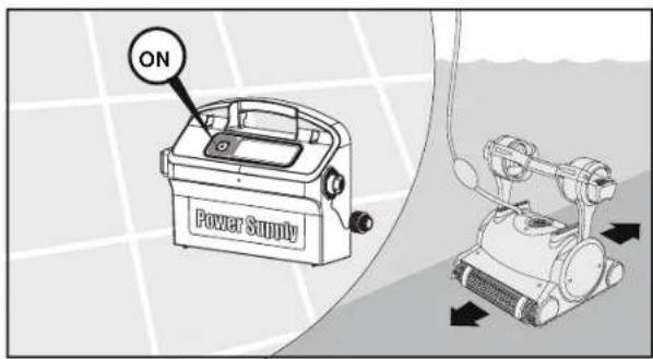
text_image
ON Power Supplytext_image
OFF Power Supply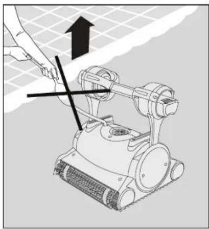
natural_image
Illustration of a robotic arm with a hand operating it, showing mechanical components and a black cross symbol (no text or labels)
text_image
A B Ctext_image
Click Click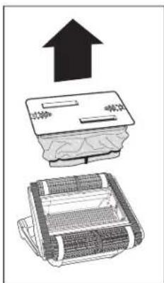
natural_image
Illustration of a device with an upward arrow and a textured base, no text or symbols present.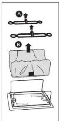
text_image
Diagram illustrating a mechanical or electrical setup with labeled components A and B, showing directional arrows and a component.
natural_image
Illustration showing a hand holding a leaf being sprayed onto a device, with a magnified inset showing the leaf inside (no text or symbols)
natural_image
Illustration of a hand holding a flashlight next to a mechanical device with a magnified circular detail (no text or symbols)
text_image
B A
text_image
B Click ALimpeza do impulsor

text_image
Diagram illustrating electrical wiring and component assembly with labeled parts A and B, including a plug, switch, and motor assembly.
text_image
Technical diagram showing a mechanical assembly with labeled components and a magnified detail view of a component labeled No.2.Cabo
text_image
Diagram illustrating a person using a power detector to interact with a robot, showing labeled components A, B, and C.natural_image
Line drawing of a power supply device with control panel and buttons (no text or symbols on body)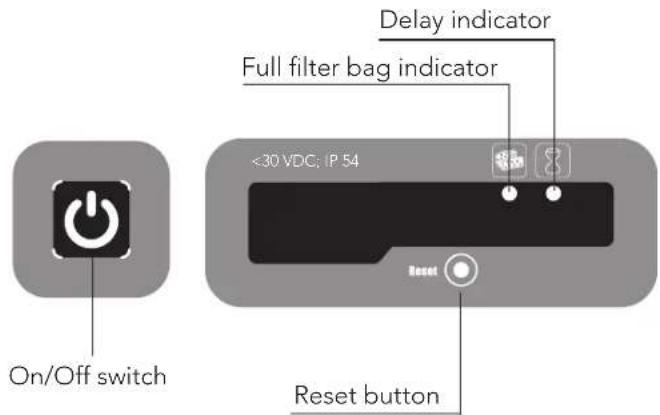
text_image
On/Off switch <30 VDC; IP 54 Delay indicator Full filter bag indicator Reset button
text_image
Diagram of a remote control device with labeled buttons and function icons, showing 'OK' status indicator.natural_image
Line drawing of a cleaning or cleaning tool with wheels and handle (no text or symbols)| 1 | DIN 7985 A2 M5X35 | x2 | |
| 2 | DIN 127B A2 M5 | x2 | |
| 3 | DIN 1587 A2 M5 | x2 | |
| 4 | WN 1412 A2 KA50X16 | x6 |
natural_image
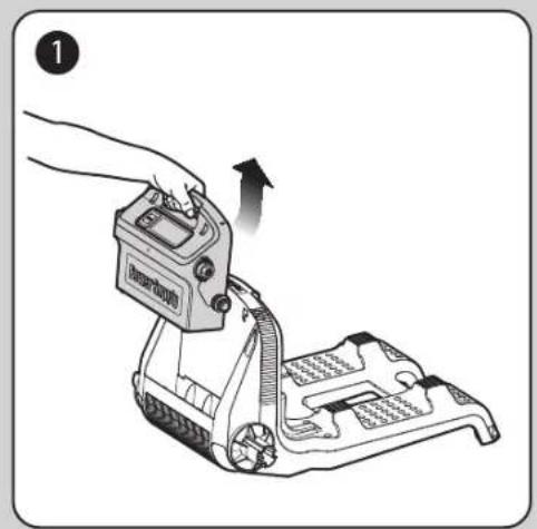
Illustration of a hand using a device to lift a mechanical component (no text or symbols visible)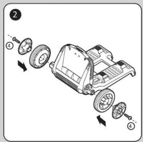
text_image
Diagram of a car chassis with labeled parts and directional arrows indicating assembly or disassembly.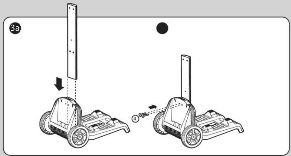
text_image
3a 4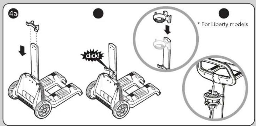
text_image
4a * For Liberty models click!
natural_image
Line drawing of a mobile phone with wheels and a vertical-mounted tower, no text or symbols present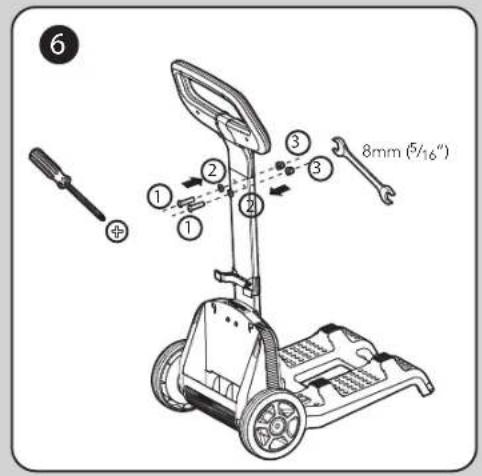
text_image
6 ① ② ③ ④ ⑤ 8mm (5/16")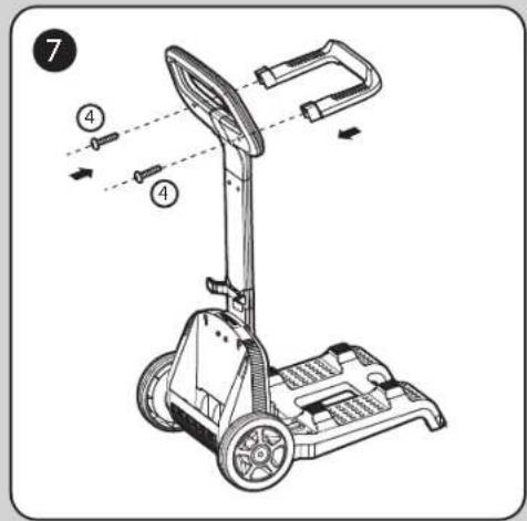
text_image
Technical diagram of a mobile phone with labeled parts and directional arrows indicating motion or assembly.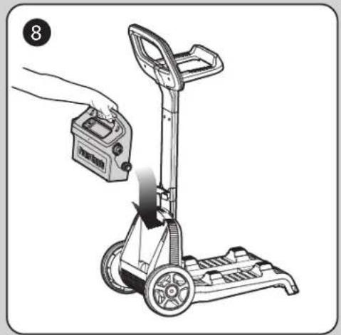
natural_image
Illustration of a hand holding a battery next to a manual pallet jack (no text or symbols visible)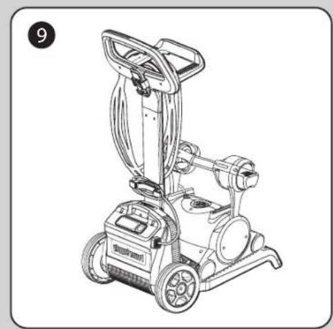
natural_image
Line drawing of a portable electric vacuum cleaner with wheels and control panel (no text or symbols)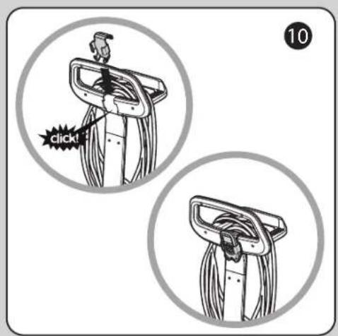
text_image
10 click!


Dolphin Classic 5 / Top 5 Pool Cleaner