
122RJ - Grass trimmer HUSQVARNA - Free user manual and instructions
Find the device manual for free 122RJ HUSQVARNA in PDF.

| Product type | Grass trimmer / brushcutter, petrol-powered |
| Brand | Husqvarna |
| Model | 122RJ |
| Power source | 2-stroke engine, petrol/oil mixture (50:1, 2%) |
| Displacement | 21.7 cm³ |
| Output power | 0.6 kW |
| Max power speed | 7 800 min⁻¹ |
| Idle speed | 2 800 – 3 200 min⁻¹ |
| Max output shaft rotation | 7 200 min⁻¹ |
| Fuel tank capacity | 0.34 L |
| Spark plug | HQT-4 (gap 0.5 mm) |
| Weight (without cutting equipment) | 4.8 kg |
| Guaranteed sound power level | 102 dB(A) |
| Sound pressure level at ear (grass blade) | 90 dB(A) |
| Cutting equipment | Grass blade (∅ 250 mm, ref. 580 44 66-06) |
| Handle | J-handle + harness |
| Safety devices | Throttle trigger lock, stop button, blade guard, line cutter, ear/eye protection recommended |
| Routine maintenance | Weekly external cleaning, idle speed check, gear housing greasing, monthly air filter cleaning, annual spark plug replacement |
| Spare parts | Original Husqvarna parts available (blade, head, spark plug, filter, etc.) |
| Repairability | User maintenance possible (blade, filter, spark plug); complex repairs at authorized service center |
Frequently Asked Questions - 122RJ HUSQVARNA
User questions about 122RJ HUSQVARNA
0 question about this device. Answer the ones you know or ask your own.
Ask a new question about this device
Download the instructions for your Grass trimmer in PDF format for free! Find your manual 122RJ - HUSQVARNA and take your electronic device back in hand. On this page are published all the documents necessary for the use of your device. 122RJ by HUSQVARNA.
USER MANUAL 122RJ HUSQVARNA
EN Operator's manual 5-17
2

6


8

9

10

13


14


17

natural_image
Line drawing of a person pushing a cart with a shovel and a tree nearby (no text or symbols)
20
natural_image
Simple line drawing of a mechanical tool or connector with a handle and lever (no text or symbols)19
natural_image
Illustration of a mechanical tool interacting with a base component (no text or symbols visible)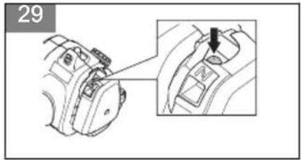
natural_image
Line drawing of a mechanical component with a central hub and flange (no text or symbols)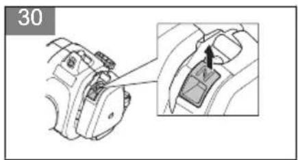
natural_image
Technical line drawing of a mechanical component with a rotating arrow and nut (no text or symbols)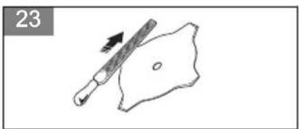
natural_image
Simple line drawing of a tool interacting with a shield-like shape, no text or symbols present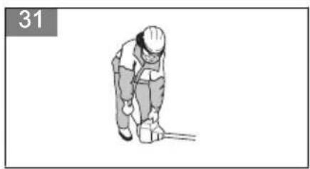
natural_image
Illustration of a person in work attire bending over a tool, no text or symbols present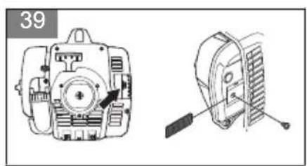
natural_image
Technical line drawings of a mechanical device with front and side views (no text or symbols)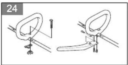
natural_image
Two technical line drawings of a mechanical clamp or clip assembly, showing no text or symbols.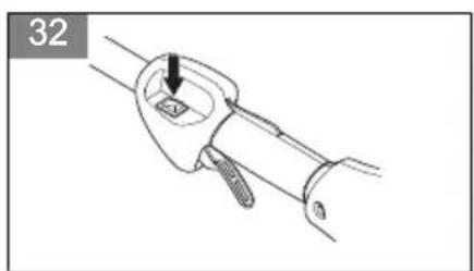
natural_image
Line drawing of a mechanical tool with a handle and screw base (no text or symbols)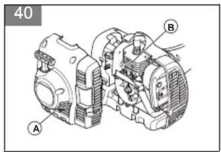
natural_image
Simple line drawing of a grassy field with a small tool or pestle (no text or symbols)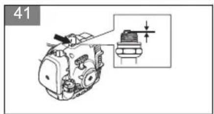
natural_image
Two identical mechanical components with a no-smoking symbol, no text or labels present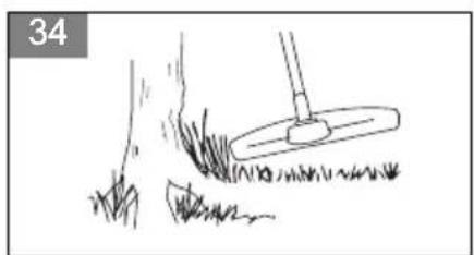
natural_image
Simple line drawing of a shovel digging grass with a tool, no text or symbols present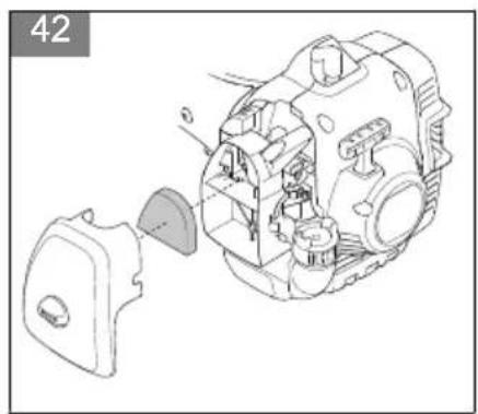
natural_image
Technical line drawing of a mechanical assembly with internal components (no text or symbols)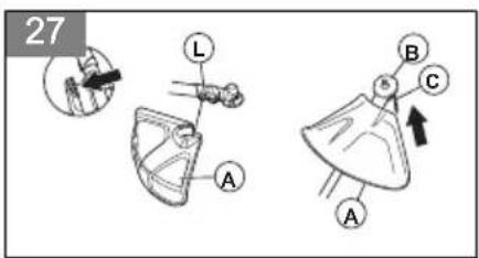
natural_image
Simple line drawing of a grassy field with a small mechanical component and a numbered label '35' (no text or symbols on the diagram itself)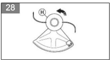
natural_image
Simple line drawing of a mechanical device with a circular head and curved blades, no text or symbols present.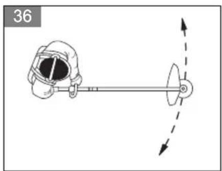
natural_image
Diagram of a person wearing a helmet and holding a pole with a rotating wheel, showing motion direction (no text or symbols)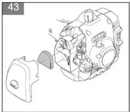
natural_image
Technical line drawing of a mechanical assembly with exploded view (no text or symbols)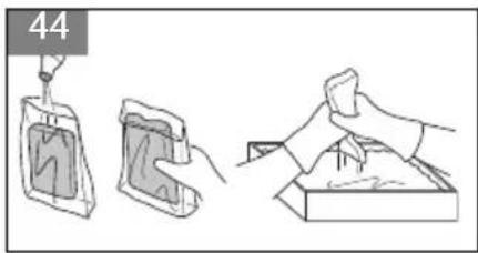
natural_image
Three-step illustration showing a bag being handled, a container being filled with liquid, and a hand cleaning a box (no text or symbols)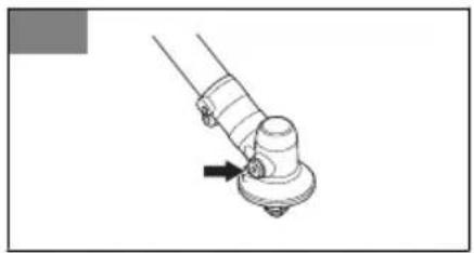
natural_image
Mechanical assembly diagram showing a lever mechanism with a directional arrow (no text or symbols)Contents
| Introduction | 5 |
| Safety | 6 |
| Assembly | 9 |
| Operation | 10 |
| Maintenance | 12 |
| Technical Data | 14 |
| Accessories | 15 |
| Declaration of Conformity | 16 |
| Appendix | 356 |
Introduction
Operator's manual
The initial language of this operator's manual is English. Operator's manuals in other languages are translations from English.
Overview
(Fig. 1)
- Trimmer head (only for 122L)
- Grease filler cap
- Bevel gear
- Cutting attachment guard
- Shaft
- Loop handle
- Throttle trigger
- Stop switch
- Throttle trigger lockout
- Spark plug cap, spark plug
- Starter housing
- Starter rope handle
- Fuel tank
- Air filter cover
- Primer bulb
- Choke control
- Drive disc
- Operator's manual
- Blade (only for 122RJ)
- J-handle (only for 122RJ)
- Harness (only for 122RJ)
- Harness clamp (only for 122RJ)
- Transport guard (only for 122RJ)
Symbols on the product
(Fig. 2) WARNING: Careless or incorrect use can result in serious injury or death to the operator or others.
(Fig. 3) Read this manual.
(Fig. 4) Use a protective helmet in locations where objects can fall on you. Use approved
| hearing protection. Use approved eye protection. | |
| (Fig. 5) | Use approved protective gloves. |
| (Fig. 6) | Use protective shoes/boots. |
| (Fig. 7) | The product can cause objects to eject which can cause damage to the eyes. |
| (Fig. 8) | The product can cause objects to eject which can cause damage to the eyes. |
| (Fig. 9) | Max. speed of the output shaft. |
| (Fig. 10) | Safe distance |
| (Fig. 11) | Be careful of blade thrust. |
| (Fig. 12) | Make sure that long hair is put up abo your shoulders. |
| (Fig. 13) | The arrows show the limits for the pos of the handle. |
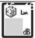
| (Fig. 14) | Noise emission to the environment label as per EU and UK directives and regulations, and New South Wales legislation Protection of the Environme Operations (Noise Control) Regulation 2017. The guaranteed sound power le of the product is specified in Technical Data on page 14 and on the label. |
| (Fig. 15) | The product agrees with the applicable EC directives. |
| (Fig. 16) | This product conforms to the applicable UK regulations. |
Note: Other symbols/decals on the product refer to certification requirements for other commercial areas.
Euro V Emissions

WARNING: Tampering with the engine voids the EU type-approval of this product.
Product liability
As referred to in the product liability laws, we are not liable for damages that our product causes if:
• the product is incorrectly repaired.
- the product is repaired with parts that are not from the manufacturer or not approved by the manufacturer.
- the product has an accessory that is not from the manufacturer or not approved by the manufacturer.
- the product is not repaired at an approved service center or by an approved authority.
Safety
Safety definitions
The definitions below give the level of severity for each signal word.

WARNING: Injury to persons.

CAUTION: Damage to the product.
Note: This information makes the product easier to use.
General safety instructions

WARNING: Read the warning instructions that follow before you use the product.
- Use the product correctly. Injury or death is a possible result of incorrect use. Only use the product for the tasks found in this manual. Do not use the product for other tasks.
- Obey the instructions in this manual. Obey the safety symbols and the safety instructions. If the operator does not obey the instructions and the symbols, injury, damage or death is a possible result.
- Do not discard this manual. Use the instructions to assemble, to operate and to keep your product in good condition. Use the instructions for correct installation of attachments and accessories. Only use approved attachments and accessories.
-
Do not use a damaged product. Obey the maintenance schedule. Only do the maintenance work that you find an instruction about in this manual. An approved service center must do all other maintenance work.
-
This manual cannot include all situations that can occur when you use the product. Be careful and use your common sense. Do not operate the product or do maintenance on the product if you are not sure about of the situation. Speak to a product expert, your dealer, service agent or approved service center for information.
- Examine the product daily for significant damage before each operation or when the product is hit by other objects or falls to ground. Refer to Maintenance schedule on page 12.
- Disconnect the spark plug cable before you assemble the product, put the product into storage or do maintenance.
- Do not use the product if it is changed from its initial specification. Do not change a part of the product without approval from the manufacturer. Only use parts approved by the manufacturer. Injury or death is a possible result of incorrect maintenance.
- Do not breathe in the fumes from the engine. Long-term inhalation of the engine's exhaust fumes is a health risk.
- Do not start the product indoors or near flammable material. The exhaust fumes are hot and can contain a spark which can start a fire. Not sufficient airflow can cause injury or death because of asphyxiation or carbon monoxide.
- When you use this product the engine makes an electromagnetic field. The electromagnetic field can cause damage to medical implants. Speak to your physician and medical implant manufacturer before you operate the product.
- Do not let a child operate the product. Do not let a person without knowledge of the instructions operate the product.
- Make sure that you always monitor a person, with decreased physical capacity or mental capacity, that uses the product. A responsible adult must be there at all times.
-
Lock the product in an area that children and unapproved persons cannot access.
-
The product can eject objects and cause injuries. Obey the safety instructions to decrease the risk of injury or death.
- Do not go away from the product when the engine is on.
- The operator of the product is responsible if an accident occurs.
- Make sure that parts are not damaged before you use the product.
- Make sure that you are at minimum 15 m (50 ft) away from other persons or animals before you use the product. Make sure that persons in the adjacent area know that you will use the product.
- Refer to national or local laws. They can prevent or decrease the operation of the product in some conditions.
- Do not use the product if you are fatigued, ill, or influenced by alcohol, drugs or medicine. They can have effects on your vision, alertness, coordination or judgment.
Safety instructions for operation
- Make sure the product is fully assembled before you use it.
- Before a start, move the product 3 m (10 ft) away from the position where you filled the fuel tank. Put the product on a flat surface. Make sure that the cutting attachment does not touch the ground or other objects.
- The product can cause objects to eject, which can cause damage to the eyes. Always use an approved eye protection when you operate the product.
- Be careful, a child can come near the product without your knowledge during operation.
- Do not operate the product if there are persons in the work area. Stop the product if a person goes into the work area.
- Make sure that you are always in control of the product. Make sure that you change the operation positions and take planned rests during operation of the product.
- Do not use the product if you cannot receive aid if an accident occurs. Always make sure others know you will operate the product before you start to operate the product.
- Do not turn with the product before you make sure that no persons or animals are in the safety area.
- Remove all unwanted materials from the work area before you start. If the cutting attachment hits an object, the object can eject and cause injury or damage. Unwanted material can wind around the cutting attachment and cause damage.
- Do not use the product in bad weather (fog, rain, strong winds, risk of lightning or other weather conditions.). Dangerous conditions (such as slippery surfaces) can occur because of bad weather.
- Make sure that you can move freely and work in a stable position.
(Fig. 17)
- Make sure that you cannot fall when you use the product. Do not tilt when you operate the product.
• Always hold the product with your two hands. Hold the product on the right side of your body.
(Fig. 18)
- Operate the product with the cutting attachment below your waist.
- If the choke control is in the choke position when the engine starts, the cutting attachment starts to turn.
- Do not touch the bevel gear after the engine stops. The bevel gear is hot after the engine stops. Hot areas can cause injury.
- Stop the engine before you move the product.
- Do not put down the product with the engine on.
- Before you remove the unwanted materials from the product, stop the engine and wait until the cutting attachment stops. Let the cutting attachment stop before you or an aid remove the cut material.
• Overexposure to vibration can lead to circulatory damage such as white finger disease or nerve damage in people who have impaired circulation. Contact your doctor if you experience symptoms of overexposure to vibration. These symptoms include numbness, loss of feeling, tingling, pricking, pain, loss of strength, changes in skin color or condition. These symptoms normally appear in the fingers, hands or wrists.
Personal protective equipment

WARNING: Read the warning instructions that follow before you use the product.
• Always use correct personal protective equipment when you operate the product. The personal protective equipment does not erase the risk of injury. The personal protective equipment decreases the grade of injury if an accident occurs.
• Always use an approved eye protection while you operate the product.
- Do not operate the product with bare feet or with open shoes. Always use heavy-duty slip-resistant boots.
- Use heavy, long pants.
- Use a helmet if it is possible that objects fall on your head.
• Always use approved ear protection while you operate the product. Noise for a long period can cause noise-induced hearing loss.
- Make sure that you have a first aid kit near.
- Use gloves when necessary, for example when you attach, examine or clean the cutting equipment. Gloves also help prevent circulatory or nerve damage to the hand and fingers caused by vibration.
Protective devices on the product
- Make sure that you regularly do the maintenance to the product.
• The life of the product increases.
- The risk of accidents decreases.
Let an approved dealer or an approved service center regularly examine the product to do adjustments or repairs.
- Do not use a product with damaged protective equipment. If the product is damaged, speak to an approved service center.
Throttle trigger lockout
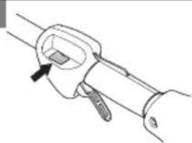
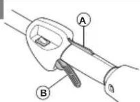
The throttle trigger lockout locks the throttle trigger. (Fig. 19)
Push the throttle trigger lockout (A) to release the throttle trigger (B). When you release the handle, the throttle trigger lockout and the throttle trigger go back to their initial positions.
- Make sure that the throttle trigger (B) is locked at idle when you release the throttle trigger lockout (A).
- Push the throttle trigger lockout (A) and make sure that it goes back to its initial position when you release it.
- Push the throttle trigger (B) and make sure that it goes back to its initial position when you release it.
Start the engine, and then apply full throttle. Release the throttle trigger and examine if the cutting attachment stops. If the cutting attachment turns with the throttle in the idle position, examine the idle adjustment screw of the carburetor.
Stop switch
Start the engine. Make sure that the engine stops when you move the stop switch to the stop position.
(Fig. 20)
Cutting attachment guard
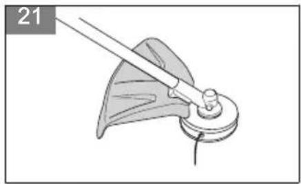
The cutting attachment guard prevents a loose object to eject in the direction of the operator. (Fig. 21)
Examine the cutting attachment guard for damage and replace if it is damaged. Only use the approved guard for the cutting attachment.
Muffler
- Do not use an engine with a damaged muffler. A damaged muffler increases the noise level and the risk of fire. Keep a fire extinguisher near.
- Examine regularly that the muffler is attached to the product.
-
Do not touch the engine or the muffler when then engine is on. Do not touch the engine or the muffler for a while after the engine stops. Hot surfaces can cause injuries.
-
A hot muffler can cause a fire. Be careful, if you use the product near flammable liquids or fumes.
- Do not touch the parts in the muffler, if the muffler is damaged. The parts can contain some carcinogenic chemicals.
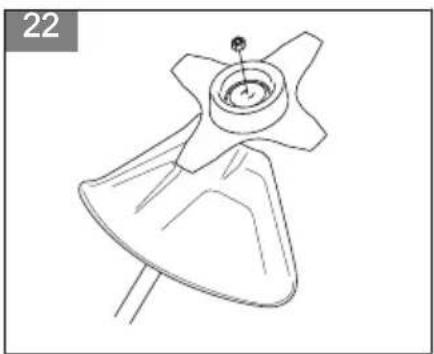
Locknut
The locknut is used to lock some types of cutting attachment.
(Fig. 22)
When you install the locknut, tighten it in the opposite direction to operation direction of the cutting attachment.
Cutting attachment

WARNING: Read the warning instructions that follow before you use the product.
- Do the regular maintenance. Let an approved service center regularly examine the cutting attachment to do adjustments or repairs.
- The performance of the cutting attachment increases.
- The life of the cutting attachment increases.
• The risk of accidents decreases. - Only use an approved cutting attachment guard. Refer to Accessories on page 15.
- Do not use a damaged cutting attachment.
Grass trimmer head
- Make sure that you wind the grass trimmer line tightly and equally around the drum to decrease the vibration.
- Use only the approved grass trimmer heads and grass trimmer lines. Refer to Accessories on page 15.
- Use a correct length of the grass trimmer line. A long grass trimmer line uses more engine power than a short grass trimmer line.
- Make sure that the cutter on the cutting attachment guard is not damaged.
- Soak the grass trimmer line in water for 2 days before you attach the grass trimmer line to the product. This increases the life of the grass trimmer line.
- Refer to the instructions for the cutting attachment to use the correct procedure to load the cord and the correct cord diameter.
Grass blades and grass cutters
- Use the product with an approved grass blade. Do not use a grass blade without proper installation of all required parts. Make sure that the installation is done correctly and that the proper parts are used. Inproper installation may cause the blade to fly off and seriously injure the operator or the bystanders.
- Wear protective gloves when you handle or do maintenance on the blade.
- Use head protection when you operate a product with a grass blade.
- Grass blades and grass cutters are used to cut rough grass.
- A grass blade can cause injury while it continues to spin after the engine is stopped or the throttle trigger is released. Make sure that the grass blade has completely stopped rotating before any maintenance.
- Stop the engine before you do work on the cutting attachment. Make sure the cutting attachment fully stops. Disconnect the lead from the spark plug.
- Only use an approved cutting attachment or a correctly sharpened blade.
- Keep the teeth of the blade correctly sharpened. (Fig. 23)
- Do not use a damaged cutting attachment.
- Attach the transport guard to the grass blade when you transport or store the product.
Blade thrust
- A blade thrust is a sudden movement of the product to the side, forward or rearward. A blade thrust occurs when the grass blade or saw blade hits an object that cannot be cut. In areas where it is not easy to see the material being cut the risk of blade thrust increases.
- When a blade thrust occurs, there is a risk that the product or the operator moves out of position. A blade that moves can hit bystanders and there is a risk of injuries.
- If a blade is bent, has cracks, is broken or damaged, discard the blade.
- Use a sharp blade. The risk of blade thrust increases when a blade is not sharp.
Fuel safety
- Do not start the product if there is fuel or engine oil on the product. Remove the unwanted fuel/oil and let the product dry. Remove unwanted fuel from the product.
- If you spill fuel on your clothing, change clothing immediately.
-
Do not get fuel on your body, it can cause injury. If you get fuel on your body, use a soap and water to remove the fuel.
-
Do not start the engine if you spill oil or fuel on the product or on your body.
- Do not start the product if the engine has a leak. Examine the engine for leaks regularly.
- Be careful with fuel. Fuel is flammable and the fumes are explosive and can cause injuries or death.
- Do not breathe in the fuel fumes, it can cause injury. Make sure that there is a sufficient airflow.
- Do not smoke near the fuel or the engine.
- Do not put warm objects near the fuel or the engine.
- Do not add the fuel when the engine is on.
- Make sure that the engine is cool before you refuel.
- Before you refuel, open the fuel tank cap slowly and release the pressure carefully.
- Do not add fuel to the engine in an indoor area. Not sufficient airflow can cause injury or death because of asphyxiation or carbon monoxide.
- Tighten the fuel tank cap carefully or a fire can occur.
- Move the product at a minimum of 3 m (10 ft) from the position where you filled the tank before a start.
- Do not put too much fuel in the fuel tank.
- Make sure that a leak cannot occur when you move the product or fuel container.
- Do not put the product or a fuel container where there is an open flame, spark or pilot light. Make sure that the storage area does not contain an open flame.
- Only use approved containers when you move the fuel or put the fuel into storage.
- Empty the fuel tank before long-term storage. Obey the local law on where to dispose fuel.
- Clean the product before long-term storage.
- Remove the spark plug cable before you put the product into storage to make sure that the engine does not start accidentally.
Safety instructions for maintenance
- If you cannot adjust the idle speed to make the cutting attachment stop, speak to your service center. Do not use the product until the product is correctly adjusted or repaired.
Assembly

WARNING: Read the safety chapter before you assemble the product.
To attach the loop handle
- Attach the loop handle to the shaft in compliance with the illustration and tighten. (Fig. 24)
- Make sure that the loop handle attaches between the arrows on the shaft.
To attach the J-handle

WARNING: Do not use saw blades when you install the J-handle. Use only grass blades/grass cutters or trimmer heads/plastic blades.
- Attach the J-handle to the loop handle in compliance with the illustration and tighten. (Fig. 24)
To install the harness clamp
- Put the top harness clamp on the shaft. Put the low harness clamp below the shaft.
- Align the screws in the top and low harness clamp.
- Install two screws into the screw holes.
- Tighten the screws to connect the harness clamp.
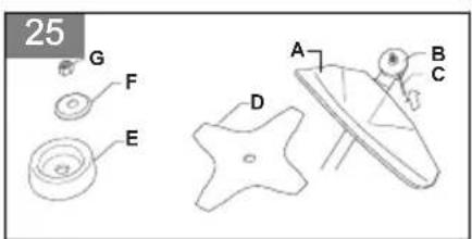
To install a blade guard, grass blade and grass cutter

CAUTION: Only use the approved guard for the blades. See Accessories on page 15.
- Attach the blade guard/cutting attachment guard (A) onto the shaft and tighten with the bolt. (Fig. 25)
- Install the drive disc (B) on the output shaft.
- Turn the output shaft until one of the holes in the drive disc aligns with the related hole in the gear housing.
- Put the hex key (C) in the hole to lock the shaft.
- Put the blade (D), support cup (E) and support flange (F) on the output shaft.
- Install the nut (G). Torque the nut to 35-50 Nm (26-36 ft/lb). Hold the shaft of the wrench near the blade guard as much as possible. To tighten the nut, you must turn the wrench in the opposite direction of rotation.
Note: Left hand thread.
To install blades and trimmer heads

WARNING: Only use the approved guard for the blades. See Accessories on page 15. A damaged guard can cause injury.

WARNING: If you operate the product with a grass blade, first install the correct handlebar, blade guard and harness.

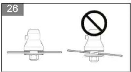
WARNING: If you do not install the blades correctly, it can cause injury.
- Make sure that the lifted section on the drive disc/support flange engages correctly in the center hole of the blades.
- Install the blades. (Fig. 26)
To assemble the cutting attachment
To attach the cutting attachment guard and the trimmer head (straight shaft)
- Attach the cutting attachment guard (A) to the shaft with the bolt (L).
- Attach the drive disc (B) to the output shaft.
- Turn the output shaft until the hole in the drive disc aligns with the hole in the gear housing.
- Put a small screwdriver (C) in the hole to lock the shaft. (Fig. 27)
- Turn the trimmer head (H) counterclockwise to tighten the trimmer head to the gearbox. (Left hand threads.) (Fig. 28)
Operation

WARNING: Read and understand the safety chapter before you operate the product.
Fuel
To use fuel

CAUTION: This product has a two-cycle engine. Use a mixture of gasoline and two-cycle engine oil. Make sure to use the correct quantity of oil in the mixture.
Incorrect ratio of gasoline and oil can cause damage to the engine.
Gasoline

CAUTION: Do not use gasoline with an octane number less than 90 RON (87 AKI). This can cause damage to the product.

CAUTION: Do not use gasoline with more than 10% ethanol concentration (E10). This can cause damage to the product.

CAUTION: Do not use leaded gasoline.
This can cause damage to the product.
• Always use new unleaded gasoline with a minimum octane number of 90 RON (87 AKI) and with less than 10% ethanol concentration (E10).
- Use gasoline with a higher octane number if you frequently use the product at continuously high engine speed.
• Always use a good quality unleaded gasoline/oil mixture.
Two-cycle engine oil
- Use only high quality two-cycle engine oil. Use only an air cooled engine oil.
- Do not use other types of oil.
• Mixture ratio 50:1 (2%)
| Gasoline | Oil |
| 1 U.S. Gal. 77 ml (2,6 oz) | |
| 1 UK Gal. 95 ml (3,2 oz) | |
| 5 l 100 ml (3,4 oz) |
To make the fuel mixture
Note: Always use a clean fuel container when you mix the fuel.
Note: Do not make more than 30 days quantity of fuel mixture.
- Add half of the gasoline quantity.
- Add the full quantity of oil.
- Shake the fuel mixture to mix the contents.
- Add the remaining gasoline quantity.
- Shake the fuel mixture to mix the contents.
- Fill the fuel tank.
To add fuel
- Always use a fuel container with an antispill valve.
- If there is some fuel on the container, remove the unwanted fuel and let the container dry.
- Make sure that the area near the fuel tank cap is clean.
- Shake the fuel container before you add the fuel mixture to the fuel tank.
To start and stop
To examine before start
-
Examine the product for missing, damaged, loose or worn parts.
-
Examine the nuts, screws and bolts.
- Examine the blades.
- Examine the locknut. Make sure that the locknut has a minimum locking force of 1.5 Nm (1,1 ft lb). Torque the locknut to 35-50 Nm (26-36 ft lb).
- Examine the air filter.
- Examine the throttle trigger lockout and the throttle control.
- Examine the stop switch.
- Examine the product for fuel leaks.
To start a cold engine
- Push the primer bulb 10 times. (Fig. 29)
- Pull the choke control up. (Fig. 30)
- Hold the body of the product on the ground with your left hand. (Fig. 31) Do not step on the product. Pull the starter rope handle slowly until you feel some resistance. Then pull the starter rope handle with force.
Note: Do not pull the throttle trigger while you start the engine.
- Continue to pull the starter rope handle until the engine starts or tries to start. If the engine starts or tries to start, push the choke control down.
- If the engine starts, push the throttle trigger lightly and let the engine run 60 seconds to become warm. If the engine does not start, pull the starter rope handle until the engine starts. Then push the throttle trigger lightly and let the engine run 60 seconds to become warm.

CAUTION: Do not pull the starter rope until it stops. Do not let go of the starter rope when it is fully extended. Release the starter rope slowly. Failure to obey these instructions can cause damage to the engine.
To start a warm engine
- Push the primer bulb 10 times.
- Pull the starter rope until the engine starts.
To stop the product
- Push the stop switch to stop the engine. (Fig. 32)
Note: The stop switch automatically goes back to its initial position.
To operate the grass trimmer

CAUTION: Make sure that you slow the engine to idle speed after each operation. A
Note: Clean the cover of the trimmer head when you attach a new trimmer line to prevent vibrations. Examine other parts of the trimmer head and clean if it is necessary.
To trim the grass
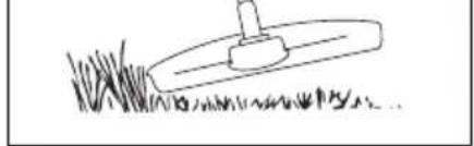
- Hold the trimmer head immediately above the ground at an angle. Do not push the trimmer line into the grass. (Fig. 33)
- Decrease the length of the trimmer line by 10-12 cm / 4-4.75 in.
- Decrease the engine speed to decrease the risk of damage to plants.
- Use 80 % throttle when you cut grass near objects. (Fig. 34)
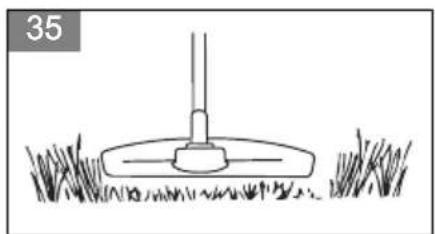
To cut the grass
- Make sure that the trimmer line is parallel to the ground when you cut the grass. (Fig. 35)
- Do not push the trimmer head to the ground. This can cause damage to the product.
- Move the product from side to side when you cut grass. Use full speed. (Fig. 36)
To clear grass with a grass blade
- Grass blades and grass cutters must not be used on woody stems.
- A grass blade is used for all types of tall or coarse grass.
- The grass is cut down with a sideways, swinging movement, where the movement from right-to-left is the clearing stoke and the movement from left-to-right is the return stoke. Let the left-hand side of the blade (between 8 and 12 o'clock) do the cutting.
- if the blade is angled to the left when clearing grass, the grass will collect in a line, which makes it easier to collect, e.g. by raking.
- Try to work rhythmically. Stand firmly with your feet apart. Move forward after the return stoke and stand firmly again.
- Let the support cup rest lightly against the ground. It is used to protect the blade from hitting the ground.
- Reduce the risk of material wrapping around the blade by always work at full throttle and avoid the previously cut material during the return stoke.
- Stop the engine, unclip the harness and place the machine on the ground before you start to collect the cut material.
Maintenance

WARNING: Read and understand the safety chapter before you clean, repair or do maintenance on the product.
Maintenance schedule
Make sure that you obey the maintenance schedule. The intervals are calculated from daily use of the product. The intervals are different if you do not use the product each day. Only do the maintenance work that is found in this manual. Speak to an approved service center about other maintenance work not found in this manual.
Weekly maintenance
- Clean the external surfaces.
- Examine the idle speed.
- Examine the bevel gear grease.
Monthly maintenance
- Examine the starter rope handle and the starter rope.
Yearly maintenance
- Examine the spark plug.
-
Clean the external surfaces of the carburetor and its adjacent areas.
-
Clean the cooling system.
- Examine the spark arrester screen.
- Examine the fuel filter.
- Examine the fuel hose for damage.
- Examine all cables and connections.
50 hours maintenance
- Have an approved service center repair or replace the muffler.
To adjust the idle speed
- Make sure that the air filter is clean and the air filter cover is attached before you adjust the idle speed.
- Adjust the idle speed with the idle adjustment screw T which is identified with "T" mark.
-
The idle speed is correct when the engine operates smoothly in all positions. The idle speed must be below the speed when the cutting attachment starts to turn.
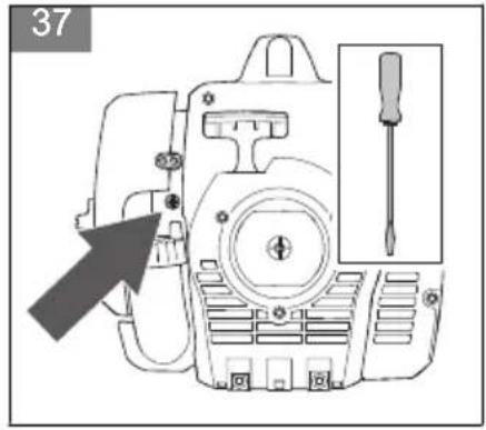
-
Turn the idle adjustment screw clockwise until the cutting attachment starts to turn. (Fig. 37)
- Turn the idle adjustment screw counterclockwise until the cutting attachment stops.
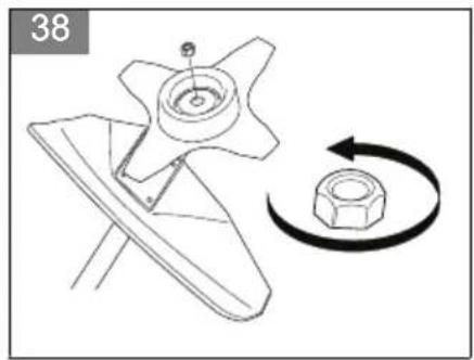
To remove the locknut

CAUTION: Replace the locknut when you use it for approximately 10 times.
- Remove the locknut in the direction as the cutting attachment turn. (Fig. 38)
Note: The locknut has a left thread.
- Examine that you cannot turn the nylon lining of the locknut with your hands. The nylon lining must supply a minimum resistance of 1.5 Nm (1,1 ft lb).
- Tighten the locknut with the socket wrench.
To do maintenance on the spark arrester screen
Use a wire brush to clean the spark arrester screen. (Fig. 39)
To clean the cooling system
Clean the parts of the cooling system with a brush.
(Fig. 40)
The cooling system include the air intake on the starter (A) and the cooling fins on the cylinder (B).
To examine the spark plug

CAUTION: Use the recommended spark plug. Make sure that the replacement is the same as the manufacturer supplied part. An incorrect spark plug can cause damage to the product. Make sure that the spark plug is installed with a suppressor. Speak to your servicing dealer for more information.
- Examine the spark plug when:
a) the engine is low on power.
b) the engine is not easy to start.
c) the engine does not operate correctly at idle speed.
- If, the engine is not easy to start or operate, examine the spark plug for unwanted materials. To decrease the risk of unwanted material on the spark plug electrodes:
a) make sure that the idle speed is correctly adjusted.
b) make sure that the fuel mixture is correct.
c) make sure that the air filter is clean.
-
Clean the spark plug if it is dirty. Make sure that the electrode gap is correct. Refer to Technical Data on page 14. (Fig. 41)
-
Replace the spark plug when it is necessary.
To do the maintenance to the air filter
To clean the air filter
- Remove the air filter cover and remove the air filter. (Fig. 42)
- Clean the air filter with warm soap water. Make sure that the air filter is dry before you install it.
- Replace the air filter if it is too dirty to fully clean it. Always replace a damaged air filter.
- If your product has a foam air filter, apply air filter oil. Only apply air filter oil to a foam filter. Do not apply oil to a felt filter.
To apply air filter oil to the air filter

CAUTION: Always use special air filter oil on foam air filters. Do not use other types of oil.

WARNING: Do not get oil on your body.
- Remove the air filter cover and remove the air filter. (Fig. 43)
- Put the air filter in a plastic bag.
- Put the air filter oil in the plastic bag. (Fig. 44)
- Push the plastic bag to make sure the oil supplies equally across the air filter.
- Push on the air filter, while in the bag, to remove the air filter oil that is not necessary. Remove the air filter from the bag.
- Install the air filter.
To add grease to the bevel gear
Make sure that the bevel gear is filled 3/4 full with bevel gear grease.
(Fig. 45)
To sharpen grass cutters and grass blades
- Sharpen grass cutters and grass blades with a single-cut flat file.
- Sharpen all edges of the grass cutters and blades equally to keep the balance. (Fig. 23)
Technical Data
| unit 122L 122RJ | |||
| Engine | |||
| Cylinder displacement cm | 3 | 21.7 21.7 | |
| Electrode gap mm 0.5 0.5 | |||
| Fuel tank volume l/cm | 3 | 0.34/343 0.34/343 | |
| Idling speed min | -1 | 2800 - 3200 2800 - 3200 | |
| Maximum power speed min | -1 | 7800 7800 | |
| Power output kW 0.6 0.6 | |||
| Spark plug HQT-4 672201 HQT-4 672201 | |||
| Maximum output shaft rotation | min-1 | 7200 7200 | |
| Noise and Vibration Data | |||
| Equivalent vibration level (ahv, eq), equipped with grass blade, front handle - see note 1 | m/s2 | N/A | 2.76 |
| Equivalent vibration level (ahv, eq), equipped with grass blade, rear handle - see note 1 | m/s2 | N/A | 2.88 |
| Equivalent vibration level (ahv, eq) equipped with trim-mer head, front handle - see note 1 | m/s2 | 2.95 N/A | |
| Equivalent vibration level (ahv, eq) equipped with trim-mer head, rear handle - see note 1 | m/s2 | 2.66 N/A | |
| Sound power level, guaranteed (LWA) - see note 2 | dB(A) | 102 | 102 |
| Sound power level, measured - see note 2 | dB(A) | 97 | 99 |
| Sound pressure level at operator's ear, equipped with grass blade - see note 3 | dB(A) | N/A | 90 |
| Sound pressure level at operator's ear, equipped with trimmer head - see note 3 | dB(A) | 85 | N/A |
| Product Dimensions | |||
| Weight (excluding cutting equipment) | kg | 4.7 4.8 | |
| Note 1: Reported data for equivalent vibration level has a typical statistical dispersion (standard deviation) of 1.5 m/s2. Note 2: Noise emissions in the environment measured as sound power (LWA) in conformity with EC directive 2000/14/ EC. Reported sound power level for the machine has been measured with the original cutting attachment that gives the highest level. The difference between guaranteed and measured sound power is that the guaranteed sound power also includes dispersion in the measurement result and the variations between different machines of the same model according to Directive 2000/14/EC. Note 3: Reported data for equivalent sound pressure level for the machine has a typical statistical dispersion (standard deviation) of 3.5 dB (A). | |||
Accessories
| 122RJ | ||
| Approved accessories Type Cutting attachment guard | ||
| Threaded shaft (M10L) | ||
| Grass blade/grass cutter Grass 255-4 (∅ 250) 580 44 66-06 | ||
| 122L | ||
| Approved accessories Type Cutting attachment guard | ||
| Trimmer head T25 (∅ 2.0 - 2.4 mm) 580 44 66-06 | ||
Declaration of Conformity
EU Declaration of Conformity
We, Husqvarna AB, SE 561 82 Huskvarna, Sweden, tel: +46-36-146500, declare under our sole responsibility that the product:
| Description Gasoline Grass Trimmer / | Brushcutter |
| Brand Husqvarna | |
| Type / Model 122L 122RJ | |
| Identification Serial number dating 2023 and onwards | |
complies fully with the following EU directives and regulations:
| Regulation Description | |
| 2006/42/EC “relating to machinery” | |
| 2014/30/EU “relating to electromagnetic compatibility” | |
| 2000/14/EC “relating to outdoor noise” | |
| 2011/65/EU “restriction of use of certain hazardous substances” |
Harmonized standards and/or technical specifications applied are as follows:
EN ISO 12100:2010, EN ISO 11806-1:2022, CISPR 12:2007+A1:2009, ISO 14982:2009, EN IEC 63000:2018
TUV Rheinland has carried out a voluntary examination on behalf of Husqvarna AB, providing AM 50596267 - Certificate of conformity to EC Council directive 2006/42/EC for machinery.
The certificate is applicable to all manufacturing locations and Countries of Origin, as stated on the product.
The supplied product conforms to the example that underwent examination.
On behalf of Husqvarna AB, SE 561 82 Huskvarna, SWEDEN, 2023-07-25
$$ \Delta \operatorname {d u} $$
Claes Losdal, R&D Manager, Husqvarna AB
Responsible for technical documentation

UK Declaration of Conformity
We, Husqvarna AB, SE 561 82 Huskvarna, Sweden,
tel: +46-36-146500, declare under our sole responsibility
that the product:
| Description Gasoline Grass Trimmer / | Brushcutter |
| Brand Husqvarna | |
| Type / Model 122L 122RJ | |
| Identification Serial number dating 2023 and onwards | |
complies fully with the following UK regulations:
| Description |
| The Supply of Machinery (Safety) Regulations 2008 |
| Electromagnetic Compatibility Regulations 2016 |
| The Noise Emission in the Environment by Equipment for use Outdoors Regulations 2001, schedule 8 |
| The Restriction of the use of Certain Hazardous Substances in Electrical and Electronic Equipment Regulations 2012 |
and that the following standards and/or technical specifications are applied:
EN ISO 12100:2010, EN ISO 11806-1:2022,
CISPR 12:2007+A1:2009, ISO 14982:2009, EN IEC
63000:2018
For information relating to noise emissions, refer to Technical Data on page 14.
Huskvarna, 2023-07-25
$$ \Delta \cdot 2 m $$
Claes Losdal, R&D Manager, Husqvarna AB
Responsible for technical documentation

UK Importer:
Husqvarna UK Ltd
Preston Road, Co. Durham
DL5 6UP
Съдържание
Claes Losdal, responsible R&D, Husqvarna AB
Responsable de la documentation technique

Sadržaj
Uvod.... 143
Sigurnost....144
Sastavljanje.... 147
Rad.... 148
Održavanje.... 150
Tehnički podaci....152
Dodatna oprema.... 153
Izjava o sukladnosti.... 154
Dodatak 356
Uvod
Afiar as lâminas e as cortadoras de relva

- Contents
- Introduction
- Operator's manual
- Overview
- (Fig. 1)
- Symbols on the product
- Euro V Emissions
- Product liability
- Safety
- Safety definitions
- General safety instructions
- Safety instructions for operation
- (Fig. 17)
- (Fig. 18)
- Personal protective equipment
- Protective devices on the product
- Throttle trigger lockout
- Stop switch
- Cutting attachment guard
- Muffler
- Locknut
- Cutting attachment
- Grass trimmer head
- Grass blades and grass cutters
- Blade thrust
- Fuel safety
- Safety instructions for maintenance
- Assembly
- To attach the loop handle
- To attach the J-handle
- To install the harness clamp
- To install a blade guard, grass blade and grass cutter
- To install blades and trimmer heads
- To assemble the cutting attachment
- Operation
- Fuel
- To use fuel
- Gasoline
- CAUTION: Do not use leaded gasoline.
- Two-cycle engine oil
- To make the fuel mixture
- To add fuel
- To start and stop
- To examine before start
- To start a cold engine
- To start a warm engine
- To stop the product
- To operate the grass trimmer
- To trim the grass
- To cut the grass
- To clear grass with a grass blade
- Maintenance
- Maintenance schedule
- Weekly maintenance
- Monthly maintenance
- Yearly maintenance
- hours maintenance
- To adjust the idle speed
- To remove the locknut
- To do maintenance on the spark arrester screen
- To clean the cooling system
- To examine the spark plug
- To do the maintenance to the air filter
- To clean the air filter
- To apply air filter oil to the air filter
- To add grease to the bevel gear
- To sharpen grass cutters and grass blades
- Declaration of Conformity
- EU Declaration of Conformity
- UK Declaration of Conformity
- Sadržaj
- Uvod
- Afiar as lâminas e as cortadoras de relva
Brand : HUSQVARNA
Model : 122RJ
Category : Grass trimmer