RCA 50 - Aquarium EDEN - Free user manual and instructions
Find the device manual for free RCA 50 EDEN in PDF.


User questions about RCA 50 EDEN
0 question about this device. Answer the ones you know or ask your own.
Ask a new question about this device
Download the instructions for your Aquarium in PDF format for free! Find your manual RCA 50 - EDEN and take your electronic device back in hand. On this page are published all the documents necessary for the use of your device. RCA 50 by EDEN.
USER MANUAL RCA 50 EDEN
EN Operating instructions
FR Notice d'emploi
natural_image
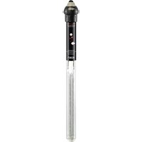
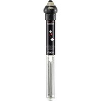
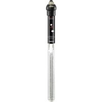
Four identical laboratory glassware pens with transparent tubes, each containing a small object (no visible text or labels)eden
Original-Anleitung.
Sicherheitshinweise
text_image
Technical diagram of a vertical cylindrical device with labeled components and exploded view, showing internal components and wiring connections.HUP0001
text_image
Diagram illustrating a mechanical or electrical device with labeled components and directional arrows indicating motion or flow.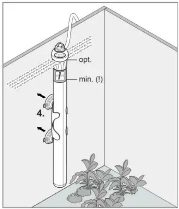
text_image
opt. min. (!) 4.HUP0005
VORSICHT
text_image
Diagram illustrating a cable installation or power system with labeled components and water flow indicatorsHUP0002
text_image
Diagram illustrating the use of a rotary switch device with labeled degrees and a water level indicator.HUP0006
Electrical connection
- Only connect the unit if the electrical data of the unit and the power supply match.
- Only plug the unit into a correctly installed outlet.
- The device is to be supplied through a residual current device (RCD) having a rated residual operating current not exceeding 30 mA.
- Protect open plugs and sockets from moisture.
Safe operation
- Disconnect all electrical devices in the water from the power supply before reaching into the water. Otherwise there is a risk of severe injuries or death by electrocution.
- Do not use the unit, if electrical lines or the housing are damaged.
- The supply cord cannot be replaced. If the cord is damaged, the appliance should be scrapped.
- Never pull on electric cables. In particular, never carry units on their cables.
- Route lines in such a way that they are protected from damage and do not present a tripping hazard.
- Do not use the unit together with chemicals, food, flammable, explosive substances or other liquids aside from water.
- This unit can be used by children aged 3 and above and by persons with reduced physical, sensory or mental capabilities or lack of experience and knowledge if they are supervised or have been instructed on how to use the unit in a safe way and they understand the hazards involved. Do not allow children to play with the unit. Only allow children to carry out cleaning and user maintenance under supervision.
- Never carry out technical changes to the unit.
- Only use original spare parts and accessories.
- Should problems occur, please contact the authorised customer service or EDEN.
Intended use
Only use the product described in this manual as follows:
- As a thermostat controlled aquarium heater.
- Indoors and for private aquarium-keeping purposes.
- While adhering to the technical specifications. (→ Technical data)
Product Description
text_image
Technical diagram of a vertical cylindrical device with labeled components and exploded view, showing internal components and wiring connections.HUP0001
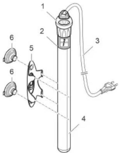
1 Heating head with temperature controller
2 Minimum immersion depth mark
3 Power cable
4 Bulb with heater
5 Holder
6 Suction cups
Symbols on the unit
IPX8

The unit is protected against the results of permanent immersion in water to a depth of 0.8 m.

Protection class II. The unit is securely disconnected from the power supply by a reinforced or double insulation.

Only use the unit in indoor spaces

Do not dispose of the unit with normal household waste.
Read the operating instructions.
Installation and connection
The desired water temperature can only be achieved if the heating capacity of the heater is suitable for the volume of water in the aquarium and is positioned in an area with good water circulation. (→ Recommended heating power)
- Ensure that the unit is immersed in water at least up to the minimum immersion depth marking.
- The unit can be completely immersed in water.
- Turn the temperature controller to the desired temperature value.
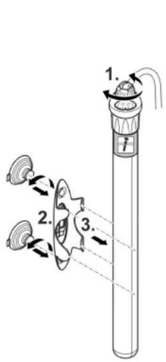
- Insert the supplied suction cups into the holder by twisting.
- Pay attention to the alignment of the tabs (they should point upwards or to the side).
- Clamp the holder to the unit.
- Position the unit with the heating element pointing towards the floor of the filled aquarium on a clean, smooth surface in an area with good water circulation.
text_image
Diagram illustrating a mechanical or fluid system with three labeled components and directional arrows indicating flow or movement.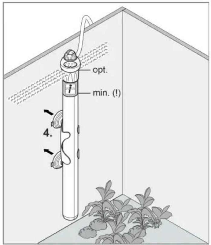
text_image
opt. min. (!) 4.HUP0005
CAUTION
Risk of burns from hot surface.
▶ Only switch on the heater when the bulb is submerged in water.
▶ Turn the heater off and let it cool down before removing it from the water.
- Wait approx. 30 minutes before switching on so that the thermostat can adjust to the temperature of the water.
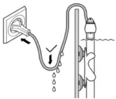
- Route the power connection cable such that it forms a drip loop!
Switching on: Connect the unit to the mains. The unit switches on immediately.
Switching off: Disconnect the unit from the mains.
text_image
Diagram illustrating a cable installation or water flow system with labeled components and directional arrows indicating flow direction.HUP0002
Checking the temperature values
i The heater switches on and off automatically in order to maintain the set temperature.
- A light in the glass bulb indicates that the heater is functioning.
- The light and heater are switched off when the set temperature is reached.
How to proceed:
- When the unit has been operating for about one day, check the water temperature with a precision thermometer.
- The measured temperature is lower than the set temperature: Check the water flow around the unit and, if necessary, move the unit to a different position where the water circulation is not obstructed by e.g. plants
- Measure the temperature again after some time.
- The temperature difference is still too great: Calibrate the unit. (→ Calibrating the unit)
- The measured temperature is higher than the set temperature: Calibrate the unit. (→ Calibrating the unit)
Calibrating the unit
- Calibration range: It is possible to calibrate the unit by plus 3^ C and minus 3^ C .
- The calibration controller protrudes out of the different-coloured temperature controller. There are 3 fixed positions in the plus and minus range. Each position corresponds to approx. 1 degree centigrade.
- Do not attempt to go outside the calibration range.
How to proceed:
- Use a screwdriver for the calibration or break the supplied tool out of the holder.
- Measured temperature is too high: Keep the temperature controller at the set value and move the calibration controller in the direction of - (minus).
- Measured temperature is too low: Keep the temperature controller at the set value and move the calibration controller in the direction of + (plus).
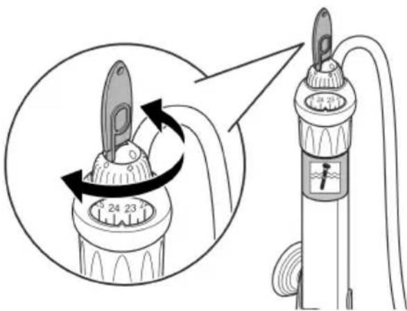
text_image
Diagram showing a rotary oil lamp mechanism with labeled parts and directional arrows indicating rotation.HUP0006
Maintenance and cleaning
If necessary, clean the unit with clear water using a soft sponge or cloth.
- Do not not use cleaning agents or chemical solutions.
Malfunction remedy
| Malfunction | Cause | Remedy |
| The water does not heat up. | No mains voltage | Check the mains voltage. |
| Unit defective | Replace unit | |
| Water does not reach the set temperature. | Insufficient water circulation | Check the temperature. |
| Unit is not calibrated. | Calibrate the unit. | |
| The heating capacity of the unit is not sufficient with regards to the ambient temperature or water volume to be heated up. | Select a suitable unit. |
Technical data Unit data
| EDEN RCA | 25 | 50 | 75 | 100 | |
| Connection voltage | V AC | 230 | 230 | 230 | 230 |
| Mains frequency | Hz | 50 | 50 | 50 | 50 |
| Power consumption | W | 25 | 50 | 75 | 100 |
| Length of power cable | m | 1.5 | 1.5 | 1.5 | 1.5 |
| Suitable for fresh water | ✓ | ✓ | ✓ | ✓ | |
| Suitable for salt water | ✓ | ✓ | ✓ | ✓ | |
| Temperature control | °C | +18 ... +32 | +18 ... +32 | +18 ... +32 | +18 ... +32 |
| Dimensions (∅ × H) | mm | 33 × 205 | 33 × 205 | 33 × 243 | 33 × 243 |
| Weight | kg | 0.20 | 0.20 | 0.20 | 0.22 |
| EDEN RCA | 150 | 200 | 250 | 300 | |
| Connection voltage | V AC | 230 | 230 | 230 | 230 |
| Mains frequency | Hz | 50 | 50 | 50 | 50 |
| Power consumption | W | 150 | 200 | 250 | 300 |
| Length of power cable | m | 1.5 | 1.5 | 1.5 | 1.5 |
| Suitable for fresh water | ✓ | ✓ | ✓ | ✓ | |
| Suitable for salt water | ✓ | ✓ | ✓ | ✓ | |
| Temperature control | °C | +18 ... +32 | +18 ... +32 | +18 ... +32 | +18 ... +3 |
| Dimensions (∅ × H) | mm | 33 × 315 | 33 × 315 | 33 × 370 | 33 × 370 |
| Weight | kg | 0.25 | 0.25 | 0.28 | 0.28 |
Recommended heating power
Recommended heating capacity depending on the volume of water V and the temperature difference T between the desired water temperature and the lowest ambient temperature.
| V | T | ||
| 5 °C | 10 °C | 15 °C | |
| ≤ 25 l | 25 W | 25 W | 75 W |
| ≤ 50 l | 50 W | 50 W | 100 W |
| ≤ 75 l | 50 W | 75 W | 150 W |
| ≤ 100 l | 75 W | 100 W | 200 W |
| ≤ 150 l | 100 W | 150 W | 300 W |
| ≤ 200 l | 150 W | 200 W | 2 × 200 W |
| ≤ 250 l | 200 W | 250 W | 2 × 250 W |
| ≤ 300 l | 250 W | 300 W | 2 × 300 W |
EN
Wear parts
- Suction cups
Disposal
NOTE
Do not dispose of this unit with household waste.
▶ Dispose of the unit by using the return system provided for this purpose.
▶ Should you have questions, please contact your local disposal company. They will give you information on how to correctly dispose of the unit.
▶ Render the unit unusable by cutting the cables.
text_image
Technical diagram of a vertical cylindrical device with labeled components and exploded view, showing internal components and wiring connections.FR
HUP0001
text_image
Diagram illustrating a cable installation or power system with labeled components and water flow indicatorsHUP0002
text_image
Diagram showing a device with a rotary knob and dial, illustrating the process of rotation or adjustment.HUP0006
| V | T | ||
| 5 °C | 10 °C | 15 °C | |
| ≤ 25 l | 25 W | 25 W | 75 W |
| ≤ 50 l | 50 W | 50 W | 100 W |
| ≤ 75 l | 50 W | 75 W | 150 W |
| ≤ 100 l | 75 W | 100 W | 200 W |
| ≤ 150 l | 100 W | 150 W | 300 W |
| ≤ 200 l | 150 W | 200 W | 2 ×200 W |
| ≤ 250 l | 200 W | 250 W | 2 × 250 W |
| ≤ 300 l | 250 W | 300 W | 2 × 300 W |
Pièces d'usure
- Ventouses
Recyclage
REMARQUE
text_image
Technical diagram of a vertical cylindrical device with labeled components and exploded view, showing internal components and wiring connections.HUP0001
text_image
Diagram illustrating a mechanical or fluid system with three labeled components and directional arrows indicating flow or movement.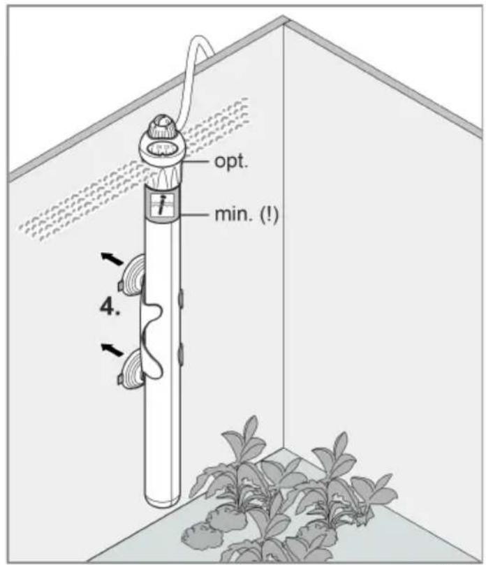
text_image
opt. min. (!) 4.HUP0005
Ingebruikname
text_image
Diagram illustrating a cable installation or power line with labeled components and water flow indicatorsHUP0002
text_image
Diagram showing a device with a rotary knob and dial, annotated with rotational arrows and numerical values.HUP0006
text_image
Technical diagram of a vertical cylindrical device with labeled components and exploded view, showing internal components and wiring connections.ES
HUP0001
text_image
Diagram illustrating a mechanical or electrical component with labeled parts and directional arrows indicating motion or assembly.
text_image
opt. min. (!) 4.HUP0005
Puesta en marcha
text_image
Diagram illustrating a water heating system with a power outlet, pipe, and water drop, showing fluid flow direction.HUP0002
text_image
Diagram showing a valve mechanism with numbered dial indicators and a close-up view of the valve assembly.HUP0006
| V | T | ||
| 5 °C | 10 °C | 15 °C | |
| ≤ 25 l | 25 W | 25 W | 75 W |
| ≤ 50 l | 50 W | 50 W | 100 W |
| ≤ 75 l | 50 W | 75 W | 150 W |
| ≤ 100 l | 75 W | 100 W | 200 W |
| ≤ 150 l | 100 W | 150 W | 300 W |
| ≤ 200 l | 150 W | 200 W | 2 ×200 W |
| ≤ 250 l | 200 W | 250 W | 2 × 250 W |
| ≤ 300 l | 250 W | 300 W | 2 × 300 W |
Piezas de desgaste
- Ventosas
Desecho
INDICACIÓN
text_image
Technical diagram of a vertical cylindrical device with labeled components and exploded view, showing internal components and wiring connections.HUP0001
text_image
Diagram illustrating a mechanical or electrical component with labeled parts and directional arrows indicating motion or assembly.
text_image
opt. min. (!) 4.HUP0005
text_image
Diagram illustrating a cable installation or water flow system with labeled components and directional arrows indicating flow direction.HUP0002
Verificar os valores de temperatura
text_image
Diagram illustrating the working principle of a pump, showing valve mechanism and speed reading with directional arrows.HUP0006
| V | T | ||
| 5 °C | 10 °C | 15 °C | |
| ≤ 25 l | 25 W | 25 W | 75 W |
| ≤ 50 l | 50 W | 50 W | 100 W |
| ≤ 75 l | 50 W | 75 W | 150 W |
| ≤ 100 l | 75 W | 100 W | 200 W |
| ≤ 150 l | 100 W | 150 W | 300 W |
| ≤ 200 l | 150 W | 200 W | 2 ×200 W |
| ≤ 250 l | 200 W | 250 W | 2 × 250 W |
| ≤ 300 l | 250 W | 300 W | 2 × 300 W |
Peças de desgaste
- Ventosas
text_image
Technical diagram of a vertical cylindrical device with labeled components and exploded view, showing internal components and wiring connections.IT
HUP0001
text_image
Diagram of a water pump or valve mechanism with labeled components and directional arrows indicating flow or movement.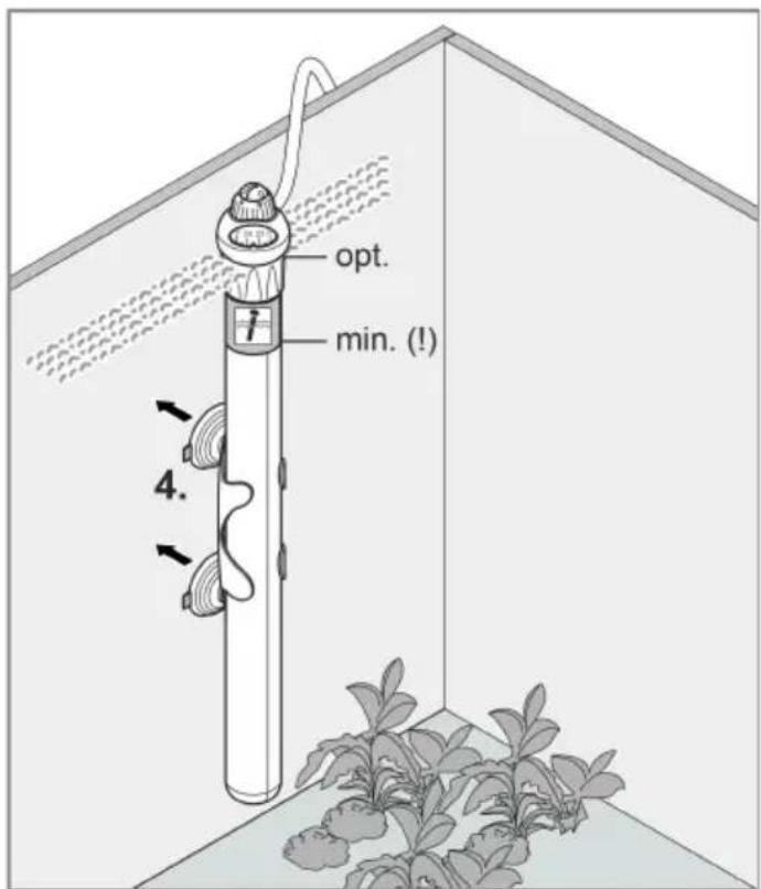
text_image
opt. min. (!) 4.HUP0005
Messa in funzione
text_image
Diagram illustrating a cable installation or power line with labeled components and water flow indicatorsHUP0002
text_image
Diagram showing a valve mechanism with numbered dial indicators and a close-up view of the valve assembly.HUP0006
| V | T | ||
| 5 °C | 10 °C | 15 °C | |
| ≤ 25 l | 25 W | 25 W | 75 W |
| ≤ 50 l | 50 W | 50 W | 100 W |
| ≤ 75 l | 50 W | 75 W | 150 W |
| ≤ 100 l | 75 W | 100 W | 200 W |
| ≤ 150 l | 100 W | 150 W | 300 W |
| ≤ 200 l | 150 W | 200 W | 2 ×200 W |
| ≤ 250 l | 200 W | 250 W | 2 × 250 W |
| ≤ 300 l | 250 W | 300 W | 2 × 300 W |
text_image
Technical diagram of a vertical cylindrical device with labeled components and exploded view, showing internal components and wiring connections.HUP0001
1 Varmehoved med temperaturstyring
2 Markering for min. neddykning
3 Netkabel
4 Glaskolbe med varmelegeme
5 Holder
6 Sugeskåle
text_image
Diagram illustrating a mechanical or electrical device with labeled components and directional arrows indicating motion or flow.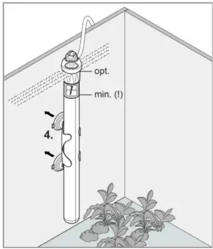
text_image
opt. min. (!) 4.HUP0005
Ibrugtagning
Tænd / sluk
! FORSIGTIG
text_image
Diagram illustrating a cable installation or water flow system with labeled components and directional arrows indicating flow direction.HUP0002
text_image
Diagram illustrating the working principle of a fuel pump, showing valve rotation and speed control mechanism.DA
HUP0006
| V | T | ||
| 5 °C | 10 °C | 15 °C | |
| ≤ 25 l | 25 W | 25 W | 75 W |
| ≤ 50 l | 50 W | 50 W | 100 W |
| ≤ 75 l | 50 W | 75 W | 150 W |
| ≤ 100 l | 75 W | 100 W | 200 W |
| ≤ 150 l | 100 W | 150 W | 300 W |
| ≤ 200 l | 150 W | 200 W | 2 ×200 W |
| ≤ 250 l | 200 W | 250 W | 2 × 250 W |
| ≤ 300 l | 250 W | 300 W | 2 × 300 W |
DA
Lukkedele
- Sugeskåle
Bortskaffelse
BEMÄRK
text_image
Technical diagram of a vertical cylindrical device with labeled components and exploded view, showing internal components and wiring connections.HUP0001
| 1 | Varmehode med temperaturregulator |
| 2 | Markering minimum nedsenkingsdybde |
| 3 | Strømkabel |
| 4 | Glasskolbe med oppvarming |
| 5 | Holder |
| 6 | Sugekopper |
text_image
Diagram illustrating a mechanical or electrical device with three labeled components and directional arrows indicating motion.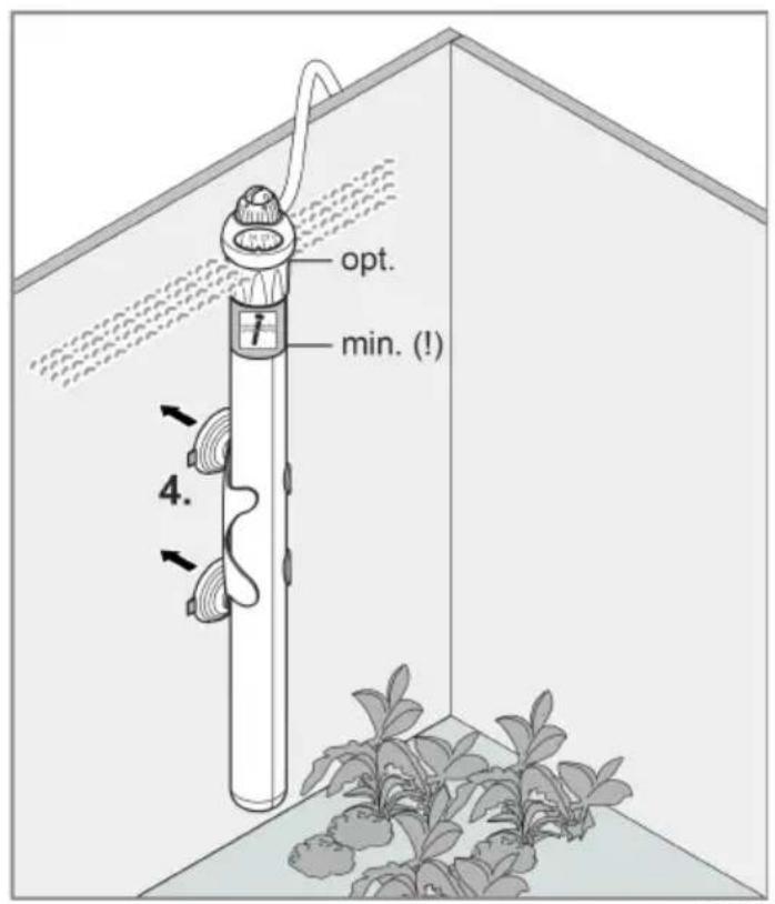
text_image
opt. min. (!) 4.HUP0005
Igangsetting
Slå av/på

FORSIKTIG
text_image
Diagram illustrating a cable installation or power line with labeled components and water flow indicatorsKontrollere temperaturverdiene
text_image
Diagram illustrating the working principle of a fuel pump, showing valve positioning and speed control mechanism.HUP0006
| V | T | ||
| 5 °C | 10 °C | 15 °C | |
| ≤ 25 l | 25 W | 25 W | 75 W |
| ≤ 50 l | 50 W | 50 W | 100 W |
| ≤ 75 l | 50 W | 75 W | 150 W |
| ≤ 100 l | 75 W | 100 W | 200 W |
| ≤ 150 l | 100 W | 150 W | 300 W |
| ≤ 200 l | 150 W | 200 W | 2 ×200 W |
| ≤ 250 l | 200 W | 250 W | 2 × 250 W |
| ≤ 300 l | 250 W | 300 W | 2 × 300 W |
Slitedeler
- Sugekopp
Kassering
MERK
text_image
Technical diagram of a vertical cylindrical device with labeled components and exploded view, showing internal components and wiring connections.HUP0001
text_image
Diagram illustrating a mechanical or electrical device with labeled components and directional arrows indicating motion or flow.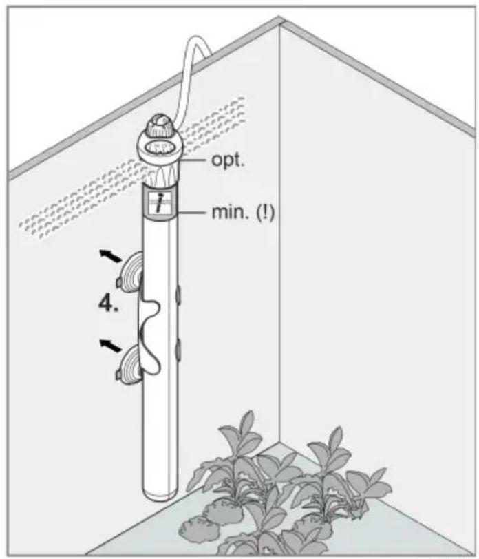
text_image
opt. min. (!) 4.HUP0005
Driftstart
text_image
Diagram illustrating a cable installation or power line with labeled components and water flow indicatorsHUP0002
text_image
Diagram showing a device with a rotary knob and dial, annotated with directional arrows and numerical values.SV
HUP0006
text_image
Technical diagram of a vertical cylindrical device with labeled components and exploded view, showing internal components and wiring connections.HUP0001
text_image
Diagram illustrating a mechanical or electrical device with labeled components and directional arrows indicating motion or assembly.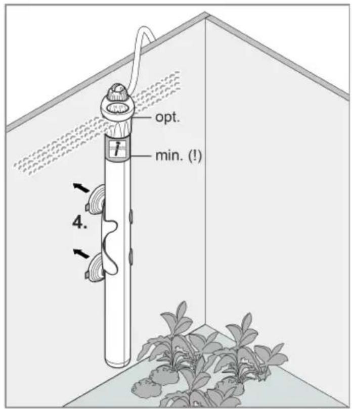
text_image
opt. min. (!) 4.HUP0005
HUOMIO
text_image
Diagram illustrating a cable installation or power line with labeled components and water flow indicatorstext_image
Diagram illustrating the working principle of a fuel pump, showing valve rotation and speed control mechanism.HUP0006
Puhdistus ja huolto
text_image
Technical diagram of a vertical cylindrical device with labeled components and exploded view, showing internal components and wiring connections.HUP0001
text_image
Diagram of a mechanical device with labeled parts and directional arrows indicating motion or assembly.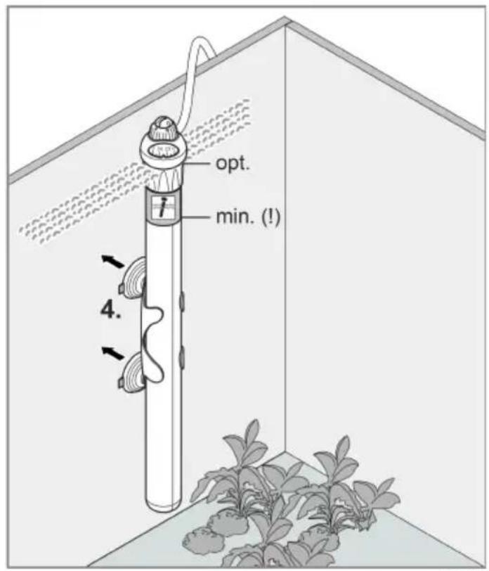
text_image
opt. min. (!) 4.HUP0005
VIGYÁZAT
text_image
Diagram illustrating a cable installation or power line with labeled components and water flow indicatorsHUP0002
text_image
Diagram showing a device with a rotary knob and dial, illustrating the process of rotation or adjustment.HU
HUP0006
text_image
Technical diagram of a vertical cylindrical device with labeled components and exploded view, showing internal components and wiring connections.HUP0001
text_image
Diagram illustrating a cable installation or power system with labeled components and water flow indicatorsHUP0002
PL
Kontrola temperatury
text_image
Diagram showing a device with a rotary knob and dial, illustrating the process of rotation or adjustment.HUP0006
| V | T | ||
| 5 °C | 10 °C | 15 °C | |
| ≤ 25 l | 25 W | 25 W | 75 W |
| ≤ 50 l | 50 W | 50 W | 100 W |
| ≤ 75 l | 50 W | 75 W | 150 W |
| ≤ 100 l | 75 W | 100 W | 200 W |
| ≤ 150 l | 100 W | 150 W | 300 W |
| ≤ 200 l | 150 W | 200 W | 2 ×200 W |
| ≤ 250 l | 200 W | 250 W | 2 × 250 W |
| ≤ 300 l | 250 W | 300 W | 2 × 300 W |
text_image
Technical diagram of a vertical cylindrical device with labeled components and exploded view, showing internal components and wiring connections.HUP0001
text_image
Diagram illustrating a mechanical or electrical component with labeled parts and directional arrows indicating motion or assembly.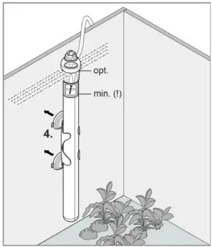
text_image
opt. min. (!) 4.CS
Uvedení do provozu
Zapnutí / vypnutí
POZOR
text_image
Diagram illustrating a cable installation or power line with labeled components and water flow indicatorsHUP0002
Kontrola hodnot teploty
text_image
Diagram showing a rotary switch mechanism with labeled degrees and a water level indicatorHUP0006
Čištění a údržba
CS
text_image
Technical diagram of a vertical cylindrical device with labeled components and exploded view, showing internal components and wiring connections.HUP0001
text_image
Diagram of a water pump or valve assembly with labeled components and directional arrows indicating flow or movement.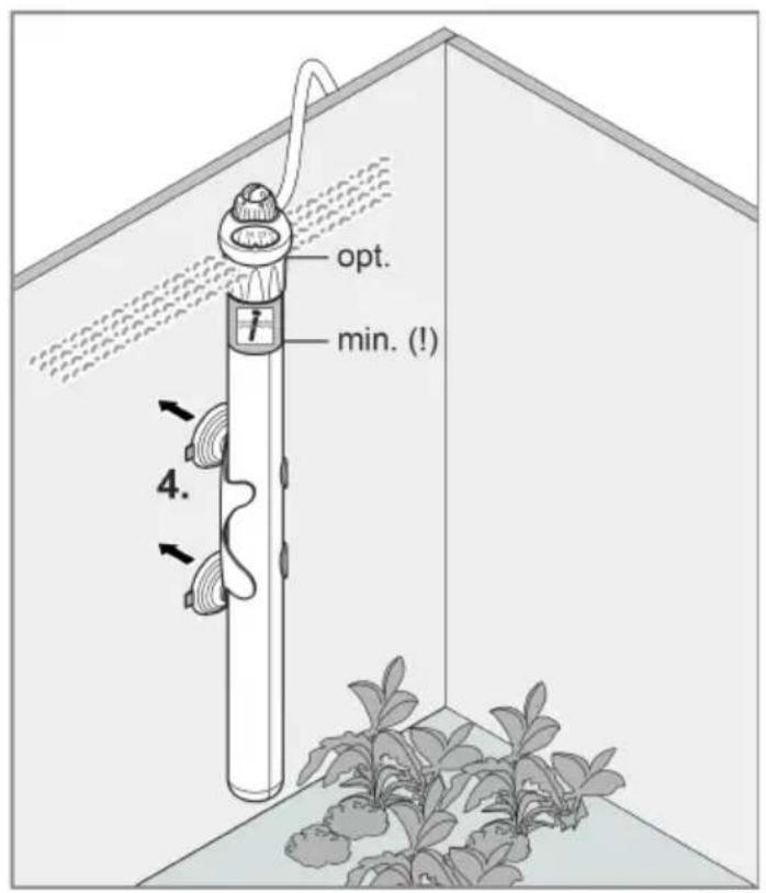
text_image
opt. min. (!) 4.HUP0005
text_image
Diagram illustrating a cable installation or power line with labeled components and water flow indicatorsHUP0002
text_image
Diagram showing a device with a rotary knob and dial, annotated with directional arrows and numerical values.HUP0006
Čistenie a údržba
text_image
Technical diagram of a vertical cylindrical device with labeled components and exploded view, showing internal components and wiring connections.HUP0001
| 1 | Grelna glava z regulatorjem temperature |
| 2 | Oznaka najmanjše globine potapljanja |
| 3 | Omrežni kabel |
| 4 | Stekleni bat z gretjem |
| 5 | Nosilec |
| 6 | Priseski |
Simboli na napravi


text_image
Diagram illustrating a mechanical or electrical component with labeled parts and directional arrows indicating motion or assembly.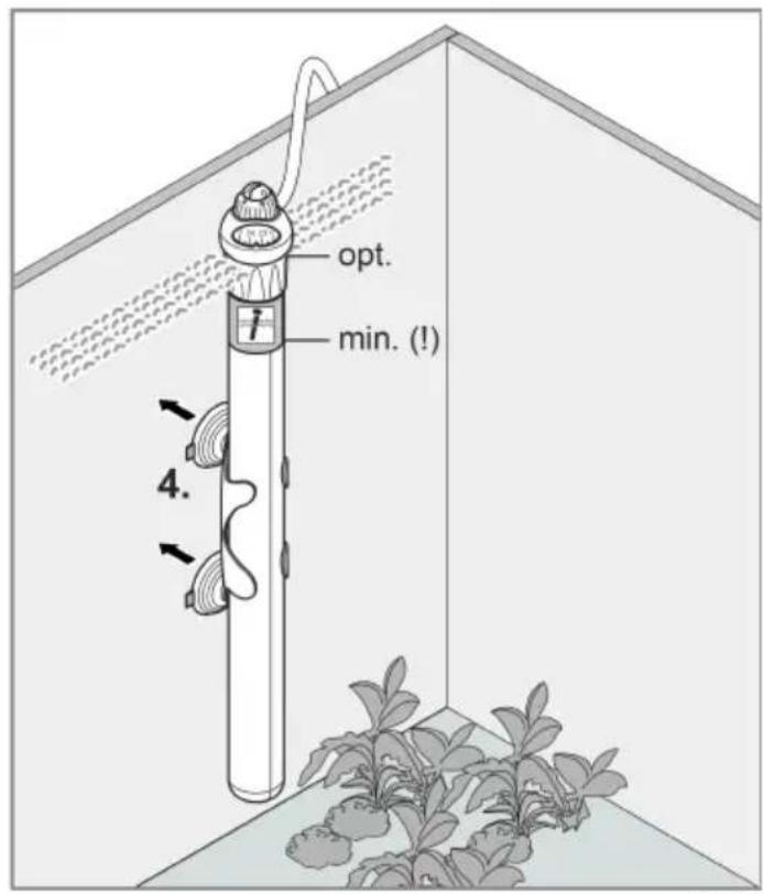
text_image
opt. min. (!) 4.SL
Zagon
Vklop / izklop
PREVIDNO
text_image
Diagram illustrating a cable installation or water flow system with labeled components and directional arrows indicating flow direction.HUP0002
Preverjanje vrednosti temperature
text_image
Diagram illustrating the working principle of a fuel injector with labeled parts and directional arrows indicating rotation.HUP0006
text_image
Technical diagram of a vertical cylindrical device with labeled components and exploded view, showing internal components and wiring connections.HUP0001
| 1 | Glava grijača s regulatorom temperature |
| 2 | Oznaka minimalne dubine uranjanja |
| 3 | Električni kabel |
| 4 | Stakleni stap s grijačem |
| 5 | Držač |
| 6 | Sisaljke |
Simboli na uređaju


text_image
Diagram illustrating a mechanical or electrical device with labeled components and directional arrows indicating motion or flow.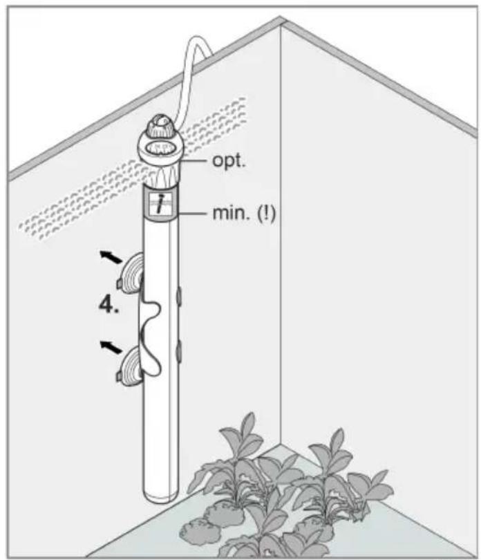
text_image
opt. min. (!) 4.HUP0005
OPREZ
text_image
Diagram illustrating a cable installation or water flow system with labeled components and directional arrows indicating flow direction.HUP0002
text_image
Diagram showing a device with a rotary knob and dial, illustrating the process of rotation or adjustment.HUP0006
| V | T | ||
| 5 °C | 10 °C | 15 °C | |
| ≤ 25 l | 25 W | 25 W | 75 W |
| ≤ 50 l | 50 W | 50 W | 100 W |
| ≤ 75 l | 50 W | 75 W | 150 W |
| ≤ 100 l | 75 W | 100 W | 200 W |
| ≤ 150 l | 100 W | 150 W | 300 W |
| ≤ 200 l | 150 W | 200 W | 2 ×200 W |
| ≤ 250 l | 200 W | 250 W | 2 × 250 W |
| ≤ 300 l | 250 W | 300 W | 2 × 300 W |
Potrošni dijelovi
- Sisaljke
Zbrinjavanje
NAPOMENA
text_image
Technical diagram of a vertical cylindrical device with labeled components and exploded view, showing internal components and wiring connections.HUP0001
text_image
Diagram of a mechanical device with labeled parts and directional arrows indicating motion or assembly.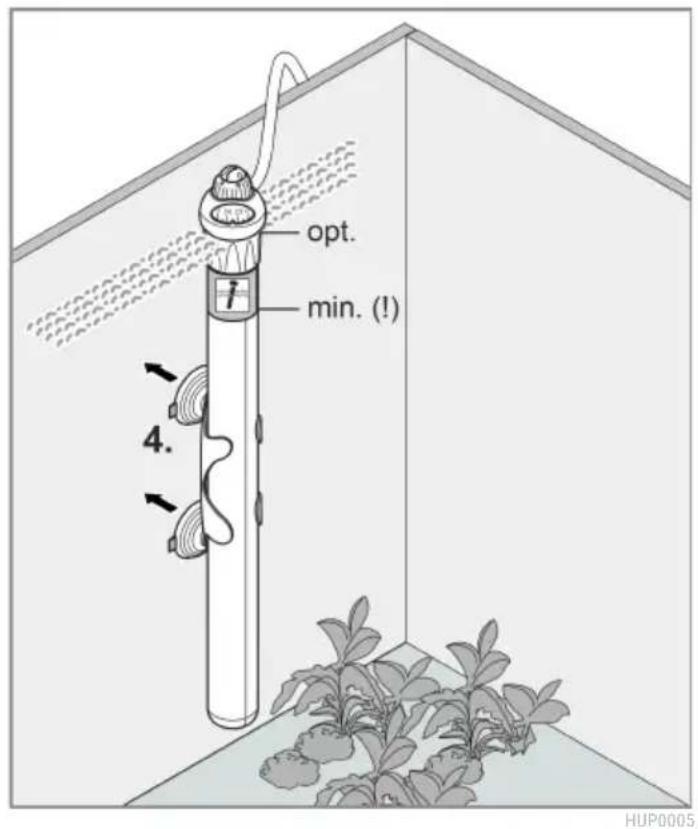
text_image
opt. min. (!) 4. HUP0005HUP0005
text_image
Diagram illustrating a water heating system with a power outlet, pipe, and valve, showing water flow and drop points.HUP0002
text_image
Diagram showing a device with a rotary knob and dial, annotated with directional arrows and numerical values.HUP0006
| V | T | ||
| 5 °C | 10 °C | 15 °C | |
| ≤ 25 l | 25 W | 25 W | 75 W |
| ≤ 50 l | 50 W | 50 W | 100 W |
| ≤ 75 l | 50 W | 75 W | 150 W |
| ≤ 100 l | 75 W | 100 W | 200 W |
| ≤ 150 l | 100 W | 150 W | 300 W |
| ≤ 200 l | 150 W | 200 W | 2 ×200 W |
| ≤ 250 l | 200 W | 250 W | 2 × 250 W |
| ≤ 300 l | 250 W | 300 W | 2 × 300 W |
Consumabile
- Ventuze
text_image
Technical diagram of a vertical cylindrical device with labeled components and exploded view, showing internal components and wiring connections.HUP0001
text_image
Diagram illustrating a mechanical or electrical component with labeled parts and directional arrows indicating motion or assembly.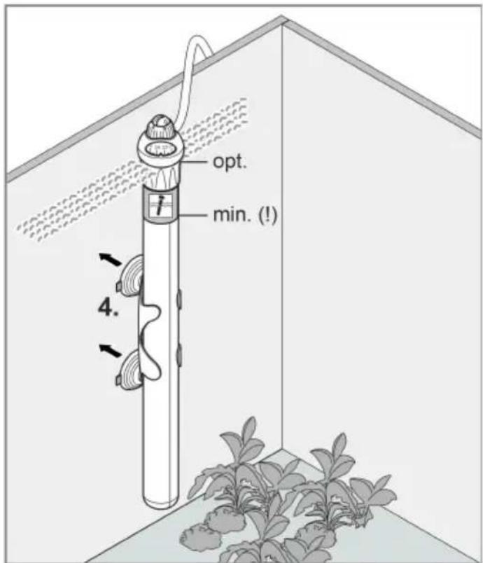
text_image
opt. min. (!) 4.HUP0005

ВНИМАНИЕ
text_image
Diagram illustrating a cable installation or power line with labeled components and water flow indicatorsHUP0002
text_image
Diagram showing a valve mechanism with numbered parts and directional arrows indicating rotation or movement.HUP0006
text_image
Technical diagram of a vertical cylindrical device with labeled components and exploded view, showing internal components and wiring connections.HUP0001
text_image
Diagram illustrating a mechanical or electrical component with labeled parts and directional arrows indicating motion or assembly.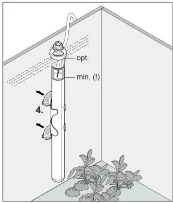
text_image
opt. min. (!) 4.HUP0005
UK

ОБЕРЕЖНО
text_image
Diagram illustrating a cable installation or power line with labeled components and water flow indicatorsHUP0002
text_image
Diagram illustrating the working principle of a fuel injector with labeled parts and directional arrows indicating rotation.HUP0006
Чистка і догляд
text_image
Technical diagram of a vertical tube with labeled components and internal parts, including numbered parts 1 through 6.HUP0001
text_image
Diagram illustrating a mechanical or electrical component with labeled parts and directional arrows indicating motion or assembly.
text_image
opt. min. (!) 4.HUP0005
ОСТОРОЖНО
text_image
Diagram illustrating the principle of a power plug installation, showing current flow and water displacement.HUP0002
text_image
Diagram illustrating the working principle of a micrometer, showing dial and pointer mechanism with numbered parts.HUP0006
Очистка и уход
text_image
Technical diagram of a cylindrical device with labeled components and exploded view, showing internal components and wiring connections.HUP0001
text_image
Diagram illustrating a water heating system with a power outlet, pipe, and water displacement indicatorsHUP0002
检查温度值
text_image
Diagram showing a rotary oil lamp mechanism with labeled parts and directional arrows indicating rotation or movement.HUP0006
清洁和保养
需要时用清水和软海绵或擦布清洁设备。
- 请勿使用清洁剂或化学溶液。
故障排除