
EHSXB04P30BA - Boiler DAIKIN - Free user manual and instructions
Find the device manual for free EHSXB04P30BA DAIKIN in PDF.

| Product type | Boiler (air-to-water heat pump with electric backup and solar integration) |
| Brand | Daikin |
| Model | EHSXB04P30BA |
| Dimensions (H x W x D) | 180 x 60 x 60 cm |
| Net weight | 106 kg |
| Power supply | 230 V single phase, 50 Hz |
| Nominal heating capacity (A7/W35) | 4.53 kW |
| Nominal COP (A7/W35) | 5.23 |
| Hot water tank capacity | 260 liters |
| Maximum water temperature | 85 °C (tank), 80 °C with backup |
| Heating operating range | 15 to 55 °C |
| Cooling operating range (X version) | 5 to 22 °C |
| Max operating pressure (heating) | 3 bar |
| Hydraulic connections | 1" male thread cold/hot water, 1" female thread heating |
| Refrigerant | R410A (quantity according to outdoor unit) |
| Main functions | Heating, DHW production, optional cooling, electric backup, solar integration |
| Periodic maintenance | Annual inspection by a professional, pressure check, bleeding, filter cleaning |
| Safety | Frost protection, safety valve, temperature limiter, emergency stop |
| Repairability | Original Daikin spare parts available, replacement possible by a professional |
| General information | Manual available in French, 730 pages, free download |
Frequently Asked Questions - EHSXB04P30BA DAIKIN
User questions about EHSXB04P30BA DAIKIN
0 question about this device. Answer the ones you know or ask your own.
Ask a new question about this device
Download the instructions for your Boiler in PDF format for free! Find your manual EHSXB04P30BA - DAIKIN and take your electronic device back in hand. On this page are published all the documents necessary for the use of your device. EHSXB04P30BA by DAIKIN.
USER MANUAL EHSXB04P30BA DAIKIN
Installation and operating instructions
Daikin Altherma integrated solar unit V5.2
Installation and operating instructions Daikin Altherma integrated solar unit
- 04P30B
- 08P30B
- 08P50B
- 16P50B
| CE - DECLARATION-OF-CONFORMITYCE - KONFORMITÄTSERKLÄRUNGCE - DECLARATION-DE-CONFORMITECE - CONFORMITEITSVERKLARING | CE - DECLARACION-DE-CONFORMIDADCE - DICHIARAZIONE-DI-CONFORMITACE - ΔΗΛΩΣΗ ΣΥΜΜΟΡΦΩΣΗΣ | CE - DECLARAÇÃO-DE-CONFORMIDADECE - ЗАЯВЛЕНИЕ-О-СООТВЕТСТВИICE - OVERENSSSTEMMELSESERKLÄRINGCE - FÖRSÄKRAN-OM-ÖVERENSTÄMMELSE | CE - ERKLÄERING OM-SAMSVARCE - ILMOITUS-YHĐENMUKAISUDESTACE - PROHLÄŞENİ-O-SHODË | CE - IZJAVA-O-USKLADENOSTICE - MEGFELELOSEĞI-NYILATKOZATCE - DEKLARACJA-ZGODNOŚCICE - DECLARAȚIE-DE-CONFORMITATE | CE - IZJAVA O SKLADNOSTICE - VASTAVUSDEKLARATSIOONCE - ДЕКЛАРАЦИЯ-ЗА-СЪОТВЕТСТВИЕ | CE - ATITIKTIES-DEKLARACIJACE - ATBILŠTİBAS-DEKLARĆCIJACE - VYHLÄSENIE-ZHODYCE - UYUMLULUK-BEYANI |
| Daikin Europe N.V. | ||||||
| 01 Ⓐ️ denotes under its sole responsibility that the equipment to which this declaration relales:02 Ⓓ️ erklärt auf seine alleingige Verantwortung daß die Ausrüstung für die diese Erklärung bestimmt ist:03 Ⓕ dédate sous sa seule responsabilité que l'équipement visé par la présente déclaration:04 ⒯ verkaat hierbij op eigen exclusive verantwoordelijkheid dat de apparatur waarop deze verklaring betrekking heeft:05 Ⓙ declara bajo su única responsabilidad que el equipo al que hace referencia la declaración:06 Ⓡ dichiara sotto la propria responsabilità che gli apparecchi a cui è riferita questa dichiarazione:07 Ⓔ δηλινει με αποκλοστηκή της ευθίνη οι ο έξοπλομός οτον οπροιο ανοφέταιο η παροίου δήλυση:08 ⒨ declara sob sua exclusiva responsabilicade que os equipamentos a que esta declaração se refere: | 09 Ⓔ️ заявляет, исключительно под свою ответственность, что оборудование, к которому относится настоящее заявление:10 Ⓔ erklærer under enansvarlig, at udstyret, som er omfattet af denne erklæring:11 Ⓗ deklarærer i egenskap av huvudansvarig, att ultrustningen som berörs av denna deklaration innebär att:12 ⒝ erklærer el fullstendig ansvar for at del utsýr som bereres av denne deklarasjon innebarrer at:13 Ⓘ ilmoitaa yksinomaan omalla vastuillaan, että támán ilmoituksen tarkoltamat laitteet:14 ⒰ prohlăsuje ve svă plnė odpovidnostli, že zařízeni, k němuž se toto prohlăšení vztahuje:15 Ⓙ iržavljuje pod isklůjčivo vlaslítom odgovornošću da oprema na koju se ova izjava odnosi:16 ⒯ teljes felelőssége tudátaban kijelenti, hogy a berendezések, melyekre e nylatkozat vonatkozik: | 17 ⒲ deklaruje na własną i wyłączną odpowiedzialność, że urządzenia, których la deklaracja dotyczy:18 ⒳ declară pe proprie răspundere că echipamentele la care se referă această declarație:19 Ⓔ zvo odgovornošto izjavlja, da je oprema naprav, na katero se izjava nanaša:20 Ⓗt kinnitab oma täielikul vastutusel, et käesleva deklaratsiooni alla kuuluv varustus:21 Ⓙ️ декларира на свсяя отговорност, че оборудването, за което се отнася тази декларация:22 ⒯ visiska savo atsakomyte skelbia, kad jranga, kuriai talkoma ši deklaracija:23 Ⓘ ar pilnu atbildibu apliecina, ka täläk aprakstilās iekārtas, uz kurām atiecas šī deklaracija:24 Ⓙv vyhlasuje na vlastnū zodpovednost, že zariadenie, na ktorė sa vztahuje toto vyhlásenie:25 Ⓙ tamamen kendi sorumluluğunda olmak üzere bu bildirinin Iğili olduğu donanimmin asağidaki gibi olduğunu beyan edier: | ||||
| EHSX04P30B, EHSXB04P30B, EHSH04P30B, EHSHB04P30B, EHSX08P30B, EHSXB08P30B, EHSH08P30B, EHSHB08P30B,EHSX08P50B, EHSXB08P50B, EHSH08P50B, EHSHB08P50B, EHSX16P50B, EHSXB16P50B, EHSH16P50B, EHSHB16P50B | ||||||
| 01 are in conformity with the following standard(s) or other normative document(s), provided that these are used in accordance with our instructions: | 08 estão em conformidade com a(s) seguinte(s) norma(s) ou outro(s) documento(s) normativo(s), desde que estes sejam utilizados de acordo com as nossas instruções: | 16 megfelenek az alábbi szabvány(ok)nak vagy egyéb irányadó dokumentum(ok)nak, ha azokat előirás szerint használják: |
| 02 der/den folgenden Nom(en) oder einem anderen Normdokument oder -dokumenten entspricht/entsprechen, unter der Voraussetzung, daß sie gemäß unseren Anweisungen eingesetzt werden: | 09 соответствуют следующим стандарам или другим нормативним документам, при условии их использования согласно нашим инструкциям: | 17 spelnajay wymogi następujących norm i innych dokumentów normalizacyjnych, pod warunkiem ze używane są zgodnie z naszymi instrukcijami: |
| 03 sont conformes à le/aux norme(s) ou autre(s) document(s) normatf(s), pour autant qu'ils soient utilisés conformément à nos instructions: | 10 overholder folgende standard(er) eller anöt/andre retningsgivende dokument(er), fonudsat at disse anvendes i henhold til vore instrukser: | 18 sunt in conformitate cu urmátonul (urmátocarele) standard(e) sau alt(e) document(e) normativ(e), cu conditja ca acestea så fie utilizate în conformitate cu instrucjuniile noastre: |
| 04 conform de volgende norm(en) of één of meer andere bindende documenten zijn, op voorwaarde dat ze worden gebruikt overeenkomstig onze instructies: | 11 respektive utrustning är utförd i överensstämmelse med och följer följande standard(er) eller andra normgivande dokument, under förutsättning att användning sker i överensstämmelse med våra instruktioner: | 19 skladni z naslednijmi standardi in drugimi normativi, pod pogojem, da se uporabljajo v skladu z našimi navodili: |
| 05 están en conformidad con la(s) siguiente(s) norma(s) u otro(s) documento(s) normativo(s), siempre que sean utilizados de acuerdo con nuestras instruziones: | 12 respektive utstyr er i overensstemmelse med falgende standard(er) eller andre normgivende dokument(er), under forutsetning av at disse brukes i henhold til våre instrukser: | 20 on vastavuses järgmis(te) standard(te)ga või teiste normativsete dokumentidega, kui neid kasutatakse vastavalt meie juhendtele: |
| 06 sono conformi ali(i) seguente(i) standard(s) o altro(i) documento(i) a carattere normativo, a patto che vengano usati in conformità alle nostre istruzioni: | 13 vastaavat seuraavien standardien ja muiden ohjeelisten dokumentien vaatimuksia edellyttäen, että nità käytetään ohjeidemme mukaisesti: | 21 съответствят на следните стандарти или други нормативни документи, при условие, че со изпопаат съгласко нашите инструкция: |
| 07 čivai cůjupuvva με το(α) ακόλουθο(α) πρότυμο(α) ή άλιο έγγραφο(α) κανονισμών, υπό την προϋπόθεση οπι χρησμοποιούντα σύμφυνα με τις οδήγιες μος: | 14 za předpokladu. že jsou využívány v souladu s našimi pokyny, odpovídají následujícim normám nebo normativnim dokumentüm: | 22 abtinka žemiau nurodytus standartus ir (arba) kitus norminius dokumentus su salgya, kad yra naudojami pagal müsų nurodymus: |
| 15 u skladu sa slijedećim standardom(ima) ili drugim normativnim dokumentom(ima), uz uvjet da se oni koriste u skladu s našim uputama: | 23 tad, ja lietoti albilstoši ražotăja norădijumiem, albist sekojišiem standartiem un citem normativiem dokumentiem: | |
| 24 sú v zhode s nasledovnou(ými) normou(ami) alebo iným(i) normativnym(i) dokumentom(ami), za predpokladu, že sa používaju v sülade s našim návodom: | ||
| 25 ürünün, talimatlanmza göre kullanılması koşuluyla asajideki standardar ve norm belirten belgelefe uyumludur: |
EN60335-2-40,
EN55014-1: 2006 (+A1: 2009 +A2: 2011),
EN55014-2: 1997 (+A1: 2001 +A2: 2008),
EN61000-3-2: 2014,
EN61000-3-3: 2013,
EN61000-6-2: 2007 (+A1: 2011),
| 01 following the provisions of: | 10 under iagttagelse af bestemmelserne i: | 19 ob upoštevanju dolob: | Low Voltage 2014/35/EUElectromagnetic Compatibility 2014/30/EU | 01 Directives, as amended. | 10 Direktiver, med senere ændringer. | 19 Direktive z vsemi spremembami. |
| 02 gemäß den Vorschriften der: | 11 enligt villkoren i: | 20 vastavall nõutele: | 02 Direktiven, gemäß Änderung. | 11 Direktiv, med företagna ændringar. | 20 Direktivid koos muudatustega. | |
| 03 conformément aux stipulations des: | 12 gilt i henhold til bestammelsene i: | 21 спедвайки клaysите на: | 03 Directives, telles que modifiées. | 12 Direktiver, med forelatte endringer. | 21 Direktivien, с техните изменения. | |
| 04 overeenkomstig de bepalingen van: | 13 noudattaen määräyksiä: | 22 laikantis nuostatu, pateikiamı: | 04 Richtlijnen, zoals geamendeerd. | 13 Direktivjek, sellasina kuin ne oval muulettuina. | 22 Direktivose su papildymais. | |
| 05 siguiendo las disposiciones de: | 14 za dodrženi ustanoveni předpisu: | 23 ievěrojor prasības, kas noteiktas: | 05 Directivas, según lo emmendado. | 14 v platném znění. | 23 Direktivas un to papildnájumos. | |
| 06 secondo le prescrizioni per: | 15 prema odredbama: | 24 održavajúc ustanovenia: | 06 Direttive, come da modifica. | 15 Smjemice, kako je izmjenjeno. | 24 Smermice, v platnom znení. | |
| 07 με τήρηση των διατόζευν των: | 16 követi a(z): | 25 bunun kopullarina uygun olarak: | 07 Obrzykiv, ömuç čyouv spormonirjści. | 16 irányelv(ek) és módosításak randelkazéseit. | 25 Değişirilmiş halleriyle Yönetmelikler. | |
| 08 de acordo com o previsto em: | 17 zgodnie z postanowieniami Dyrektyw: | 08 Directivas, conforme alteração em. | 17 z późniejszymi poprawkami. | |||
| 09 в соответствии с положениями: | 18 în urma prevederilor: | 09 Direktiva co всеми поправками. | 18 Directivelor, cu amendamentele respective. |

Shigeki Morita
Director
Ostend, 20th of April 2016
DAIKIN EUROPE N.V.
- 04P30B
- 08P30B
- 08P50B
- 16P50B
EHS(X/H)...04P30B/08PxxB:
Cu ∅ 6,4 mm (1/4"),
Daikin Altherma EHS(X/H)...16P50B:
Cu ∅ 9,5 mm (3/8")
t_DHW1, t_DHW2
4.1.2 Daikin Altherma EHS(X/H)...P50B

natural_image
Technical line drawing of an electrical enclosure with labeled components (no text or symbols present)natural_image
Technical line drawing of a mechanical assembly with labeled parts A and B (no text or symbols beyond labels)flowchart
graph TD
    A["A1P"] --> B["X1A"]
    A --> C["X20A"]
    A --> D["X30A"]
    A --> E["X40A"]
    A --> F["X50A"]
    A --> G["X60A"]
    A --> H["X70A"]
    A --> I["X80A"]
    A --> J["X90A"]
    A --> K["X10A"]
    A --> L["X11A"]
    A --> M["X12A"]
    A --> N["X13A"]
    A --> O["X14A"]
    A --> P["X15A"]
    A --> Q["X16A"]
    A --> R["X17A"]
    A --> S["X18A"]
    A --> T["X19A"]
    A --> U["X20A"]
    A --> V["X21A"]
    A --> W["X22A"]
    A --> X["X23A"]
    A --> Y["X24A"]
    A --> Z["X25A"]
    A --> AA["X26A"]
    A --> AB["X27A"]
    A --> AC["X28A"]
    A --> AD["X29A"]
    A --> AE["X30A"]
    A --> AF["X31A"]
    A --> AG["X32A"]
    A --> AH["X33A"]
    A --> AI["X34A"]
    A --> AJ["X35A"]
    A --> AK["X36A"]
    A --> AL["X37A"]
    A --> AM["X38A"]
    A --> AN["X39A"]
    A --> AO["X40A"]
    A --> AP["X41A"]
    A --> AQ["X42A"]
    A --> AR["X43A"]
    A --> AS["X44A"]
    A --> AT["X45A"]
    A --> AU["X46A"]
    A --> AV["X47A"]
    A --> AW["X48A"]
    A --> AX["X49A"]
    A --> AY["X50A"]
    A --> AZ["X51A"]
    A --> BA["X52A"]
    A --> BB["X53A"]
    A --> BC["X54A"]
    A --> BD["X55A"]
    A --> BE["X56A"]
    A --> BF["X57A"]
    A --> BG["X58A"]
    A --> BH["X59A"]
    A --> BI["X60A"]
    A --> BJ["X61A"]
    A --> BK["X62A"]
    A --> BL["X63A"]
    A --> BM["X64A"]
    A --> BN["X65A"]
    A --> BO["X66A"]
    A --> BP["X67A"]
    A --> BQ["X68A"]
    A --> BR["X69A"]
    A --> BS["X70A"]
    A --> BT["X71A"]
    A --> BU["X72A"]
    A --> BV["X73A"]
    A --> BW["X74A"]
    A --> BX["X75A"]
    A --> BY["X76A"]
    A --> BZ["X77A"]
    A --> CA["X78A"]
    A --> CB["X79A"]
    A --> CC["X80A"]
    A --> CD["X81A"]
    A --> CE["X82A"]
    A --> CF["X83A"]
    A --> CG["X84A"]
    A --> CH["X85A"]
    A --> CI["X86A"]
    A --> CJ["X87A"]
    A --> CK["X88A"]
    A --> CL["X89A"]
    A --> CM["X90A"]
    A --> CN["X91A"]
    A --> CO["X92A"]
    A --> CP["X93A"]
    A --> CQ["X94A"]
    A --> CR["X95A"]
    A --> CS["X96A"]
    A --> CT["X97A"]
    A --> CU["X98A"]
    A --> CV["X99A"]
    A --> CW["X100A"]
natural_image
Technical line drawing of a mechanical assembly with no visible text or symbolsnatural_image
Technical diagram of a mechanical assembly with arrows indicating motion or force direction (no text or symbols present)natural_image
Technical line drawing of a mechanical assembly with wires and components (no text or symbols)natural_image
Technical line drawing of a mechanical assembly with wires and components (no text or symbols)natural_image
Technical line drawing of a mechanical assembly with no visible text or symbolsnatural_image
Technical line drawing of a mechanical assembly with pipes and housing (no text or symbols)
line
| p / bar | U / V | | ------- | ----- | | 0.5 | 0.0 | | 1.0 | 0.5 | | 1.5 | 1.0 | | 2.0 | 1.5 | | 2.5 | 2.0 | | 3.0 | 2.5 | | 3.5 | 3.0 | | 4.0 | 3.5 | | 4.5 | 4.0 |Backup-Heater 9, 14, 23, 25, 42, 44, 52
Anschlüsse 9, 16, 17
Installation 21
Wichtige Hinweise 7
|
Inbetriebnahme 41
Estrichfunktion 43
Regelung 41
K
Installation and operating instructions
Daikin Altherma integrated solar unit V5.2
Installation and operating instructions Daikin Altherma integrated solar unit
English
Daikin
Altherma
EHS(X/H)(B)
- 04P30B
- 08P30B
- 08P50B
- 16P50B
1 General Information.... 3
1.1 Observing instructions .... 3
2 Safety 4
2.1 Warning signs and explanation of symbols .... 4
2.1.1 Meaning of the warnings....4
2.1.2 Validity....4
2.1.3 Handling instructions....4
2.2 Avoiding danger 5
2.3 Intended use 5
2.4 Instructions for operating safety ..... 5
2.4.1 Before working on the hydraulic system .....5
2.4.2 Electrical installation 6
2.4.3 Working on cooling systems (heat pump)....6
2.4.4 Site of installation 6
2.4.5 Requirements for the heating and storage water . .7
2.4.6 Heating system and sanitary connection .....7
2.4.7 Operation 8
2.4.8 Instruct the operator .....8
3 Product description....9
3.1 Design and components 9
3.1.1 Top of unit .....9
3.1.2 Device housing and internal design Daikin Altherma EHS(X/H)...P30B .....10
3.1.3 Device housing and internal design Daikin Altherma EHS(X/H)B ...P30B .....11
3.1.4 Device housing and internal design Daikin Altherma EHS(X/H)...P30B .....12
3.1.5 Device housing and internal design Daikin Altherma EHS(X/H) B...P50B .....13
4 Set-up and installation 15
4.1 Dimensions and connections ..... 16
4.1.1 Daikin Altherma EHS(X/H)...P30B .....16
4.1.2 Daikin Altherma EHS(X/H)...P50B .....17
4.1.3 Scope of delivery....18
4.2 Set-up 18
4.3 Remove cover hood and heat insulation ..... 20
4.4 Water connection 21
4.4.1 Aligning the connections of the heating feed and return flow .....22
4.4.2 Connecting hydraulic lines .....23
4.4.3 Assembly DB connection kit .....24
4.4.4 Assembly Biv connection kit .....24
4.5 Electrical connection 25
4.5.1 Overall connection plan Daikin Altherma EHS(X/H) .....26
4.5.2 Position of the circuit boards.....27
4.5.3 Connection assignment, circuit board A1P .....27
4.5.4 Terminal assignment for the RTX-EHS circuit board .....27
4.5.5 Connection assignment, circuit board RoCon BM1.....28
4.5.6 Mains connection Daikin Altherma EHS(X/H)....28
4.5.7 Open controller housing and making the electrical connections....29
4.5.8 Connection of ERLQ exterior heat pump unit . . . .29
4.5.9 Connection of external temperature sensor RoCon OT1....29
4.5.10 Connection of an external switching contact....30
4.5.11 External demand signal (EDS) .....30
4.5.12 Connection of the electrical Daikin Backup-Heater (EKBUxx) .....31
4.5.13 Connection of an external heat generator.....32
4.5.14 Connection of the Daikin room thermostat .....33
4.5.15 Connection optional RoCon system components .34
4.5.16 Connection of the Daikin FWXV(15/20)AVEB...34
4.5.17 Connection switch contacts (AUX outputs) ..... 35
4.5.18 Low tariff mains connection (HT/NT)....35
4.5.19 Connection intelligent controller (Smart Grid - SG) 36
4.5.20 Symbols and legend keys on connection and circuit diagrams 36
4.6 Laying coolant lines. 39
4.7 Pressure test and filling the coolant circuit . . . 39
4.8 Filling the system with water 39
4.8.1 Checking the water quality and adjusting the pressure gauge 39
4.8.2 Filling the hot water heat exchanger 40
4.8.3 Filling the storage tank 40
4.8.4 Filling the heating system 40
5 Start-up. 41
5.1 Initial start-up.... 41
5.1.1 Requirements 41
5.1.2 Start-up 41
5.1.3 Set the commissioning parameters ..... 42
5.1.4 Venting the hydraulics 42
5.1.5 Check the minimum flow rate 43
5.1.6 Configuring Screed Program parameters (only if necessary) 43
5.2 Re-commissioning.... 44
5.2.1 Requirements 44
5.2.2 Start-up 44
6 Decommissioning 45
6.1 Temporary shutdown 45
6.1.1 Draining the storage tank 45
6.1.2 Draining the heating circuit and hot water circuit. 46
6.2 Final shutdown 47
7 Service and maintenance 49
7.1 General 49
7.2 Activities to be performed annually ..... 50
7.3 Filling and topping up the storage tank ..... 52
7.4 Filling and topping up the heating system....53
8 Errors, malfunctions and messages .... 55
8.1 Recognising errors, correcting malfunctions . . 55
8.1.1 Current fault display.... 55
8.1.2 Read Protocol 55
8.1.3 Troubleshooting.... 55
8.2 Malfunctions 56
8.3 Fault codes 59
8.4 Monitoring and configuration DIP Switch .... 66
8.5 Emergency operation 66
9 Hydraulic system connection.... 67
10 Technical data 70
10.1 Equipment data 70
10.1.1 Daikin Altherma EHS(X/H)...P30B ..... 70
10.1.2 Daikin Altherma EHS(X/H)...P50B ..... 73
10.2 Characteristic lines ..... 75
10.2.1 Sensor characteristic lines....75
10.2.2 Characteristic curves for pumps ..... 77
10.3 Tightening torque 77
10.4 Circuit diagram Daikin Altherma EHS(X/H)....78
11 Notes. 79
12 List of keywords 80
1 General Information
1.1 Observing instructions
Original Operating Instructions
These instructions are a >> translation of the original version << in your language.
Please read this manual carefully and thoroughly before proceeding with the installation or modification of the heating system.
Target Group
These instructions are aimed at people who are authorised and who have successfully completed a qualifying technical or skilled manual training program for the particular work to be carried out and who have participated in professional development seminars recognised by the appropriate responsible authority. This, in particular, includes heating specialists and climate control technicians who have experience, as a result of their technical training and their knowledge of the subject, of proper and appropriate installation and maintenance of heating, climate control and cooling installations and heat pumps.
This manual provides all the necessary information for installation, start-up and maintenance, as well as basic information on operation and settings. All parameters needed for trouble-free operation have been configured at the factory. Please see the attached documents for a detailed description of operation and control.
Relevant documents
– Daikin Altherma EHS(X/H):
- Operating instructions for the user/owner
– Commissioning checklist
- Operating instructions for the RoCon HP control unit
– External unit for Daikin Altherma EHS(X/H); the associated installation and operating instructions.
- When connecting to a solar system; the associated installation and operating instructions.
- If a Daikin FWXV(15/20)AVEB is connected; the associated installation and operating instructions.
- If a different heater or optional accessories are connected; the associated installation and operating instructions.
The guides are included in the scope of supply for the individual units.
2 Safety
2.1 Warning signs and explanation of symbols
2.1.1 Meaning of the warnings
Warnings in this manual are classified according into their severity and probability of occurrence.

DANGER!
Draws attention to imminent danger.
Disregarding this warning can lead to serious injury or death.

WARNING!
Indicates a potentially dangerous situation.
Disregarding this warning may result in serious physical injury or death.

CAUTION!
Indicates a situation which may cause possible damage.
Disregarding this warning may cause damage to property and the environment.

This symbol identifies user tips and particularly useful information, but not warnings or hazards.
Special warning signs
Some types of danger are represented by special symbols:

Electric current

Risk of burning or scalding

Risk of environmental damage

Danger of local freezing up

Health impairing or irritant materials

Prescribed temperature for continuous use

Danger of explosion
2.1.2 Validity
Some information in this manual has limited validity. The validity is highlighted by a symbol.

Heat pump exterior unit ERLQ

Heat pump interior unit EHS(X/H)

FWXV(15/20)AVEB

Only valid for Daikin Altherma EHS(X/H) with cooling function (see also section 2.3)

Pay attention to the stipulated tightening torque (See section 10.3 "Tightening torque")

Only applicable for the unpressurised solar system (drain-back)

Only applicable for the pressurised solar system.
2.1.3 Handling instructions
- Handling instructions are shown as a list. Actions of which the sequential order must be maintained are numbered.
→ Results of actions are identified with an arrow.
Entry into a setting procedure
- Exit from a setting procedure
2.2 Avoiding danger
The Daikin Altherma EHS(X/H) is state-of-the-art and is built to meet all recognised technical requirements. However, improper use may result in serious physical injuries or death, as well as property damage.
To prevent such risks, install and operate Daikin Altherma EHS(X/H) only:
– as stipulated and in perfect condition,
– with an awareness of safety and the hazards involved.
This assumes knowledge and use of the contents of this manual, of the relevant accident prevention regulations as well as the recognised safety-related and occupational health rules.

WARNING!
This equipment must only be used by children aged 8 and above and by persons with restricted physical, sensory or mental capabilities or with a lack of experience and knowledge, if they are under supervision or if they have been instructed in the safe use of the equipment and understand the dangers arising therefrom. Children must not play with the equipment. Cleaning or user maintenance must not be carried out by children without supervision.
2.3 Intended use
The Daikin Altherma EHS(X/H) may only be used for preparation of hot water, as a room heating system, and depending on its design, as a room cooling system.
The Daikin Altherma EHS(X/H) must be installed, connected and operated only according to the indications in this manual.
Only use of a suitable external unit approved by Daikin is permitted. The following combinations are permissible in this respect:
| Internal unit External unit | ||
| Heating and cooling (X) [IMAGE] | Heating only (H) | |
| EHSX04P30BEHSH04P30B | ERLQ004CAV3 | |
| EHSXB04P30BEHSHB04P30B | ||
| EHSX08P30BEHSH08P30B | ERLQ006CAV3ERLQ008CAV3 | |
| EHSXB08P30BEHSHB08P30B | ||
| EHSX08P50BEHSH08P50B | ||
| EHSXB08P50BEHSHB08P50B | ||
| EHSX16P50BEHSH16P50BERLQ011CA(V3/W1)* | ||
| EHSXB16P50BEHSHB16P50B | ERLQ014CA(V3/W1)*ERLQ016CA(V3/W1)* | |
XB / HB - Additional heat exchanger for the bivalent connection
* Not all the equipment mentioned here is offered in some countries because of the various different country-specific connection conditions.
Tab. 2-1 Permissible combinations of Daikin Altherma EHS(X/H) internal units and Daikin heat pump external units
Any other use outside the intended use is considered as improper. The operator alone shall bear responsibility for any resulting damage.
Intended use also includes compliance with the maintenance and service conditions.
Replacement parts must at least satisfy the technical requirements defined by the manufacturer.
This is the case, for example, with original spare parts.
2.4 Instructions for operating safety
2.4.1 Before working on the hydraulic system
- Work on the Altherma EHS(X/H) (such as setup, servicing, connection and initial start-up) is only to be carried out by persons who are authorised and who have successfully completed qualifying technical or vocational training and who have taken part in advanced training sessions recognised by the appropriate responsible authorities for the specific activity. This, in particular, includes heating specialists and climate control technicians who have experience, as a result of their technical training and their knowledge of the subject, of proper and appropriate installation and maintenance of heating, climate control and cooling installations and heat pumps.
- Switch off the external main switch before starting any work on the Daikin Altherma EHS(X/H) and secure it against unintentional switch-on.
- Lead tamper-proof seals must not be damaged or removed.
2 Safety
- Make sure that the safety valves comply with the requirements of EN 12828 when connecting on the heating side, and with the requirements of EN 12897 when connecting on the domestic water side.
- Only original Daikin replacement parts may be used.
- When working on the hydraulics, you must first drain the water or release the pressure using the internal KFE valve. Otherwise hot water can jet out under pressure and result in injury.
2.4.2 Electrical installation
- Electrical installation may be carried out only by electrical engineers and in compliance with the valid electro-technical guidelines as well as the regulations of the relevant energy supply company (EVU).
- Compare the mains voltage (\~230 V, 50 Hz or \~400 V, 50 Hz) indicated on the type plate with the supply voltage before connecting to the mains.
- Before beginning work on live parts, disconnect all of the systems circuits from the power supply (switch off main switch, disconnect fuse) and secure against unintentional restart.
- Equipment covers and service panels must be replaced as soon as the work is completed.
2.4.3 Working on cooling systems (heat pump)
The Daikin Altherma EHS(X/H) requires fluorinated greenhouse gas for its function.
i
For work on stationary refrigeration systems (heat pumps) and air conditioning systems, proof of expertise is required in the European Community according to the F-Gases Directive (EC) No. 303/2008.
– up to 3 kg coolant fill quantity: Expert certificate category II
- 3 kg coolant fill quantity or over: Expert certificate category I
- Always wear safety goggles and protective gloves.
- When working on the refrigerant circuit, ensure that the workplace is well ventilated.
- Never carry out work on the refrigerant circuit in closed rooms or work pits.
- Do not let coolant come into contact with open fire, embers or hot objects.
- Never allow coolant to escape into the atmosphere (high pressure at the point of the leak).
- When removing the service pipes from the filling connections, never hold the connections in the direction of your body. Residual refrigerant could escape.
- Components and spare parts must at least satisfy the technical requirements defined by the manufacturer.
2.4.4 Site of installation
For safe and fault-free operation, it is necessary that the installation location of the Daikin Altherma EHS(X/H) fulfils certain criteria.
Related information can be found in chapter 4.2.
Information on the installation site of other components can be found in the associated documentation supplied with them.
2.4.5 Requirements for the heating and storage water
Damage due to deposits and corrosion: observe the current technological regulations to prevent corrosion products and deposits.
Minimum requirements regarding the quality of filling and top-up water:
- Water hardness (calcium and magnesium, calculated as calcium carbonate): ≤3 mmol/l
• Conductivity: ≤1500 (ideal 100) S/cm - Chloride: ≤250 mg/l
- Sulphate: ≤ 250 mg/l
- pH value: 6,5 - 8,5
Measures for desalination, softening or hardness stabilisation are necessary if the filling and top-up water have a high total hardness (>3 mmol/l – total of the calcium and magnesium concentrations, calculated as calcium carbonate). We recommend the use of Fernox KSK limescale and corrosion protector. For other properties deviating from the minimum requirements, suitable conditioning measures are necessary to maintain the required water quality.
Using filling water and top-up water which does not meet the stated quality requirements can cause a considerably reduced service life of the equipment. The responsibility for this lies solely with the operator.
i
If an optional external heat generator is connected, these minimum requirements also apply to the filling and supplementary water for this heating circuit.
2.4.6 Heating system and sanitary connection
- Create a heating system according to the safety requirements of EN 12828.
- The plumbing connection must comply with the requirements of EN 12897. The requirements of the following must also be observed:
- EN 1717 – Protection against pollution of potable water installations and general requirements of devices to prevent pollution by backflow
- EN 61770 – Electric appliances connected to the water mains – Avoidance of back-siphonage and failure of hose-sets
- EN 806 – Specifications for installations inside buildings conveying water for human consumption
– and, in addition, the country-specific legislation.
During operation of the indoor unit with an auxiliary heat source, the storage tank temperature may exceed 65 °C, above all when solar energy is used.
- For this reason, some form of scalding protection needs to be included when you install the system (hot water mixing device, e.g. VTA32).
i
The domestic water quality must comply with the EU Guideline 98/83 EC and the regionally-applicable regulations.
If the indoor unit is connected to a heating system with steel pipes, radiators or non-diffusion-proof floor heating pipes, sludge and chips can enter the hot water storage tank and cause blockages, local overheating or corrosion damage.
- To prevent possible damage, install a dirt filter or sludge separator into the heating return flow of the system (SAS 1 or SAS 2).
- The dirt filter must be cleaned at regular intervals.
2.4.7 Operation
The Daikin Altherma EHS(X/H):
- Do not operate until all installation and connection work is completed.
- Only operate with a completely full storage tank (Level indicator) and heating circuit.
- Operate at a maximum pressure of 3 bar.
- Only connect with a pressure reducer on the external water supply (supply line).
- Only operate the with the specified quantity of coolant and the type of coolant specified.
- Only operate if the protective cover is installed.
The prescribed maintenance intervals must be maintained and the inspection work must be carried out.
2.4.8 Instruct the operator
- Before you hand over the Daikin Altherma EHS(X/H), explain to the user/owner how to operate and check the system.
- Hand over the technical documentation (this document and all supporting documents) to the user and advise him that these documents must be made available at all times and be stored in the immediate vicinity of the unit.
3 Product description
3.1 Design and components
3.1.1 Top of unit
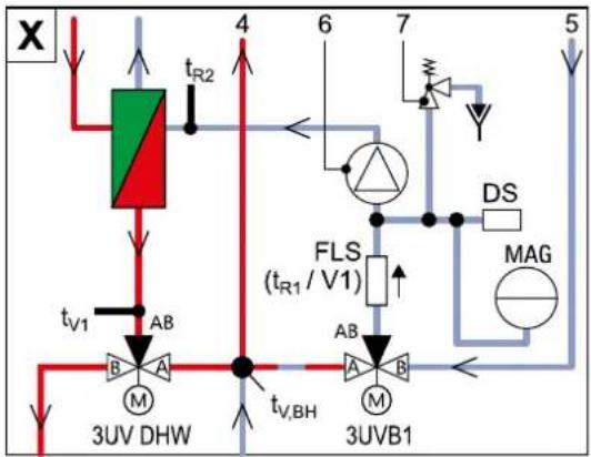
1 Solar=0 flow (1" IG)
2 Cold water flow (1" AG)
3 Hot water flow (1" AG)
4 Heating flow (1" AG)*
5 Heating return (1" AG)*
6 Circulation pump
7 Safety-pressure relief valve (heating circuit)
8 Automatic vent
17 Fill level indicator (tank water)
18 Connection for electrical Backup-Heater EKBUxx (R 1½" IG) (Accessory)
30 Plate heat exchanger (PWT)
31 Connection coolant fluid line
Daikin Altherma EHS(X/H)(B)04P30B/08PxxB: Cu ∅ 6,4 mm (1/4"),
Daikin Altherma EHS(X/H)(B)16P50B: Cu ∅ 9.5 mm (3/8")
32 Connection to coolant gas line
Cu ∅ 15,9 mm (5/8")
34 Ball cock (heating circuit)*
35 Combined filling and draining valve (heating circuit)
37 Storage tank temperature sensor t_DHW1 and t_DHW2
38 Connection diaphragm expansion vessel
39 Controller housing with elect. terminal strip
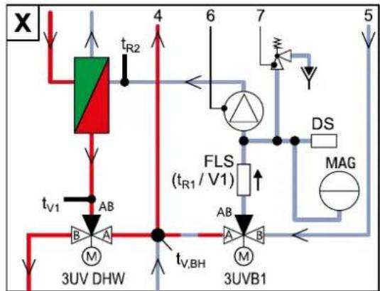
3UVB1
3-way diverter valve (internal heat generator circuit)
3UV DHW
3-way diverter valve (hot water / heating)
DS Pressure sensor
FLS (t_R1 / V1)
Return flow temperature and flow sensor
t_B2
Return flow temperature sensor
t_V1
Inflow temperature sensor
t_V,BH
Flow temperature sensor Backup-Heater

Safety devices
Observe tightening torque!
AG Male thread
IG Female thread
* Ball cock (1" IG) is supplied with the equipment
Fig. 3-1 Structure and components Daikin Altherma EHS(X/H) (top of unit)
3.1.2 Device housing and internal design Daikin Altherma EHS(X/H)...P30B
flowchart
graph TD
    A["3UV DHW"] -->|t_V1| B["Green Valve"]
    B --> C["4"]
    C --> D["6"]
    D --> E["7"]
    E --> F["5"]
    G["3UVB1"] --> H["AB"]
    H --> I["3UV DHW"]
    J["FLS (t_R1 / V1)"] --> K["AB"]
    K --> L["3UV DHW"]
    M["DS"] --> N["MAG"]
    O["t_V,BH"] --> P["A"]
    Q["t_R2"] --> R["B"]
    S["t_V1"] --> T["B"]
    U["t_V,BH"] --> V["A"]
Fig. 3-2 Structure and constituents Daikin Altherma EHS(X/H) ...P30B (External appearance and internal structure) Designations of key see tab. 3-1
3.1.3 Device housing and internal design Daikin Altherma EHS(X/H)B ...P30B
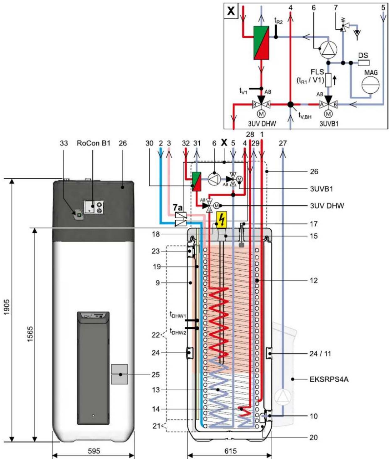
Fig. 3-3 Structure and constituents Daikin Altherma EHS(X/H) B ...P30B (External appearance and internal structure) Designations of key see tab. 3-1
3.1.4 Device housing and internal design Daikin Altherma EHS(X/H)...P30B
flowchart
graph TD
    A["3UV DHW"] -->|t_V1| B["3UVB1"]
    B -->|t_V,BH| C["3UV DHW"]
    C -->|AB| D["3UV DHW"]
    D -->|t_R2| E["4"]
    E -->|6| F["7"]
    F --> G["DS"]
    G --> H["MAG"]
    H --> I["3UV DHW"]
    style A fill:#f9f,stroke:#333
    style B fill:#ccf,stroke:#333
    style C fill:#cfc,stroke:#333
    style D fill:#fcc,stroke:#333
    style E fill:#cff,stroke:#333
    style F fill:#ffc,stroke:#333
    style G fill:#fcc,stroke:#333
    style H fill:#ffc,stroke:#333
    style I fill:#fcc,stroke:#333
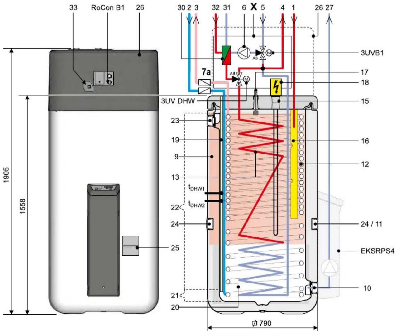
Fig. 3-4 Structure and constituents Daikin Altherma EHS(X/H) ...P50B (External appearance and internal structure) Designations of key see tab. 3-1
3.1.5 Device housing and internal design Daikin Altherma EHS(X/H) B...P50B
flowchart
graph TD
    A["3UV DHW"] -->|t_V1| B["Green Box"]
    B -->|t_R2| C["Red Box"]
    C --> D["3UVB1"]
    D --> E["3UV DHW"]
    E --> F["3UVB1"]
    F --> G["FLS (t_R1 / V1)"]
    G --> H["DS"]
    H --> I["MAG"]
    I --> J["7"]
    J --> K["Diode"]
    K --> L["4"]
    L --> M["6"]
    M --> N["5"]
    N --> O["7"]
    O --> P["7"]
    P --> Q["7"]
    Q --> R["7"]
    R --> S["7"]
    S --> T["7"]
    T --> U["7"]
    U --> V["7"]
    V --> W["7"]
    W --> X["7"]
    X --> Y["7"]
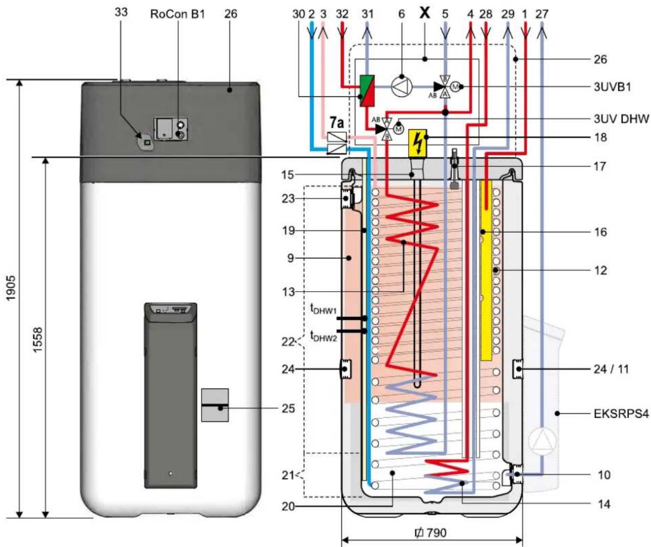
Fig. 3-5 Structure and constituents Daikin Altherma EHS(X/H) B ...P50B (External appearance and internal structure) Designations of key see tab. 3-1
3 Product description
1 Solar flow or connection for additional heat source(1" IG)
2 Cold water flow (1" AG)
3 Hot water flow (1" AG)
4 Heating flow (1" AG)*
5 Heating return (1" AG)*
6 Circulation pump
7a Recommended accessories: non-return valves (2 pcs.)
9 Storage tank (double walled jacket made of polypropylene with PUR hard foam heat insulation)
10 Filling and drainage connection or p=0 Solar - return flow connection
11 Mount for solar controller or handle
12 Heat exchanger (stainless steel) for drinking water heating
13 Heat exchanger (stainless steel) for storage tank charging or heating support
14 Heat exchanger (stainless steel) for pressurised solar storage tank charging
15 Connection for optional electrical Backup-Heater EKBUxx (R 1½" IG)
16 Solar inflow layering pipe
17 Fill level indicator (tank water)
18 Optional: Electrical Backup-Heater (EKBUxx)
19 Submersible sensor sleeve for storage tank temperature sensor t_DHW1 and t_DHW2
20 Unpressurised storage tank water
21 Solar zone
22 Hot water zone
23 Safety overflow connection
24 Mount for handle
25 Type plate
26 Protective cover
27 Solar - return
28 Solar - feed (3/4" IG + 1" AG)
Daikin Altherma EHS(X/H) B
(only Typ ... Biv)
29 Solar - return (3/4" IG + 1" AG)
Daikin Altherma EHS(X/H) B
(only Typ ... Biv)
30 Panel heat exchanger
31 Connection coolant fluid line
Daikin Altherma
EHS(X/H)...04P30B/08PxxB:
Cu ∅ 6,4 mm (1/4"),
Daikin Altherma EHS(X/H)...16P50B: Cu ∅ 9.5 mm (3/8")
32 Connection to coolant gas line
Cu ∅ 15,9 mm (5/8")
3-way diverter valve
(internal heat generator circuit)
3 way diverter valve (hot water/heating)
3UVB1
3UV DHW
DS Pressure sensor
FLS (t_R1 / V1)
Return flow temperature and flow
sensor
t_DHW1, t_DHW2
Storage tank temperature sensor
t_R2 Return flow temperature sensor
t_V1 Inflow temperature sensor
Flow temperature sensor Backup-
Heater


t_V,BH

RoCon B1
Operating section Daikin Altherma
EHS(X/H) control unit
EKSRPS4A
Optional: DaikinSolar regulation and
pump unit

Safety devices
Observe tightening torque!
AG Male thread
IG Female thread
* Ball cock (1" IG) is supplied with the equipment
Tab. 3-1 Legend from fig. 3-2 to fig. 3-5
4 Set-up and installation

WARNING
Cooling systems (heating pumps), climate control systems and heating devices that have been set up and installed incorrectly can both endanger life and health of people and be impaired in their function.
- Work on the Daikin Altherma EHS(X/H) (such as setup, servicing, connection and initial start-up) is only to be carried out by persons who are authorised and who have successfully completed qualifying technical or vocational training and who have taken part in advanced training sessions recognised by the relevant responsible authorities for the specific activity. These include in particular certified heating engineers, qualified electricians and HVAC specialists, who because of their professional training and expert knowledge, have experience in the professional installation and maintenance of heating, cooling and air conditioning systems and heat pumps.
4.1 Dimensions and connections
4.1.1 Daikin Altherma EHS(X/H)...P30B
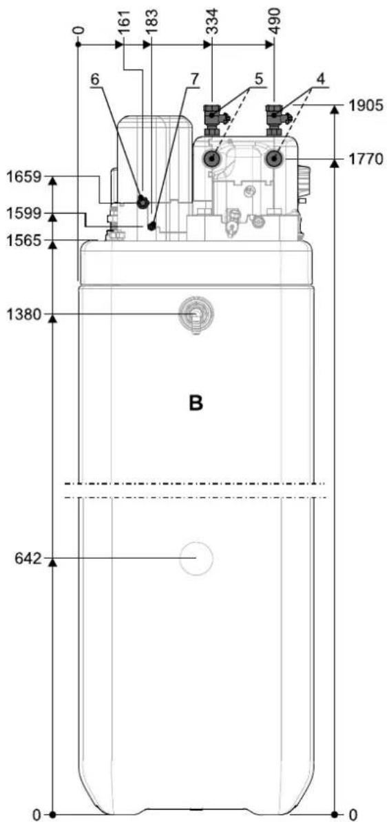
1 Solar feed
2 Cold water
3 Hot water
4 Heating feed
5 Heating return flow
6 Connection coolant gas line
Fig. 4-1 Dimensions and connections Daikin Altherma EHS(X/H)...P30B (general)
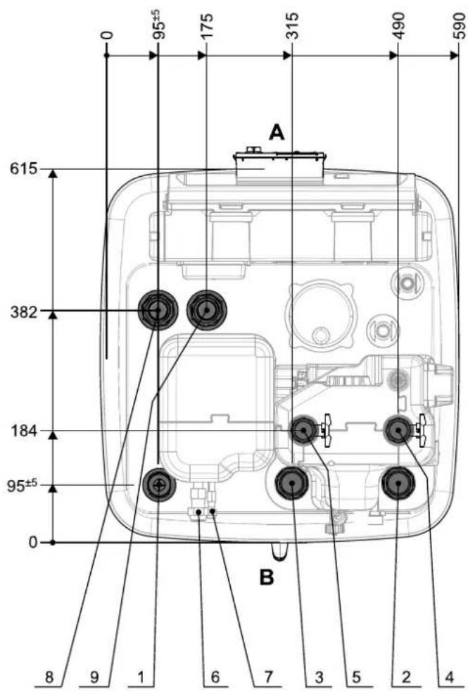
7 Connection coolant fluid line
8 Solar-feed flow (only Daikin Altherma EHS(X/H)B type)
9 Solar-return (only Daikin Altherma EHS(X/H)B type)
A Front
B Back
4.1.2 Daikin Altherma EHS(X/H)...P50B

1 Solar-feed
2 Cold water
3 Hot water
4 Heating feed
5 Heating return flow
6 Connection coolant gas line
7 Connection coolant fluid line
8 Solar-feed flow (only Daikin Altherma EHS(X/H)B type)
9 Solar return (only Daikin Altherma EHS(X/H)B type)
A Front
B Back
Fig. 4-2 Dimensions and connections Daikin Altherma EHS(X/H)...P50B (general)
4.1.3 Scope of delivery
– Daikin Altherma EHS(X/H)
– Bag of accessories (see fig. 4-3)
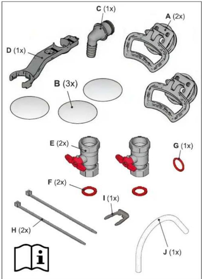
A Handles (only required for transport)
E Ball cock
B Cover screen
F Flat seal
C Hose connection piece for safety overflow
G O-ring
D Spanner
H Tie wraps
I Plug bracket
J Venting tube
Fig. 4-3 Content of bag of accessories
4.2 Set-up

CAUTION!
- Only erect the Daikin Altherma EHS(X/H) when a sufficient ground load-bearing capacity, of 1050 kg/m² plus safety margin, has been assured. The ground must be flat and level.
• Outdoor installation is not permitted. - Erection in explosion-risk environments is not permitted.
- The electronic control system must not be subjected to atmospheric factors under any circumstances.
- The storage tank must not be exposed to continuous direct sunlight, as the UV radiation and the effects of the weather will damage the plastic.
- The Daikin Altherma EHS(X/H) must be installed in a manner protected from frost.
- Make sure that the supply company does not provide corrosive domestic water.
- Suitable water treatment may be required.

WARNING!
The plastic wall of the storage tank on the Daikin Altherma EHS(X/H) may melt due to the effects of external heat (>80 °C) and in the extreme case, can catch fire.
- Erect the Daikin Altherma EHS(X/H) only at a minimum distance of 1 m to other heat sources (>80 °C) (e.g. electric heater, gas heater, chimney) and flammable materials.
CAUTION!
If the Daikin Altherma EHS(X/H) is not erected adequately lower the flat solar panels (the top edge of the of the storage tank is higher than the bottom edge of the solar panels), the unpressurised solar system in the outdoor area will be unable to drain completely.
- Erect the Daikin Altherma EHS(X/H) with a DrainBack solar connection at a sufficient depth to the flat solar panels (observe the minimum gradient in the solar connecting lines).
- Remove packing and dispose of it in an environment-friendly manner.
- Remove the cover plates on the storage tank (fig. 4-4, item B) and unscrew the threaded pieces (fig. 4-4, item F) from the apertures on which the handles are to be mounted (fig. 3-2 to fig. 3-5, item 24).
- Screw handles (fig. 4-4, item A) into the threaded holes that are now free.
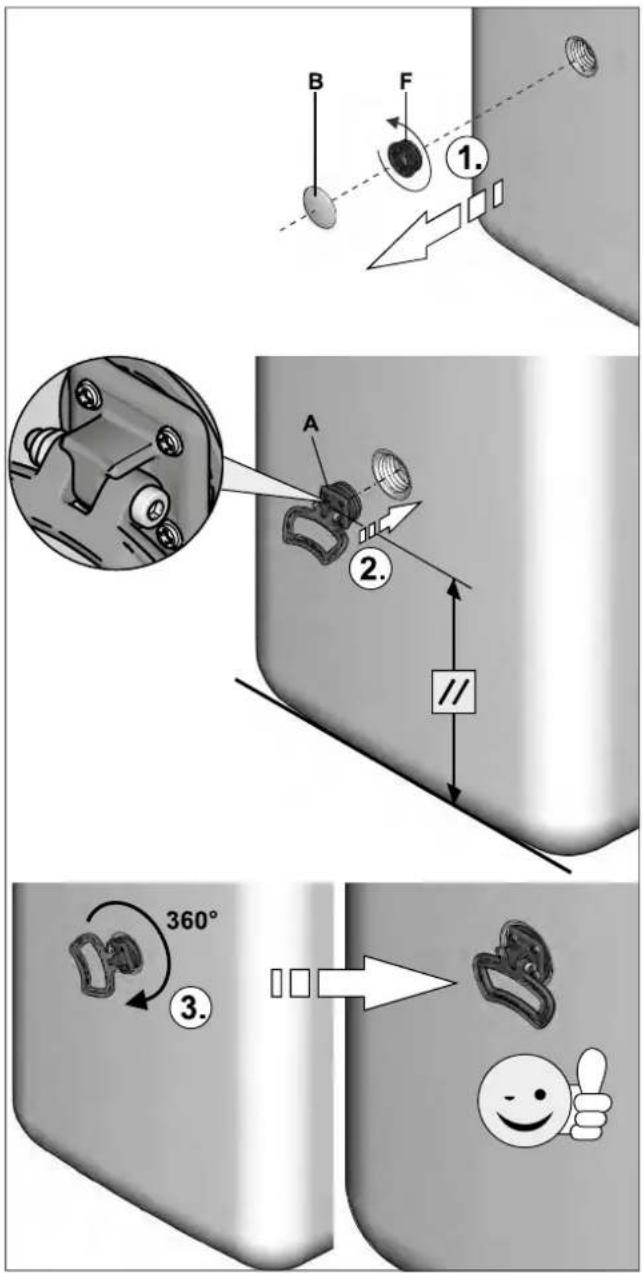
A Handle
B Cover screen
F Threaded piece
Fig. 4-4 Attach handles
4 Set-up and installation
• Install the Daikin Altherma EHS(X/H) at the installation site.
- Recommended clearances (fig. 4-5):
To the wall: (s1) ≥100 mm, (s2) ≥500 mm.
From the ceiling (X): ≥1200 mm, minimum 480 mm.
- Carefully transport the Daikin Altherma EHS(X/H), use the handles.
- When setting up the unit in a cabinet, behind panels or in other restricted conditions, sufficient ventilation (e.g., using ventilation gratings) must be ensured.
- If necessary, install the optional Backup-Heater (EKBUxx) into the Daikin Altherma EHS(X/H) (fig. 4-5).
Observe the assembly and operating manual supplied with the accessory (or tightening torque see chapter 10.3).
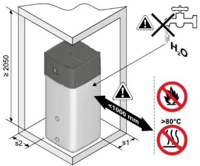
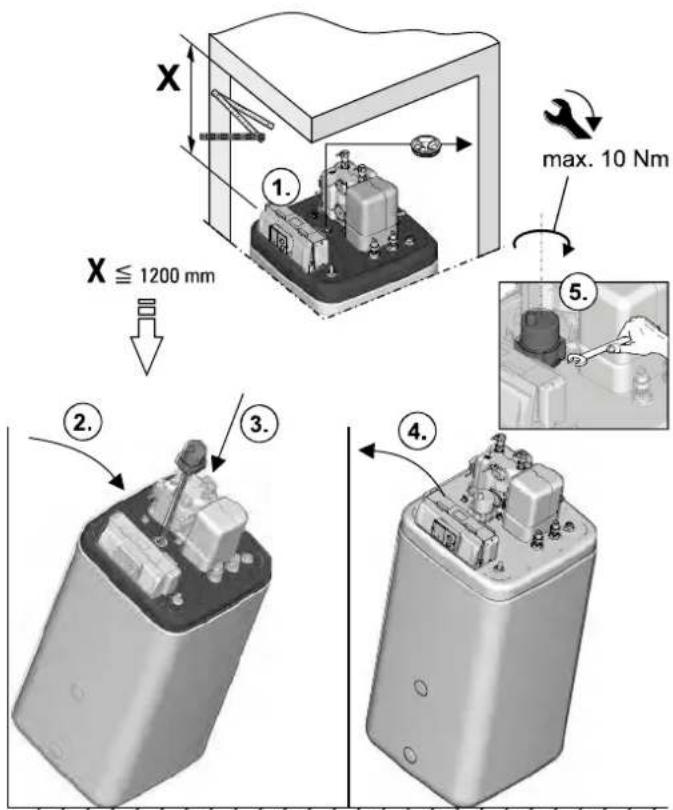
Fig. 4-5 Layout (shown on Daikin Altherma EHS(X/H) P50B with incorporation of the optional Backup-Heater)
4.3 Remove cover hood and heat insulation
- Lift the cover hood at the back and remove to the front.
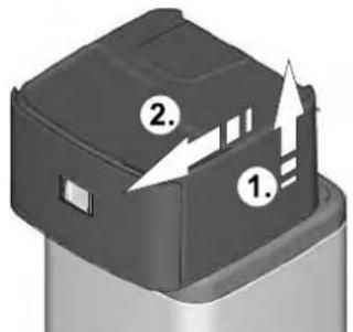
Fig. 4-6 Removing the protective cover
natural_image
Technical line drawing of an electrical enclosure with labeled components (no text or symbols present)Fig. 4-7 Daikin Altherma EHS(X/H) without cover hood

CAUTION!
The thermal insulation (fig. 4-7, item A) consists of pressure sensitive shaped EPP components that can easily be damaged by inappropriate handling.
- Carry out removal of the thermal insulation only in the sequence and in the directions quoted below.
- Do not use force.
-
Do not use tools.
-
Remove the top thermal insulation in the following order:
– Pull away the side insulation element (fig. 4-8, item A) horizontally.
– Pull away the rear insulation element (fig. 4-8, item B) horizontally.
– Pull away the front insulation element (fig. 4-8, item C) horizontally.
Fig. 4-8 Removing top thermal insulation
- If required: Remove the bottom thermal insulation in the following order:
– Pull away the side insulation element (fig. 4-9, item A) vertically.
– Pull away the rear insulation element (fig. 4-9, item B) vertically.
Fig. 4-9 Removing bottom thermal insulation

Installing the thermal insulation is carried out in the reverse order.
4.4 Water connection

CAUTION!
If the Daikin Altherma EHS(X/H) is connected to a heating system with steel pipes, radiators or non-diffusion-proof floor heating pipes, slurry and swarf could enter the hot water storage tank and cause blockages, local over-heating or corrosion.
- Flush the feed pipes before filling the heat exchanger.
- Rinse out the heat distribution network (in the existing heating system).
- Install the dirt filter or sludge separator into the heating return flow (see chapter 2.4.6).

CAUTION!
If the Daikin Altherma EHS(X/H) is connected to a cold water line, where steel pipes are used, chips can enter the special steel corrugated pipe heat exchanger and remain there. This can lead to contact corrosion damage and subsequently to leakage.
- Flush the feed pipes before filling the heat exchanger.
• Install contamination filter in the cold water feed (see chapter 2.4.6).

Only Daikin Altherma EHS(X/H)B...
CAUTION!
If the heat exchanger for charging the pressurised solar system (fig. 4-1 / fig. 4-2, item 8+9) has an external heating unit (e.g. wood-burning boiler) connected to it, an excessive flow temperature at these connections can damage or destroy the Daikin Altherma EHS(X/H) B.
- The feed flow temperature of the external heater should be limited to max. 95 °C.

In accordance with EN 12828 you must install a safety valve at or in the immediate vicinity of the heat exchanger, with which you can limit the maximum permissible operating pressure in the heating system. There should be no hydraulic blocking elements between the heat generator and the safety valve.
Any steam or heating water which may escape must be diverted by a suitable blow-off line with constant gradient in a frost-protected, safe and observable manner.
A diaphragm expansion vessel of adequate dimensions and pre-set for the heating system must be connected to the Daikin Altherma EHS(X/H). There should be no hydraulic blocking elements between the heat generator and the diaphragm expansion vessel.
Daikin recommends integrating a mechanical manometer for the filling of the heating system.
- For drinking water lines, comply with the EN 806 and DIN 1988 stipulations.
- Install the Daikin Altherma EHS(X/H) near to the removal point to dispense with the need for a circulation line. If a circulation line is absolutely essential, it must be installed in accordance with the schematics in section 9 "Hydraulic system connection".
4.4.1 Aligning the connections of the heating feed and return flow
The connections for the heating feed and return flow can be directed out of the unit upwards or downwards in order to adapt to the on-site conditions in the most optimum manner.
The unit is delivered with the connections exiting upwards as standard. In order to direct the connections out from the back of the unit you must carry out the following conversion steps:
- Remove the cover hood and the upper thermal insulation (see chapter 4.3).
Fig. 4-10 Heating feed and return flow connections aligned upwards
- Pull off both the plug brackets on the connection couplings (fig. 4-10, item C).
• Pull off both connection couplings (fig. 4-10, item B).

CAUTION!
When working on the hydraulics you must take care of the mounting position of the O-rings to prevent damage to the O-rings and consequent leaks.
- Always place O-rings on the part to be inserted after a plug connection has been removed or before it is installed.
-
Connection of heating lines by plug connection must be without tension. Establish suitable tension relief particularly for connection with flexible lines (not breathable!).
-
Remove retainer plate (fig. 4-10, item A).
• Pull off the plug bracket on the closing plug (fig. 4-10, item D).
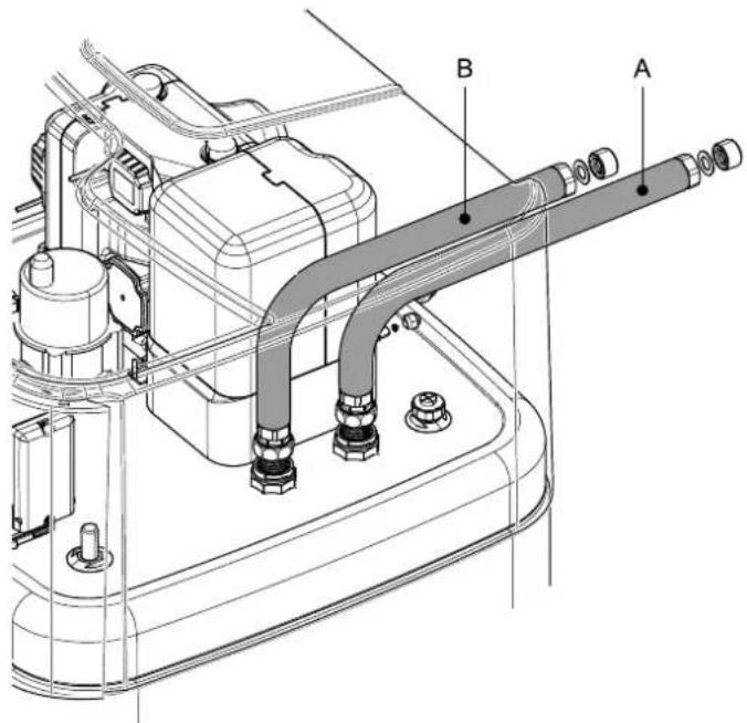
• Pull out the closing plug (fig. 4-10, item E). - Rotate the angular piece (fig. 4-10, item H) by 90^ to the back.
• Pull off the plug bracket on the elbow (fig. 4-10, item G). - Pull the elbow (fig. 4-10, item F) carefully to the rear out of its horizontal mount so that the retainer plate (fig. 4-11, item A) can be inserted in the gap vertically.
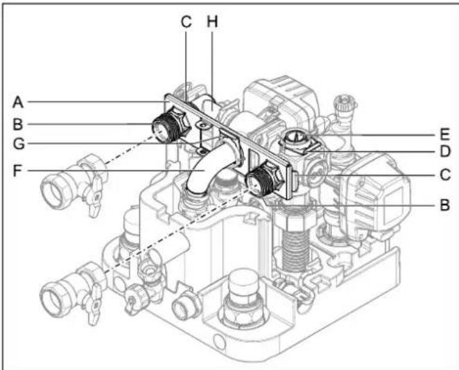
Fig. 4-11 Heating feed and return flow connections aligned to the rear
- Slide the retainer plate between the elbow and its horizontal mount and insert the elbow (fig. 4-11, item F) back in its mount through the central hole in the retainer plate.

CAUTION!
If the plug brackets are not inserted properly, the couplings can come loose in their mounts which may result in high levels of fluid escape and continuous fluid escape.
- Before plugging in a plug bracket, make sure that the plug bracket engages in the groove in the coupling. To do this, insert the coupling into the mount until the groove becomes visible through the plug bracket mount.
-
Insert the plug bracket up to the stop.
-
Secure the elbow back into its mount with plug bracket (fig. 4-11, item G).
- Insert both connection couplings (fig. 4-11, item B) through the retainer plate in the side mounts.
- Secure both connection couplings in their mounts with the plug brackets (fig. 4-11, item C).
- Insert the closing plug (fig. 4-11, item E) in the top mount.
- Secure the closing plug with the plug bracket (fig. 4-11, item D).
- Cut out the side transit points in the thermal insulation (fig. 4-12, item A) using a suitable tool.
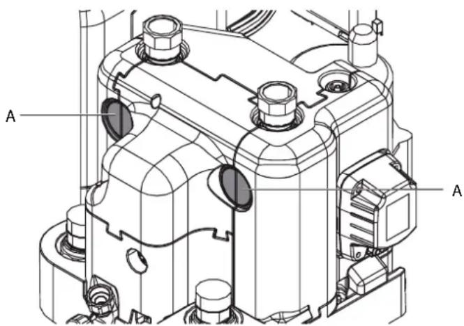
Fig. 4-12 Thermal insulation cut-out
4.4.2 Connecting hydraulic lines
Requirement: Optional accessories (e.g. Solar, Backup-Heater) mounted on the Daikin Altherma EHS(X/H) according to the specifications of the instructions included.
- Check cold water pressure (maximum 6 bar).
- At higher pressure in the drinking water line, a pressure reducer must be installed.
- Establish hydraulic connections at the Daikin Altherma EHS(X/H).
- Position and dimensions of the heating connections to be taken from fig. 4-1 / fig. 4-2 and from tab. 3-1.
- Pay attention to the stipulated tightening torque (see section 10.3 "Tightening torque").
- Design the lines as such that the sound attenuation cowl can be applied without any problem following assembly.
- Connect the water for filling or refilling the heating system as specified by EN 1717 to avoid contamination of drinking water by backwash.
- Connect a drain line to the safety overpressure valve and connect a diaphragm drain container in accordance with EN 12828.
- Check the seating of the drain hose on the overpressure valve.
- If required, attach your own hose and route accordingly.
- Carefully insulate pipe lines against heat loss and so as to avoid the formation of condensation (insulation thickness at least 20 mm).
- Water shortage protection: The pressure and temperature monitoring of the control unit safely switches off the Daikin Altherma EHS(X/H) in the event of a water shortage. No additional water shortage protection is needed in the construction.
- Avoid damages caused by deposits and corrosion: Observe the relevant regulations of technology to prevent creation of corrosion products and deposits.
Minimum requirements regarding the quality of filling and supplementary water:
– Water hardness (calcium and magnesium, calculated as calcium carbonate): ≤3 mmol/l
- Conductivity: 1500 (ideal 100) S/cm
- Chloride: 250 mg/l
– Sulphate: 250 mg/l
- pH value (heating water): 6,5 - 8,5
In the case of filling and top-up water with a high overall hardness or other properties that deviatte from the minimum requirements, measures for the desalination, softening, hardness stabilisation or other suitable conditioning measures are required to maintain the required water quality.

WARNING!
There is a danger of scalding at hot water temperatures over 60 °C. This is possible, when solar energy is used, with a connected external heating device, when the Legionella protection is activated or when the domestic hot water target temperature is set higher than 60 °C.
• Install scald protection (hot water mixer (e.g. VTA32).
- Connect the drain hose to the connection piece for the safety overflow (fig. 3-2 to fig. 3-5, item 23).
- Use transparent drain hose (draining water must be visible).
- Connect the drain hose to an adequately dimensioned waste water installation.
- Drain should not be lockable.
Fig. 4-13 Installation of drain hose at safety overflow
4.4.3 Assembly DB connection kit
The optional DB connection kit provides improved accessibility for connecting the DrainBack line (solar feed).
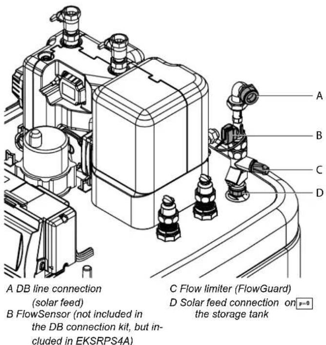
Fig. 4-14 DB connection kit
4.4.4 Assembly Biv connection kit
The optional P connection kit for Daikin Altherma EHS(X/H) Biv device types provides better access for connecting the feed and return flow of a pressurised solar system or another external heat generator to the storage tank. The kit contains two thermally insulated corrugated pipes that are connected to the connections on the storage tank with a union nut. At the other end of the corrugated pipe there is an adapter for each of the various different connection sizes of the feed and return flow line.
A Flow connection (red)
B Return flow connection (blue)
Fig. 4-15 Biv connection kit for Daikin Altherma EHS(X/H)B...
4.5 Electrical connection

WARNING!
Touching live parts can result in an electric shock and lead to potentially fatal injuries and burns.
- Before beginning work on live parts, disconnect all of the systems circuits from the power supply (switch off main switch, disconnect fuse) and secure against unintentional restart.
- The electrical connection and working on the electrical components should only be performed by electrical engineers in compliance with valid standards and guidelines as well as the specifications of the energy supply company.
- The equipment covers and maintenance opening covers must be re-fitted immediately after completion of the work.

CAUTION!
In the controller housing of the Daikin Altherma EHS(X/H), in continuous running, elevated temperatures can be generated. This can result in currently-carrying wires from reaching higher temperatures during operation due to self-heating. For this reason, these lines need to have a continuous use temperature of 90 °C.
- For the following connections, use only cables with a long-term use temperature ≥slant 90^ : - Exterior heat pump unit - Optional: Electrical Backup-Heater (EKBUxx)
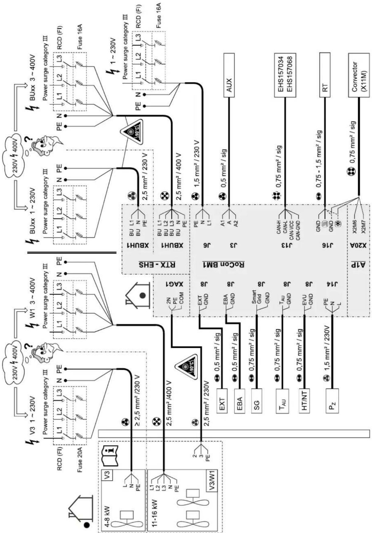
4.5.1 Overall connection plan Daikin Altherma EHS(X/H)

Explanation of symbols and abbreviations in this chapter see tab. 4-2 and tab. 4-3.
flowchart
graph TD
    A["4-8 kW V3"] --> B["RCD (FI)"]
    B --> C["Fuse 20A"]
    C --> D["≥ 2.5 mm² /230 V"]
    E["11-16 kW V3/W1"] --> F["EXT"]
    E --> G["EBA"]
    E --> H["SG"]
    E --> I["T_AU"]
    E --> J["HT/NT"]
    E --> K["P_Z"]
    D --> L["XAG1"]
    F --> M["XBUH1"]
    G --> N["XBUH1"]
    H --> O["XBUH1"]
    I --> P["AUX"]
    J --> Q["EHS157034 EHS157068"]
    K --> R["RT"]
    L --> S["X20A X2M6 X2M7"]
    M --> T["Convector (X11M)"]

    subgraph Power Surge Categories
        U["V3 1~230V"] --> V["W1 3~400V"]
        W["230V 400V"] --> X["W1 3~400V"]
        Y["BUxx 1~230V"] --> Z["BUX 3~400V"]
        AA["Power surge category III"] --> AB["Power surge category III"]
        AC["Power surge category III"] --> AD["Power surge category III"]
        AE["PE"] --> AF["PE"]
    end

    subgraph Grid Lines
        AG["XAG1"] --> AH["XBUH1"]
        AH --> AI["2.5 mm² / 230 V"]
        AJ["XBUH1"] --> AK["2.5 mm² / 400 V"]
        AL["XBUH1"] --> AM["2.5 mm² / 400 V"]
        AN["XBUH1"] --> AO["2.5 mm² / 400 V"]
        AP["XBUH1"] --> AQ["2.5 mm² / 400 V"]
        AR["XBUH1"] --> AS["2.5 mm² / 400 V"]
        AT["XBUH1"] --> AU["2.5 mm² / 400 V"]
        AV["XBUH1"] --> AW["2.5 mm² / 400 V"]
        AX["XBUH1"] --> AY["2.5 mm² / 400 V"]
        AZ["XBUH1"] --> BA["2.5 mm² / 400 V"]
        BB["XBUH1"] --> BC["2.5 mm² / 400 V"]
        BD["XBUH1"] --> BE["2.5 mm² / 400 V"]
        BF["XBUH1"] --> BG["2.5 mm² / 400 V"]
        BH["XBUH1"] --> BI["2.5 mm² / 400 V"]
        BJ["XBUH1"] --> BK["2.5 mm² / 400 V"]
        BL["XBUH1"] --> BM["2.5 mm² / 400 V"]
        BN["XBUH1"] --> BO["2.5 mm² / 400 V"]
        BP["XBUH1"] --> BQ["2.5 mm² / 400 V"]
        BR["XBUH1"] --> BS["2.5 mm² / 400 V"]
        BT["XBUH1"] --> BU["2.5 mm² / 400 V"]
        BV["XBUH1"] --> BW["2.5 mm² / 400 V"]
        BX["XBUH1"] --> BY["2.5 mm² / 400 V"]
        BZ["XBUH1"] --> CA["2.5 mm² / 400 V"]
        CB["XBUH1"] --> CC["2.5 mm² / 400 V"]
        DD["XBUH1"] --> DE["2.5 mm² / 400 V"]
        EF["XBUH1"] --> GF["2.5 mm² / 400 V"]
        GH["XBUH1"] --> ID["2.5 mm² / 400 V"]
        IJ["XBUH1"] --> AJ["2.5 mm² / 400 V"]
        AK["XBUH1"] --> AL["2.5 mm² / 400 V"]
        AM["XBUH1"] --> AN["2.5 mm² / 400 V"]
        AO["XBUH1"] --> AP["2.5 mm² / 400 V"]
        AQ["XBUH1"] --> AR["2.5 mm² / 400 V"]
        AS["XBUH1"] --> AT["2.5 mm² / 400 V"]
        AU["XBUH1"] --> AV["2.5 mm² / 400 V"]
        AW["XBUH1"] --> AX["2.5 mm² / 400 V"]
        AY["XBUH1"] --> AZ["2.5 mm² / 400 V"]
        BA["XBUH1"] --> BB["2.5 mm² / 400 V"]
        BC["XBUH1"] --> BD["2.5 mm² / 400 V"]
        BEX["XBUH1"] --> BF["2.5 mm² / 400 V"]
        BG["XBUH1"] --> BH["2.5 mm² / 400 V"]
        BI["XBUH1"] --> BJ["2.5 mm² / 400 V"]
        BK["XBUH1"] --> BL["2.5 mm² / 400 V"]
        BM["XBUH1"] --> BN["XBUH1"]
    end

    style Power Surge Categories fill:#f9f,stroke:#333
    style Grid Lines fill:#ccf,stroke:#333
    note right of AB
        note left of AB: Power surge category III
        note right of AB: Power surge category III
    end
Fig. 4-16 Overall connection diagram - for electrical connection during device installation
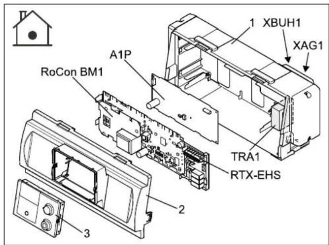
4.5.2 Position of the circuit boards
1 Control housing
3 Control section of the control
2 Control panel
Fig. 4-17 Overview circuit boards (internal housing)
4.5.3 Connection assignment, circuit board A1P
The A1P circuit board comes pre-connected to the unit. No assembly or connection work is necessary on the A1P circuit board!
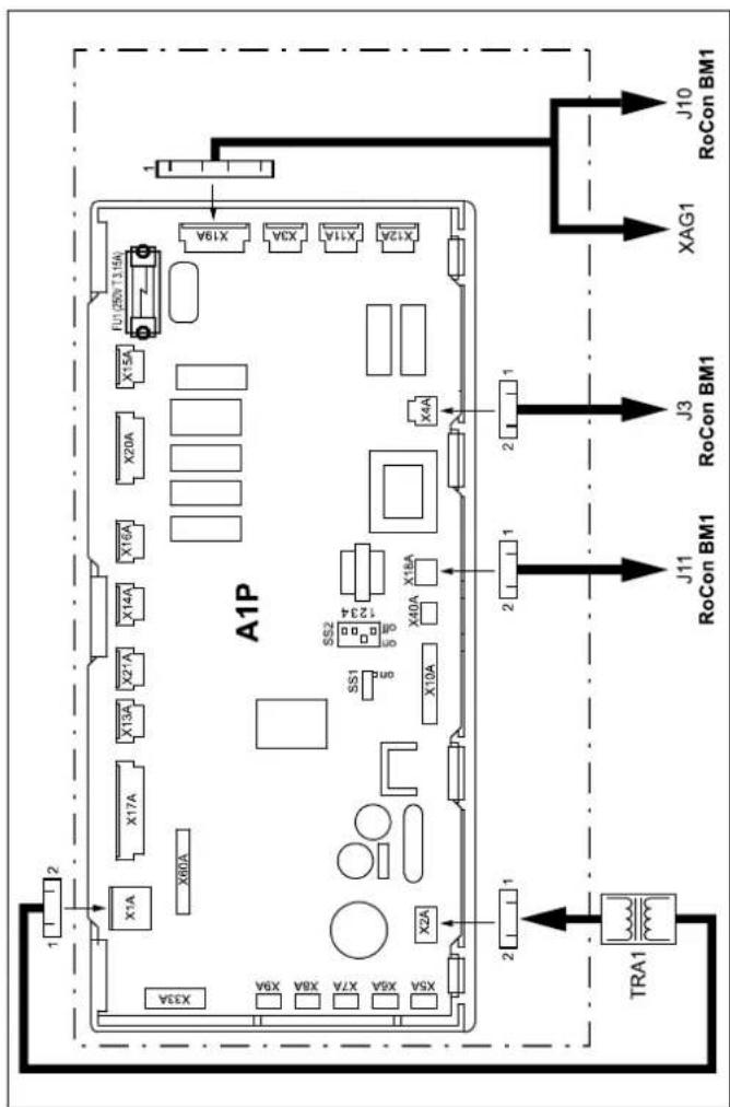
Fig. 4-18 Circuit board A1P (basic control of the heat pump)
4.5.4 Terminal assignment for the RTX-EHS circuit board
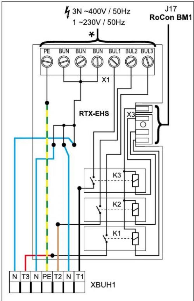
Fig. 4-19 Circuit board RTX-EHS (Backup-Heater) - see section 4.5.12
4.5.5 Connection assignment, circuit board RoCon BM1
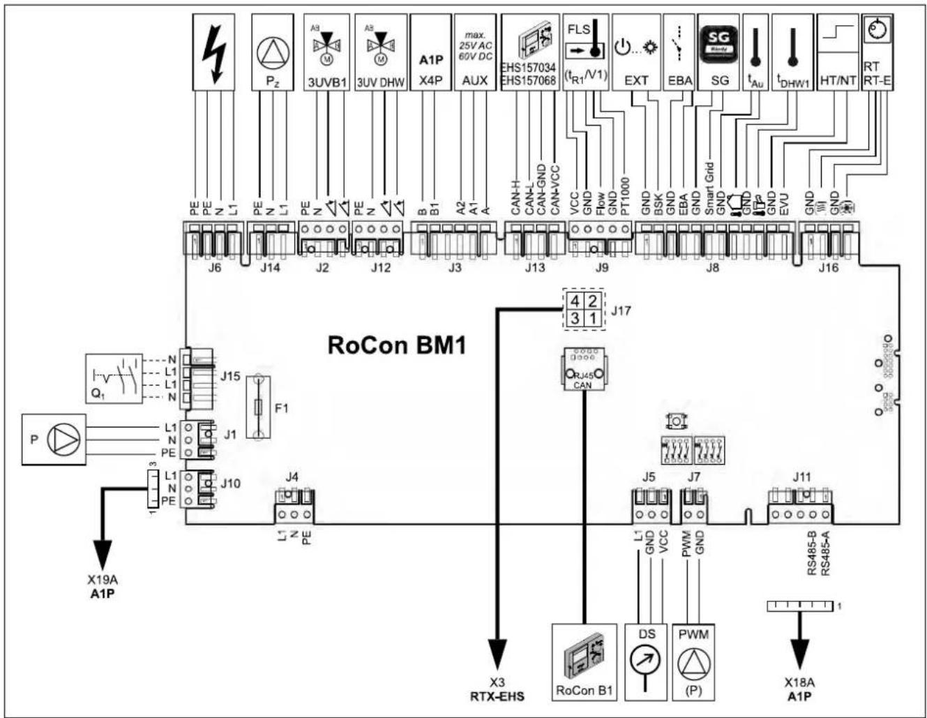
flowchart
graph TD
    A["PE PE Z L1 PE Z L1 PE Z"] --> B["J6"]
    C["Pz"] --> D["J14"]
    E["A3 M"] --> F["J2"]
    G["A8 M"] --> H["J12"]
    I["A1P X4P"] --> J["J3"]
    K["max. 25V AC 60V DC AUX"] --> L["J3"]
    M["EHS157034 EHS157068"] --> N["J13"]
    O["FLS (tR1/V1)"] --> P["J9"]
    Q["EXT"] --> R["J8"]
    S["SG"] --> T["J8"]
    U["tAu"] --> V["J16"]
    W["tDHW1"] --> X["HT/NT"]
    Y["RT RT-E"] --> Z["Q1"]
    AA["X19A A1P"] --> AB["J15"]
    AC["F1"] --> AD["J1"]
    AE["L1 N PE"] --> AF["J10"]
    AG["P"] --> AH["3 PE"]
    AI["ROCon BM1"] --> AJ["J17"]
    AK["RJ45 CAN"] --> AL["J4"]
    AM["X3 RTX-EHS"] --> AN["RoCon B1"]
    AO["DS"] --> AP["PWM (P)"]
    AQ["X18A A1P"] --> AR["X18A A1P"]
Fig. 4-20 Circuit board RoCon BM1 (masic control module)

Mains supply 230 V, 50 Hz (Connection plan in this instruction manual)
4.5.6 Mains connection Daikin Altherma EHS(X/H)
A flexible cable for the mains connection is already connected internal to the device.
- Check the supply voltage (\~230 V, 50 Hz).
- Disconnect the junction box of the domestic installation.
- Connect the cable for the mains connection on the Daikin Altherma EHS(X/H) to the junction box of the domestic installation via an all-pole disconnecting main switch to be installed by the customer (separate isolator according to EN 60335-1). Ensure that the polarity is correct.
The external device and optional accessories must be connected separately to the regulator on the Daikin Altherma EHS(X/H). To do so, the cover panel of the Daikin Altherma EHS(X/H) must be removed (see section 4.3) and if necessary, the control housing opened (see section 4.5.7).
4.5.7 Open controller housing and making the electrical connections
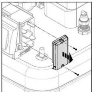
natural_image
Technical line drawing of a mechanical assembly with no visible text or symbolsFig. 4-21 Dismount right housing cover.

Fig. 4-22 Unlock front panel.
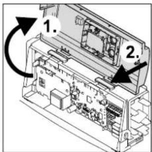
Fig. 4-23 Open front panel and place in assembly position.

Fig. 4-24 Route cabling into the regulator and make the electrical connections.
natural_image
Technical line drawing of a mechanical assembly with hoses and components (no text or symbols)Fig. 4-25 Lay cables in the right housing cover.

natural_image
Technical line drawing of a mechanical assembly with internal components and a central component (no text or symbols)Fig. 4-26 Install the right housing cover.
Fig. 4-27 Make the electrical connections to the rear of the housing (see section 4.5.1).
natural_image
Technical line drawing of a mechanical or electrical component with no visible text, numbers, or symbols.Fig. 4-28 Fasten cabling on the storage container.
4.5.8 Connection of ERLQ exterior heat pump unit

This component has a separate manual attached, including among other things instructions for installation and operation.
- Dismount the protective cover (see section 4.3).
- Connect the exterior heat pump unit to the terminal strip XAG1 (see fig. 4-27, fig. 4-29).
flowchart
graph TD
    A["XAG1"] -->|1 N| B["X1M"]
    A -->|PE| B
    A -->|COM| B
    B --> C["Ground Symbol"]
    style A fill:#f9f,stroke:#333
    style B fill:#ccf,stroke:#333
Fig. 4-29 Connection of exterior heat pump unit

When switching off the heat pump exterior unit using a switching system prescribed by the energy supply company (EVU), the internal Daikin Altherma EHS(X/H) device is not disconnected (see section 4.5.18).
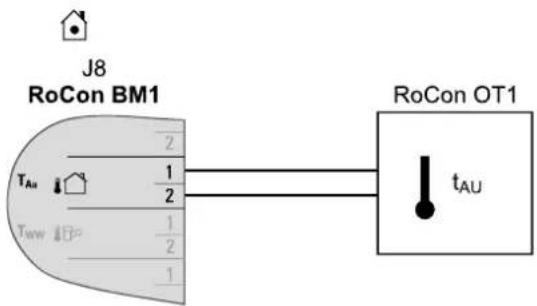
4.5.9 Connection of external temperature sensor RoCon OT1
The exterior heat pump unit of the Daikin Altherma EHS(X/H) has a built-in exterior temperature sensor which is used to regulate the inflow temperature depending on the weather, with frost protection function.
The weather-controlled flow temperature regulation can be optimised with the RoCon OT1 optional external temperature probe, which can be installed on the north face of the building.

If the Daikin Altherma EHS(X/H) is used in a CAN bus system as a master ("terminal function" for the remote control of other data bus devices), the exterior temperature sensor RoCon OT1 must be connected directly to the regulator RoCon HP on the master and not to the remote controlled device (mixer circuit module EHS157068 or a different heat generator).
Choose a location at about one third of the building height (minimum distance from floor: 2 m) at the coldest side of the building (North or North-East). Thereby, exclude the proximity of external heat sources (chimney, air shafts) and direct sunshine.
- Place external temperature sensors in such a way that the cable exit points face downwards (prevents humidity ingress).

CAUTION!
The parallel routing of sensor and mains lines within an installation pipe can cause considerable malfunctioning in the regular operation of the Daikin Altherma EHS(X/H).
• Always lay the sensor line separately.
4 Set-up and installation
- Connect the exterior temperature sensor to a twin-core sensor line (minimum diameter 1 mm ^4 ).
• Install the sensor line to the Daikin Altherma EHS(X/H). - Connect the sensor line to the plug connection J8 on the board RoCon BM1 (see fig. 4-30).
flowchart
graph LR
    A["RoCon BM1"] -->|2| B["RoCon OT1"]
    A -->|1/2| B
    A -->|1/2| B
    A -->|1| B
    A -->|1| B
    A -->|1| B
    style A fill:#f9f,stroke:#333
    style B fill:#ccf,stroke:#333
Fig. 4-30 Connection of the exterior temperature sensor RoCon OT1 to the Daikin Altherma EHS(X/H) (operating as a single solution or master in a data bus)
After connecting the exterior temperature sensor RoCon OT1 to the regulator RoCon HP of the Daikin Altherma EHS(X/H), the parameter [Outside Config] must be set to "On".
4.5.10 Connection of an external switching contact
By connecting an external switching contact (fig. 4-31) the operating mode of the Daikin Altherma EHS(X/H) can be changed.
The current operating mode can be switched thanks to a changing resistance reading (tab. 4-1). Changing the operating mode is only effective as long as the external switching contact is closed.
The operating mode has an effect on the direct circuit of the Daikin Altherma EHS(X/H), and on all other heating circuits that can be optionally connected to this device.
The operating mode shown in the controller display can deviate from the operating mode activated in the rotary switch setting ⏻...
An operating mode activated by an external switch contact is shown on the controller by "EXT.", followed by the symbol of the operating mode (see operating instructions for the controller).
If special functions, such as "Manual Operation" are activated, the input is not evaluated.
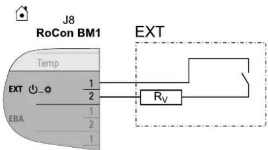
Fig. 4-31 Connection of the EXT switching contact
| Operating mode Res | stance R v | Tolerance |
| Standby < 680 | Ω | ±5% |
| Heating 1200 | Ω | |
| Reducing 1800 | Ω | |
| Summer 2700 | Ω | |
| Automatic 1 4700 | Ω | |
| Automatic 2 8200 | Ω |
Tab. 4-1 Resistance values for the evaluation of the EXT signal
When the resistance readings are greater than the value for "Automatic 2", the input will be ignored.
NOTE REGARDING THE CONNECTION OF A DAIKIN SOLAR SYSTEM
By means of the function [HZU] integrated into the RoCon HP integrated HZU control unit (see operating manual for the control unit) it is not necessary to connect the EXT connection with the connection of the burner blocking contact of the Daikin solar system.
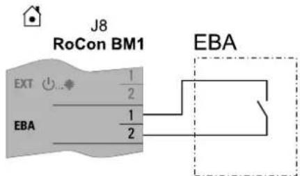
4.5.11 External demand signal (EDS)
By connecting the EDS switch contact to the Daikin Altherma EHS(X/H) (fig. 4-32) and through the corresponding parameterisation in its RoCon HP control unit, a heating demand can be generated via an external switch contact. If the switch contact is closed, the Daikin Altherma EHS(X/H) switches to the heating mode. The flow temperature is adjusted to the temperature that is set in the parameters [T-Flow Day].
The EDS switching contact has preference of a request via the room thermostat.
In Cooling, Stand-by, Manual and Summer mode, the switching contact is not evaluated. In addition, the heating limits are not taken into consideration.
flowchart
graph TD
    A["RoCon BM1"] --> B["EXT"]
    A --> C["EBA"]
    D["EBA"] --> E["1/2"]
    D --> F["1/2"]
    G["EBA"] --> H["2"]
    I["J8"] --> J["Extralation Point"]
    style A fill:#f9f,stroke:#333
    style D fill:#ccf,stroke:#333
    style G fill:#cfc,stroke:#333
Fig. 4-32 Connection EBA switch contact
4.5.12 Connection of the electrical Daikin Backup-Heater (EKBUxx)

This component has a separate manual attached, including among other things instructions for installation and operation.
- Connect the power supply for the Backup-Heater to the terminal rail X1 of the switch board RTX-EHS (fig. 4-19) in the regulation housing of the Daikin Altherma EHS(X/H).
- Insert the plug XBUH1 of the Backup-Heater on the back of the regulation housing of the Daikin Altherma EHS(X/H).
- Set parameter [Function Heating] to "1" (see controller operating instructions RoCon HP).
Connection variant 1

3N \~400V / 50Hz EKBU9C
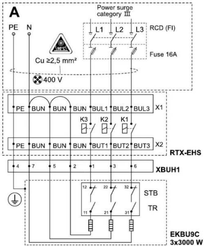
A Cabling provided by the customer (observe country-specific connection conditions - request from responsible power company (EVU))!
Fig. 4-33 3-phase connection, Backup-Heater (EKBU9C)
Connection variant 2
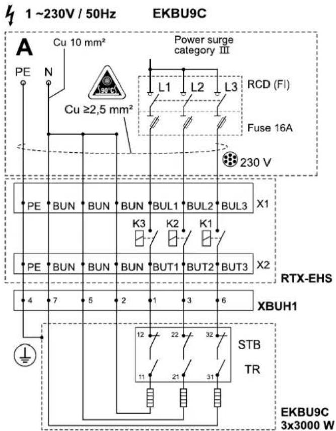
Fig. 4-34 Single phase connection Backup-Heater (EKBU9C) (for legend see fig. 4-33)
Connection variant 3 4.5.13 Connection of an external heat generator

When connecting a Backup-Heater with a heating element the parameter [EKBU1C / EKBU3C), Function Heating ]=2 must be set.
↓
1 \~230V / 50Hz 1000 W EKBU1C (1x 1000 W) 1 \~230V / 50Hz 3000 W EKBU3C (1x 3000 W)
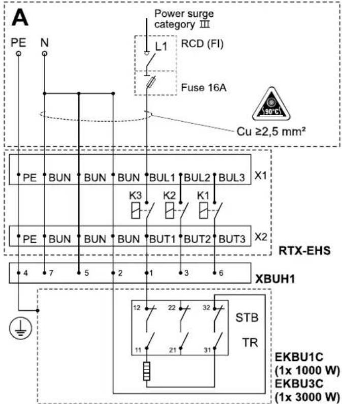
Fig. 4-35 Connection Backup-Heater with a heating element (EKBU1C / EKBU3C) (for legend see fig. 4-33)

Warning!
When contacting a damaged connection cable of the Backup-Heater this can cause electrocution and thus cause life-threatening injury and burns.
- Do not repair the connection cable of the Backup-Heater.
→ Always replace the complete Backup-Heater.
For heating support or as an alternative to an electrical Backup-Heater (see section 4.5.12) you can connect an external heat generator (e.g. gas or oil boiler) to the Daikin Altherma EHS(X/H).
The heat supplied by the external heat generator must be added to the unpressurised storage tank water in the Daikin Altherma EHS(X/H) hot water storage tank.
- Carry out hydraulic connection in accordance with one of the two following possibilities:
a) unpressurised via connections (solar infeed and solar return) of the hot water tank or
b) oh+whit types Daikin Altherma EHS(X/H) B, via the integrated pressurised solar heat exchanger.
- Observe the instructions concerning hydraulic connections (see chapter 2.4)
– Examples of hydraulic connection (see chapter 9).
Demand from an external heat generator is switched to the RTX-EHS circuit board via a relay (see fig. 4-36). The electrical connection to the Daikin Altherma EHS(X/H) is possible as follows;
a) External heat generator has a potential-free switch contact connection for heat demand:
- Connection to K3, if the external heat generator takes over the hot water generation and heating support (setting parameter [Function Heating] = 2) or
- Connection to K1 and K3 if two external heat generators are being used (setting parameter [Function Heating] = 3). Here K1 switches the external heat generator (e.g. gas or oil boiler) for heating support and K3 the external heat generator (EKBUxx) for hot water generation.
- Connection on AUX connection A (see section 4.5.17)
b) External heat generator can only be switched via the mains power supply: Connection (\~230 V, maximum load 3000 W) at K1 and K3.

Caution!
Risk of voltage arcing.
- The connections on the RTX-EHS circuit board must not be used for switching the mains voltage (\~230 V) and protective low voltage (SELV = "Safety Extra Low Voltage") at the same time.
- Suitable electrical connection from the relevant installation instructions for the external heat generation.
- Connect external heat generation to the Daikin Altherma EHS(X/H) (fig. 4-36).
Connection X1 is a screw terminal.
Isolated 6.3 x 0.8 mm push-on receptacles are required for connections X2_1/2/3.
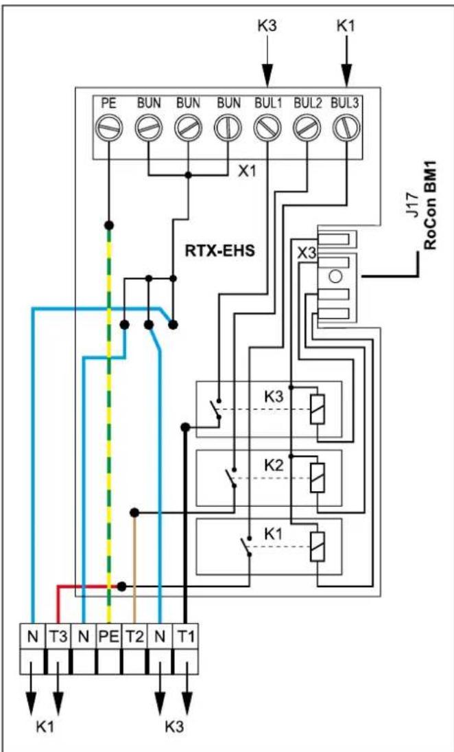
flowchart
graph TD
    A["PE"] --> B["BUN"]
    B --> C["BUN"]
    C --> D["BUN"]
    D --> E["BUL1"]
    E --> F["BUL2"]
    F --> G["BUL3"]
    G --> H["X1"]
    H --> I["RTX-EHS"]
    I --> J["X3"]
    J --> K["K1"]
    K --> L["K3"]
    L --> M["N T3 N PE T2 N T1"]
    M --> N["K1"]
    N --> O["K3"]
    O --> P["K1"]
    P --> Q["K3"]
    Q --> R["K1"]
    R --> S["K3"]
    S --> T["K1"]
    T --> U["K3"]
    U --> V["K1"]
    V --> W["K3"]
    W --> X["K1"]
    X --> Y["K3"]
    Y --> Z["K1"]
    Z --> AA["K3"]
    AA --> AB["K1"]
    AB --> AC["K3"]
    AC --> AD["K1"]
K1/2/3
Relay for Backup-Heater
L Phase
N Neutral
PE Protective earth conductor
RTX-EHS
Switch board (Backup-Heater)
Fig. 4-36 Connections on RTX-EHS circuit board
X1 Terminal block for mains connection to Backup-Heater
X3 Plug connection internal cabling to RoCon BM1 circuit board
4.5.14 Connection of the Daikin room thermostat

This component has a separate manual attached, including among other things instructions for installation and operation.
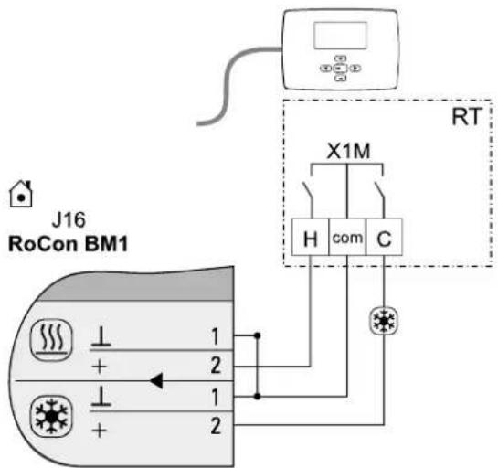
Fig. 4-37 Connection with wired room thermostat (RT = Daikin EKRTW)
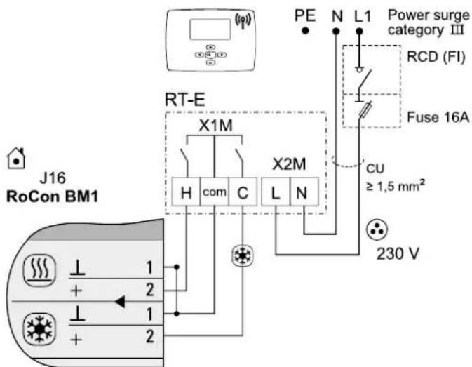
Fig. 4-38 Connection with radio room thermostat (RT-E = Daikin EKRTR)
4.5.15 Connection optional RoCon system components
The optional RoCon devices must be connected to the Daikin Altherma EHS(X/H) using a 4-core CAN bus cable (connection J13).
Daikin recommends screened cables with the following characteristics for this purpose:
– Standard to ISO 11898, UL/CSA type CMX (UL 444)
– PVC outer sheath with flame retardant to IEC 60332-1-2
- Up to 40m , minimum cross-section area 0.75mm^2 .
For greater lengths, use larger cross-section areas.
Commercially available junction boxes can be used for connection of Can bus lines of several RoCon devices.
Ensure power cables, sensor cables and data bus cables are laid separately from each other. Use only cable trunking with separate trays or cable trunking with separators that ensure at least 2 cm spacing. Cable crossings are permissible.
The entire RoCon system can have a maximum of 16 devices connected with a total cable length up to 800 m.
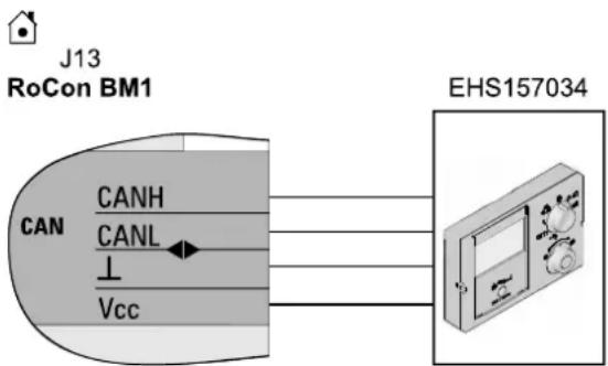
Room station EHS157034
For the remote setting of operating modes and room target temperatures from a different room, a separate room station EHS157034 can be connected for each heating circuit.

This component has a separate manual attached, including among other things instructions for installation and operation.
flowchart
graph LR
    A["J13 RoCon BM1"] --> B["CAN"]
    B --> C["CANH"]
    B --> D["CANL"]
    B --> E["Vcc"]
    F["EHS157034"] --> G["Device"]
Fig. 4-39 Connection room station EHS157034
Mixer module EHS157068
The Daikin Altherma EHS(X/H) can be connected to the EHS157068 mixer module, which is controlled via the RoCon HP electronic controller.
The connection of the CAN data bus lines is identical to the fig. 4-39 to connection J13 of the Daikin Altherma EHS(X/H).

This component has a separate manual attached, including among other things instructions for installation and operation.
Internet gateway EHS157056
The controller can be connected to the internet via the optional EHS157056 gateway. This means that the Daikin Altherma EHS(X/H) can be controlled remotely via mobile phone (using an App).

This component has a separate manual attached, including among other things instructions for installation and operation.
4.5.16 Connection of the Daikin FWXV(15/20)AVEB

This component has a separate manual attached, including among other things instructions for installation and operation.
– Electrical connection of the Daikin FWXV(15/20)AVEB with the following accessories in accordance with fig. 4-40 as a changeover contact (heating/cooling) on the basic module.
- Connect genuine Daikin connecting cable (HPc-VK-1) to Daikin Altherma EHSX, so that the Daikin FWXV(15/20)AVEB switches the operating mode (heating/cooling) together with the Daikin Altherma EHSX.
- Install and connect 2-way valve (2UV) (HPC-RP) in the Daikin FWXV(15/20)AVEB. Adjust its regulation so that the 2-way valve (2UV) provides isolation if there is no demand for this unit.

Mode (heating/cooling) can only be switched on the Daikin Altherma EHS(X/H).
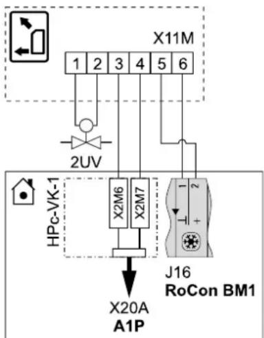
flowchart
graph TD
    A["X11M"] --> B["1"]
    A --> C["2"]
    A --> D["3"]
    A --> E["4"]
    A --> F["5"]
    A --> G["6"]
    H["HPc-VK-1"] --> I["X20A"]
    H --> J["A1P"]
    K["X2M6"] --> I
    L["X2M7"] --> I
    M["J16 RoCon BM1"] --> N["1"]
    M --> O["2"]
Fig. 4-40 Connecting the Daikin FWXV(15/20)AVEB to the Daikin Altherma EHS(X/H)
4.5.17 Connection switch contacts (AUX outputs)
The switch contacts (AUX outputs) can be used for various different functions that can be parametrised.
The switching contact A-A1-A2 switches as configured in the parameter [AUX Fct] (see operating manual for the control unit).
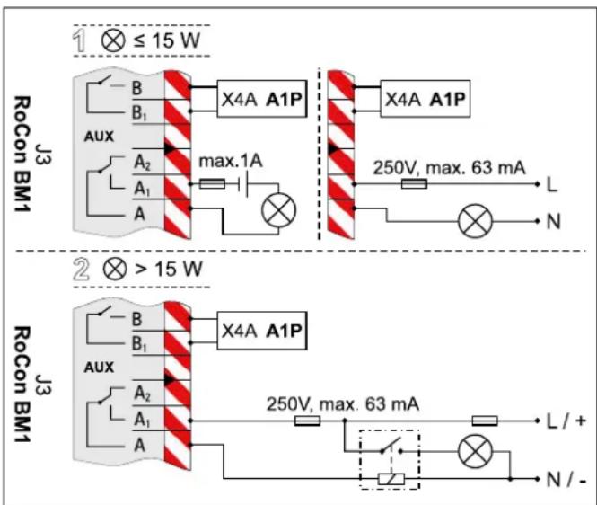
Fig. 4-41 Connection switching contact (AUX output)
The relays to be used for Variant 2 (switched power > 15 W) must be suitable for 100 % switch-on duration.
The switch-over contact A-A1-A2 can be used, for example, to control the heat generator in bivalent heating systems of Daikin Altherma EHS(X/H) and oil or gas boiler. Examples of the hydraulic system incorporation are shown in chapter 9.
4.5.18 Low tariff mains connection (HT/NT)
If the outdoor unit is connected to a reduced tariff mains connection, the voltage-free switching contact S2S of the receiver which evaluates the low tariff input signal emitted by the electricity supply company (EVU) must be connected to the plug J8, connection EVU on the RoCon BM1 circuit board (see fig. 4-42).
When the parameter [HT/NT Function] > 0 is set, certain system components are switched off during peak tariff times (see operating manual of the control unit).
The following types of reduced tariff mains connection are standard:
- Type 1: With this type of low-tariff mains connection, the power supply to the heat pump exterior unit is not disconnected.
- Type 2: With this type of low-tariff mains connection, the power supply to the heat pump exterior unit is disconnected after a certain period of time.
- Type 3: With this type of low-tariff mains connection, the power supply to the heat pump exterior unit is disconnected immediately.
The potential-free switching contact S2S can be designed as a normally-closed or a normally-open switching contact.
a) If it is designed as an open switching contact, then the parameter [HT/NT Contact] = 1 must be set.
If the EVU transmits the reduced tariff signal, switching contact S2S is opened. The system switches to "Mandatory OFF". If the signal is sent again, the potential-free switching contact S2S closes and the system resumes operation.
b) If it is designed as an closed switching contact, then the parameter [HT/NT Contact] = 0 must be set.
If the EVU transmits the reduced tariff signal, switching contact S2S is closed. The system switches to "Mandatory OFF". If the signal is sent again, the potential-free switching contact S2S opens and the system resumes operation.
$$ [ \mathrm{HT/NTContact} ] = 1 [ \mathrm{HT/NTContact} ] = 0 $$
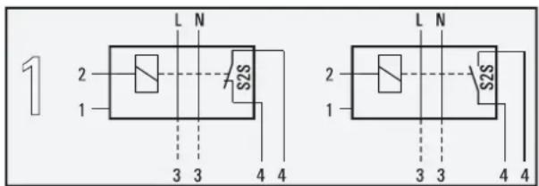
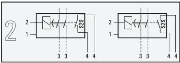
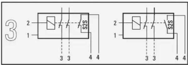
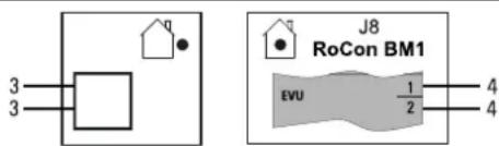
1 Mains connection boxes for reduced-tariff mains connection
2 Recipient for evaluation of the HT/NT control signal
3 Power supply to heat pump exterior unit (see relevant instruction manual for the heat pump exterior unit)
4 Potential-free switching contact for heat pump interior unit
Fig. 4-42 Connection HT/NT switching contact
4.5.19 Connection intelligent controller (Smart Grid - SG)
Once the function is activated by parameter [SMART GRID] = 1 (see operating manual for the control unit), depending on the signal from the energy supply company, the heat pump is switched to Stand-by, Normal or an operating mode with higher temperatures.
To do so, the potential-free contacts SG1/SG2 of the intelligent controller must be connected to the J8 plug, connections Smart Grid and EVU, on the RoCon BM1 circuit board (see fig. 4-43).
As soon as the Smart Grid function is active, the HT/NT function is deactivated automatically. Depending on the value of the parameter [Mode SG] the heat pump operated in a different manner (see operating manual for the control unit).
flowchart
graph TD
    A["RoCon BM1"] --> B["SmartGrid"]
    B --> C["SG"]
    D["T_Ax"] --> E["1/2"]
    F["T_WW"] --> G["1/2"]
    H["EVU"] --> I["1/2"]
    J["SG1"] --> K["1"]
    L["SG2"] --> M["1"]
Fig. 4-43 Connection Smart Grid
4.5.20 Symbols and legend keys on connection and circuit diagrams
| Symbols Explanation Symbols Explanation | |||
| [ST84] | Safety earthing | External cabling (number of individual cores and the mains voltage are partially quoted.) | |
| [50C4] | Low external voltage earthing Pushbutton | ||
 | Connection terminal DIP switch | ||
| [6KGY] | Plug connection Optional component | ||
 | Terminal rail Plug and socket connection | ||
| [YYWO] | 2-core cabling (non-screened) 3-core cabling (non-screened) | ||
 | 4-core cabling (non-screened) 5-core cabling (non-screened) | ||
 | 6-core cabling (non-screened) Shielded cabling (for example 3-strand) | ||
Tab. 4-2 Symbol explanations for connection and circuit diagrams
| Key names | |||||
| Short designation | Explanation Short | designation | Explanation | ||
| ERLQ | External unit for heat pump FU1 Fuse 250 V T 3,15 | A (A1P) | |||
| EHS(X/H) | Heat pump indoor unit FLS Flow sensor (t | _R1/V1 | |||
| 3UVB1 | 3-way diverter valve (internal heat generation circuit) | HPc-VK-1 | Connecting cable between Daikin Altherma EHS(X/H) B (with cooling function) and FWXV(15/20)AVEB | ||
| 3UV DHW 3 w | way diverter valve (hot water/heating) HT/NT | Switching contact for reduced-tariff mains connec-tion | |||
| A1P Circuit board (basic control of the heat pump) P Heat circulation pump (devce-internal) | |||||
| A1P | X1A Plug connection to TRA1 (230 V) P | z | Circulation pump | ||
| X2A Plug connection to TRA1 (12 V) PWM Pump connection (PWM signal) | |||||
| X3A Plug connection internal cabling (strapping plug) RJ45 | CAN | Plug connection (Rocon BM1) internal cabling (to RoCon B1) | |||
| X4A | Plug connection to J3 from RoCon BM1 | RoCon B1 | Operating section of the controller | ||
| X5A Plug connection flow temperature sensor t V1 | RoCon BM1 | Circuit board (basic control model) | |||
| X6A Flow temperature sensor plug connection t V,BH | RoCon BM1 | J1 | Plug connection for heat circulation pump P | ||
| X7A | Plug connection temperature sensor (fluid-side coolant) t_L2 | J2 | Plug connection 3UVB1 | ||
| X8A | Return flow temperature sensor plug connection t_R2 | J3 | Plug connection AUX switching contacts | ||
| X9A | Storage tank temperature sensor plug connection t_DHW2 | J4 | Plug connection - Not occupied | ||
| X18A | Plug connection to J11 from RoCon BM1 | J5 | Plug connection pressure sensor | ||
| X19A | Plug connection to XAG1 + J10 from RoCon BM1 | J6 | Plug connection mains voltage | ||
| X21A | Plug connection internal cabling (strapping plug) | J7 | Plug connection PWM - Signal for heat circulation pump P | ||
| AUX | Outputs switch contacts (A-A1-A2) + (B-B1) | Plug connection EXT | |||
| EKBUxx Back | up-Heater | connection EBA | |||
| DS | Pressure sensor | Plug connection Smart Grid switch contact EVU | |||
| EBA | Switching contact for external demand signal | Plug connection exterior temperature sensor t_AU | |||
| EXT | Switching contact for external operating mode switching | Storage tank temperature sensor plug connection t_DHW1 | |||
| F1 Fuse 250 V T 2 A (RoCon BM1) | option HT/NT switching contact EVU | ||||
Tab. 4-3 Key names for connections and circuit diagrams - Part 1
4 Set-up and installation
| Key names | ||||
| Short designation | Explanation Short | designation | Explanation | |
| RoCon BM1 | J9 Plug | connection FLS (t R1/ V1) SG | Switching contact for Smart Grid (intelligent mains connection) | |
| J10 Plug | connection internal cabling to X19A (A1P) TRA1 T | Transformer | ||
| J11 Plug | connection internal cabling to X18A (A1P) t | AU | External temperature sensor (RoCon OT1) | |
| J12 Plug | connection 3UV DHW t | DHW1 | Storage tank temperature sensor 1 (RoCon BM1) | |
| J13 Plug | connection System-Bus (e.g. room station) t | DHW2 | 2 (A1P) storage tank temperature sensor | |
| J14 Plug | connection circulation pump P z | tR1 | Return flow temperature sensor 1 (FLS - RoCon BM1) | |
| J15 Plug | connection internal cabling (strapping plug) t | R2 | Return flow temperature sensor 2 (A1P) | |
| J16 | Plug connection room thermostat (EKRTR / EKRTW) | tV1 | Flow temperature sensor 1 (A1P) | |
| EHS157068 Mixer module t | V, BH | Flow temperature sensor Backup-Heater (A1P) | ||
| EHS157034 Room station V1 Flow sensor (FLS - RoCon BM1) | ||||
| Cooling output | Output status for "Cooling" operating mode XAG1 | Plug connection | exterior heat pump unit | |
| RT | Room thermostat (EKRTW) | XBUH1 | Plug connection Backup-Heater (EKBUxx) | |
| RT-E | Receiver for radio room thermostat (EKRTR) | X2M6 | Connecting cable clamp HPc-VK-1 | |
| RTX-EHS | Switch board (Backup-Heater) | X2M7 | Connecting cable clamp HPc-VK-1 | |
| RTX-EHS | K1 | Relay 1 for Backup-Heater | X11M | Terminal block in FWXV(15/20)AVEB |
| K2 | Relay 2 for Backup-Heater | |||
| K3 | Relay 3 for Backup-Heater | |||
| X1 | Terminal block for mains connection to Backup-Heater | |||
| X3 | Plug connection internal cabling to J17 (RoCon BM1) | |||
Tab. 4-4 Key names for connections and circuit diagrams - Part 2
4.6 Laying coolant lines
- Check whether oil trap arc necessary.
- Required if Daikin Altherma EHS(X/H) is not installed at ground level with the heat pump exterior unit (fig. 4-44, H_0 ≥ 10 m).
- At least one oil trap arc must be installed every 10 m difference in height (fig. 4-44, H = clearance from oil trap arc to oil trap arc).
– Oil trap arc only required in gas line.
- Install lines with bending unit and an adequate clearance to electrical lines.
• Only solder with light nitrogen flow (hard soldering only). - Do not apply heat insulation to joins until after start-up (for purposes of leakage search).
- Establish flange connections and connect to the units. (Ray attention to the tightening torque, see section 10.3 "Tightening torque").
A Exterior heat pump unit (ERLQ)
B Daikin Altherma EHS(X/H)
C Gas line
D Liquid line
E Oil trap arc
H Height to 1st oil trap (max. 10 m)
H_O Height difference between heat pump exterior unit and heat pump interior unit.
Fig. 4-44 Oil trap arc coolant line
4.7 Pressure test and filling the coolant circuit

RISK OF ENVIRONMENTAL DAMAGE!
Important information regarding the coolant used.
The entire heat pump system contains refrigerant with fluoridated greenhouse gases which damage the environment if released.
Coolant type: R410A
GWP* value: 2087,5
* GWP = Global Warming Potential
- Fill in the total coolant filling quantity on the supplied label on the heat pump exterior unit (for information consult the installation instructions for the heat pump exterior unit).
- Never allow coolant to be released into the atmosphere - always suction it off and recycle using a suitable recycling device.
• Perform pressure test with nitrogen.
- Use nitrogen 4.0 or higher.
- Maximum 40 bar.
• After leak search is complete, completely drain.
- Vacuum lines.
- Pressure to be achieved: 1 mbar absolute.
– Time: minimum 1 h
- Check whether additional coolant is needed for primer filling, fill where necessary.
- Open stop valve on exterior unit completely until the stop. Tighten loosely.
- Reassemble valve caps.
- Check whether the storage tank temperature sensors t_DHW1 and t_DHW2 are inserted to a depth of 80 cm.
4.8 Filling the system with water
Only fill the Daikin Altherma EHS(X/H) following the sequence stated below and once all installation work is complete.
4.8.1 Checking the water quality and adjusting the pressure gauge
- Observe the information on the water connection and water quality in accordance with section 4.4.
The correct minimum pressure marking must be set on the pressure gauge installed by the customer before filling the system for the first time:
- Rotate the pressure gauge glass in such a way that the minimum pressure mark corresponds to the system height +2 m (1 m water column = 0.1 bar).
4.8.2 Filling the hot water heat exchanger
- Open the shutoff valve for the cold water supply pipe.
- Open the hot water tap connections so that the draw-off volume can be set as high as possible.
- Once water has been discharged from the tap connections, do not interrupt the cold water flow; this will ensure that the heat exchanger will be fully vented and that any impurities or residue will be discharged.
4.8.3 Filling the storage tank
See chapter 7.3.
4.8.4 Filling the heating system
See chapter 7.4.
5 Start-up

WARNING!
A Daikin Altherma EHS(X/H) that is installed or started incorrectly may not operate properly and is dangerous for the health and safety of individuals.
- The Daikin Altherma EHS(X/H) may only be started up by authorised and trained heating experts.

CAUTION!
A Daikin Altherma EHS(X/H) not put into operation properly can lead to damage to property and the environment.
- Observe the relevant regulations of technology to prevent creation of corrosion products and deposits. Minimum requirements regarding the quality of filling and supplementary water:
- Water hardness (calcium and magnesium, calculated as calcium carbonate): ≤slant mmol/l
- Conductivity: ≤500 (ideal ≤100) \$/cm
- Chloride: ≧250 mg/l
- Sulphate: ≧250 mg/l
- pH value (heating water): 6.5 - 8.5.
- The domestic water quality must comply with the EU Guideline 98/83 EC and the regionally-applicable regulations.
- During system operation, the water pressure at the pressure gauge must be checked at regular intervals. If necessary, readjust by refilling
5.1 Initial start-up

Read chapter 2.4 thoroughly before carrying out the steps described here.
After the Daikin Altherma EHS(X/H) was installed and connected completely, it will need to be undergo a one-time adaptation to the installation environment to be carried out by technical personnel (configuration).
After this configuration is complete, the installation is ready for operation and the operator can make additional custom configurations on it.
The heating specialist must instruct the operator [on using the machine], must prepare the commissioning report, and fill out the operating manual.
The settings of the optional components such the room thermostat or Daikin solar installation must be configured on the respective components themselves.
5.1.1 Requirements
- The Daikin Altherma EHS(X/H) is fully connected.
- The coolant system is dehumidified and filled with the specified amount of coolant.
- The heating and hot water systems are filled and charged at the right pressure (see chapter 7.4).
- The storage tank is filled up to the overflow (see chapter 7.3).
- Optional accessories have been mounted on and connected up.
– The control valves of the heating system are open.
5.1.2 Start-up
• Turn power supply to Daikin Altherma EHS(X/H) on.
→ After the start phase, the operating language selector is displayed.
- Use the rotary switch to select the desired language.

The operating language can be changed again at any time.
- Confirm the changes with a brief push of the rotary switch.
→ The Daikin Altherma EHS(X/H) Basic Configuration is loaded.
→ The message "Starting Up" is displayed.
→ The message "Initialization" is displayed.
→ The standard display for the current rotary switch setting is displayed.
5.1.3 Set the commissioning parameters
To set the commissioning parameters, the heating expert must be logged into the controller.
- Technician login
flowchart
graph TD
    A["Configuration"] --> B["Setup"]
    B --> C["System"]
    C --> D["Setup"]
    D --> E["Language"]
    E --> F["Date"]
    F --> G["Setup"]
    G --> H["Keylock Function"]
    H --> I["Access Rights"]
    I --> J["Outdoor type"]
    J --> K["Access Rights Access Rights"]
    K --> L["0 0 0 0"]
    L --> M["2 s"]
    N["Access Rights"] --> O["* 0 0 0"]
    O --> P["3x"]
    P --> Q["Access Rights"]
    Q --> R["User"]
    R --> S["Access Rights"]
    S --> T["Expert"]
    T --> U["✓"]
    U --> V["2 s"]
    V --> W["End"]
Fig. 5-1 Enter technician code
- Set required commissioning parameters. Here the supplied "Commissioning Checklist" is to be observed and completed.
- For clarification of the operating parameters, see Operating Manual of the Control Unit.
- Enter configuration values into the corresponding tables in the "Notes" chapter of the Operating Manual for the Control Unit.
- Activate Legionella protection ([Anti-Legionella day] parameter) if required.
- With connected external temperature RoCon OT1, set the parameter [Outside Config] to "On".
- Configure additional commissioning parameters depending on the system requirements for the control unit of the Daikin Altherma EHS(X/H).
flowchart
graph TD
    A["Configuration"] --> B["System"]
    B --> C["Power DHW BUH s1 power"]
    C --> D["Setup"]
    D --> E["Language Date"]
    style A fill:#f9f,stroke:#333
    style B fill:#ccf,stroke:#333
    style C fill:#cfc,stroke:#333
    style D fill:#fcc,stroke:#333
    style E fill:#ffc,stroke:#333
Fig. 5-2 Setting the commissioning parameters
5.1.4 Venting the hydraulics

If the storage temperature falls below a certain minimum value, the safety settings of the Daikin Altherma EHS(X/H) prevent the operation of the heat pump in the case of low external temperatures:
- External temperature < -2^ , minimum storage temperature = 30^
- External temperature < 12^ C ,minimum storage temperature = 23^ C .
Without backup-heater:
The storage tank water must be heated to the minimum required storage temperature by an external heater.
With Backup-Heater (EKBUxx):
With an outdoor temperature < 12^ and a storage tank temperature < 35^ , the Backup-Heater (BUH) is switched on automatically on in order to heat up the storage tank water to at least 35^ .
- In order to accelerate the heating process with the back-up heater, temporarily
- Set parameter [Function Heating] = "1" and
- Set parameter [Power DHW] to the maximum value of the back-up heater.
- Switch the rotary switch to operating mode and set the parameter [1x Hot Water] to "On". Following successful heating, reset the parameters to "Off".
- Make sure that the cap on the automatic venting unit is open (fig. 5-3, item A).
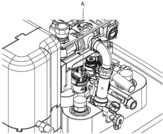
natural_image
Technical line drawing of a mechanical assembly with pipes and housing (no text or symbols)Fig. 5-3 Cap on the automatic venting unit
- Fit a hose to the manual venting valve (fig. 5-4, item B) and direct the hose away from the device. Open the valve until water comes out.
- Fit a hose to the second manual venting valve (fig. 5-4, item C) and open until water comes out.
- Activate the venting function (see FA RoCon HP).
By activating the Air Purge the RoCon HP control unit starts a defined sequence program with Start-Stopp operation of the integrated heat circulation pump and various settings for the 3-way diverter valve integrated into the Daikin Altherma EHS(X/H).
Existing air can leak from the automatic venting valve during the venting function and the hydraulic circuit connected to the Daikin Altherma EHS(X/H) is evacuated.

The activation of this function does not replace the correct venting of the heating circuit.
Prior to activating this function, the heating circuit must be completely filled.
- Check the water pressure and top up with water if necessary (see chapter 7.4).
- Repeat the venting, checking and topping-up process until: a) venting is complete. b) adequate water pressure is generated.
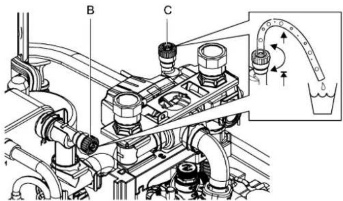
Fig. 5-4 Manual venting valves
5.1.5 Check the minimum flow rate
The minimum flow must be checked with a closed heating circuit.

If the minimum flow is too low, an error message may appear and the heating system may shut down.
If the minimum flow is insufficient:
– there may be air in the circulation pump.
→ Vent the circulation pump.
- the valve drive of the 3-way diverter valve (3UVB1 / 3UV DHW) is defective.
→ Check the function of the valve drive, if necessary, replace valve drive.
- Close valves and actuators of all closed heat distribution circuits.
- Set "Heating" operating mode on the control unit of the Daikin Altherma EHS(X/H).
- Read info parameter [Flow Rate].
→ The flow rate must be at least 600 l/h (see operating manual of the control unit).

The Daikin Altherma EHS(X/H) controller permanently monitors the flow of the internal heat exchanger circuit. Various different minimum flow rates are required depending on the active operating mode:
- Operating mode "Heating": 600 l/h
- Operating mode "Cooling": 840 l/h
- Automatic defrosting function ( ) active: 1020 l/h
If, at a flow rate in excess of 600 l/h, an error message concerning inadequate minimum flow is displayed, you must check the actual flow rate in the active operating mode and rectify any possible causes of the error.
5.1.6 Configuring Screed Program parameters (only if necessary)
With the Screed Program the flow temperature is controlled on the basis of a pre-set temperature profile.
Further information on the Screed Program, its activation and expiry, see the operating manual of the control unit.
After expiry of the Screed Program the RoCon HP control unit continues to operate in the previously set operating mode. Unless configured previously, the following tasks need to be carried out in conclusion.
a) When connecting without a room station EHS157034:
- Set the heating characteristic curve or the desired flow temperature.
b) When connecting with a room station EHS157034:
- Activate the room station.
- Set the heating characteristic curve or the desired flow temperature. If required, activate the parameter [Room Influence] and set the preset room temperature.
5.2 Re-commissioning
5.2.1 Requirements

CAUTION!
Commissioning in frosty conditions can result in damage to the entire heating system.
- Only commission at temperatures below 0 °C when a water temperature of at least 5 °C can be guaranteed in the heating system and storage tank. Daikin recommends that you avoid operating the system in extremely frosty conditions.
– The Daikin Altherma EHS(X/H) is fully connected.
- The coolant system is dehumidified and filled with the specified amount of coolant.
– The heating and hot water systems are filled and charged at the right pressure (see chapter 7.4).
- The storage tank is filled up to the overflow (see chapter 7.3).
5.2.2 Start-up

If the storage temperature falls below a certain minimum value, the safety settings of the Daikin Altherma EHS(X/H) prevent the operation of the heat pump in the case of low external temperatures:
- External temperature < -2^ , minimum storage temperature = 30^ - External temperature < 12^ , minimum storage temperature = 23^ .
Without backup-heater:
The storage tank water must be heated to the minimum required storage temperature by an external heater.
With Backup-Heater (EKBUxx):
With an outdoor temperature < 12^ and a storage tank temperature < 35^ , the Backup-Heater (BUH) is switched on automatically on in order to heat up the storage tank water to at least 35^ .
- In order to accelerate the heating process with the back-up heater, temporarily
- Set parameter [Function Heating] = "1" and
- Set parameter [Power DHW] to the maximum value of the back-up heater.
-
Switch the rotary switch to operating mode and set the parameter [1x Hot Water] to "On". Following successful heating, reset the parameters to "Off".
-
Check the cold water connection and where necessary, fill the potable water heat exchanger.
- Turn power supply to Daikin Altherma EHS(X/H) on.
- Wait for the start phase.
- After the start phase has completed, in heating mode, vent the heating system, check the system pressure and adjust if necessary (max. 3 bar, see chapter 7.4).
-
Carry out a visual inspection for leaks on all joints internally. Seal any leaks that occur in a professional manner.
-
Set the dial on the controller to the required operating mode.
- If a Daikin solar system is connected, commission this in accordance with instructions provided. After disconnecting the Daikin solar system, check the level in the buffer storage tank once again.
6 Decommissioning

WARNING!
Danger of scalding and flooding when opening the solar return flow coupling or heating and hot water pipes due to escaping hot water.
- Only drain the storage tank container or heating system
– when they have been left to cool sufficiently,
– with a suitable device for the safe draining or catching of escaping water, - wearing appropriate protective clothing.
6.1 Temporary shutdown

CAUTION!
A heating system which is shut down can freeze in the event of frost and may suffer damage.
- If there is any risk of frost, drain any water from the decommissioned heating system.
- If the heating system is not drained and there is a risk of frost, the power supplies must be secured and the external main switch must remain switched on.
If the Daikin Altherma EHS(X/H) is not needed for a long time, it can be temporarily decommissioned.
Daikin therefore recommends that you do not disconnect the system from power supply, but rather only place it in "Stand-By Mode" (consult the operating manual for the control system).
The system is then protected from frost. The pumps and valve protection functions are active.
If it is not possible to guarantee the power supply when there is danger of frost,
– completely discharge the Daikin Altherma EHS(X/H) on the water side, or
- suitable antifreeze measures must be taken for the connected heating system and hot water storage tank (e.g. draining).

If there is a danger of frost and the power supply cannot be guaranteed for just a few days, the unit's excellent heat insulation means that the Daikin Altherma EHS(X/H) does not have to be drained, provided that the storage tank temperature is monitored regularly and does not fall below +3 °C.
However, this does not provide frost protection for the connected heat distribution system.
6.1.1 Draining the storage tank
- Disconnect the Daikin Altherma EHS(X/H) from the power supply.
- Connect the outlet hose to the KFE filling connection (accessory KFE BA) (fig. 6-1, item A) and run to a drainage point that is at least soil deep.

If no KFE filling connection is available, the connection piece (fig. 6-1, item C) can alternatively be removed from the safety overflow (fig. 6-1, item B) and used.
Once the drainage process is complete, this must be replaced before the heating system can be started again.
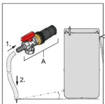
Fig. 6-1 Connecting the drain hose
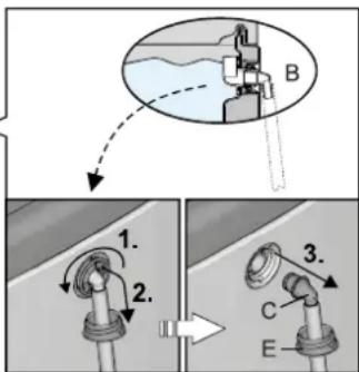
Optional: Removing the connection piece from the safety overflow
A KFE filling connection (accessory KFE BA)
B Safety overflow
C Hose connection piece for safety overflow
D Clamping piece
E Threaded piece
F Sealing plug
G Connecting angle
X Valve insert
Tab. 6-1 Legend from fig. 6-1 to fig. 6-6
Without solar installation
- Remove the cover plate from the filling and emptying fitting.
- When using the KFE filling connection (accessory KFE BA): Remove the cover plate from the handle and unscrew the threaded piece (fig. 6-2, item E) from the storage tank container.
Fig. 6-2 Unscrew threaded piece
6 Decommissioning
- Insert the KFE filling connection into the threaded piece (fig. 6-3, item E) and secure it using a clamping piece (fig. 6-3, item D).
- Place a suitable collection trough beneath the filling and emptying fitting.
- At the filling and emptying connection, unscrew the threaded piece (fig. 6-4, item E), remove the sealing plug (fig. 6-4, item F) and immediately screw the pre-assembled threaded insert with the KFE filling connection back into the filling and emptying connection (fig. 6-4).

CAUTION!
Storage water will gush out as soon as the sealing plug is removed.
Fig. 6-3 Complete KFEfilling connection
Fig. 6-4 Screw the KFE filling connection into the filling and draining fitting
- Open the KFE cock on the KFE filling connection and drain the water out of the storage tank.
Only for the solar installation
- Adjust the valve insert on the connecting angle so that the path to the blind plug is blocked off (fig. 6-5).
- Remove the blanking plug from the connecting elbow (fig. 6-5) and place a suitable collection trough beneath the unit.
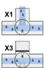
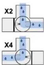


Fig. 6-5 Shutting off the valve insert and removing the blanking plug from the connecting angle
- Insert the KFE filling connection into the connecting elbow and secure using a retaining clamp (fig. 6-6).
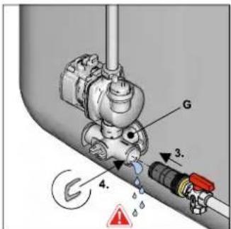
Fig. 6-6 Assembling the KFE filling connection in the connecting elbow
- Open the KFE filling connection.
- Adjust the valve insert on the connecting angle so that the flow to the drain hose is opened (also refer to fig. 6-5) and drain the water content of the storage tank.
6.1.2 Draining the heating circuit and hot water circuit
- Connect the drain hose to the combined filling and draining valve on the Daikin Altherma EHS(X/H).
- Open the combined filling and draining valve on the Daikin Altherma EHS(X/H).
- Allow the heating and hot water circuit to drain.
- Disconnect the heating flow and return flow as well as the cold water inflow and the hot water outflow from the Daikin Altherma EHS(X/H).
- Connect the discharge hose on the heating flow and return flow as well as the cold water inflow and hot water outflow so that the hose opening is at ground level.
- Allow the individual heat exchangers to run empty one after the other, using the suction lifter method.
6.2 Final shutdown

WARNING!
Cooling systems (heat pumps), climate control systems and heating devices that are incorrectly dismantled can both endanger the life and health of people and exhibit impaired function during start-up.
- Work on the Daikin Altherma EHS(X/H) (such as dismantling components, temporary or final shutdown of system) is only to be carried out by persons who are authorised and who have successfully completed qualifying technical or vocational training for the specific activity and who have taken part in advanced training sessions recognised by the relevant responsible authorities. These include, in particular, certified heating engineers, qualified electricians and HVAC specialists, who on account of their professional training and expert knowledge, have experience in the professional installation and maintenance of heating, cooling and air conditioning systems and heat pumps.
- You must observe the warning and safety instructions in the installation manual on working in the coolant system.
A final shutdown may be necessary if
– the system is defective and is being dismantled and disposed of.
- components of the system are defective, are being dismantled and replaced.
– the system or parts of the system are being dismantled and reassembled in another location.
The Daikin Altherma EHS(X/H) is designed to be environmentally friendly and easy to install: the jobs described above can therefore be carried out in an efficient and environmentally-friendly manner.
When changing location or replacing parts on the coolant system in the pipe network:
- Pump the coolant back into the external heat pump unit (see installation and operating guide for the particular external heat pump unit).
When disposing of the machine or replacing parts in the coolant system:
- Suction the coolant from the machine and recycle (see installation and operating guide for the particular external heat pump unit).

CAUTION!
Coolant escaping from the system causes long-term damage to the environment.
Mixing different kinds of coolant can result in hazardous toxic gases being released. Mixing with oils when coolant escapes can lead to the soil being contaminated.
- Never allow coolant to be released into the atmosphere - always suction it off and recycle using a suitable recycling device.
- Always recycle coolant, in so doing keeping it separated from oils and other additives.
- Only store different types of coolant separately, in suitable pressure vessels.
-
Dispose of coolants, oils and additives properly and in accordance with the applicable national regulations of the country it is being used in.
-
Decommissioning a Daikin Altherma EHS(X/H) (see section 6.1).
- Disconnect the Daikin Altherma EHS(X/H) from all electrical connections, refrigerant and water connections.
- Dismantle the Daikin Altherma EHS(X/H) or components in accordance with the installation guide in reverse order.
- Daikin Altherma EHS(X/H) disposed off in a professional manner.
Recommendations for disposal
The Daikin Altherma EHS(X/H) has an environmentally friendly design. During the disposal process, the only waste created is that which can be used for material or thermal recycling. The materials used that are suitable for recycling can be sorted into individual types.

Daikin has complied with the standards for environmentally-friendly disposal as a result of the environmentally-friendly design of the Daikin Altherma EHS(X/H). Proper disposal in compliance with the respective national regulations of the country of use is the responsibility of the user/owner.
The designation of the product means that electrical and electronic products may not be disposed of together with unsorted domestic waste.
Proper disposal in compliance with the respective national regulations of the country of use is the responsibility of the user/owner.
- Disassembly of the system, handling of coolant, oil and other parts may only be carried out by a qualified fitter.
- Disposal may only be carried out by an organization that specialises in reuse, recycling and recovery.
Further information is available from the installation company or the responsible local authorities.
7 Service and maintenance
7.1 General
Regular inspection and maintenance of the Altherma EHS(X/H) reduces energy consumption and ensures a long life and smooth operation.

RISK OF ENVIRONMENTAL DAMAGE!
Important information regarding the coolant used.
The entire heat pump system contains refrigerant with fluoridated greenhouse gases which damage the environment if released.
Coolant type: R410A
GWP* value: 2087,5
* GWP = Global Warming Potential
- Fill in the total coolant filling quantity on the supplied lable on the heat pump exterior unit (for information consult the installation instructions for the heat pump exterior unit).
- Never allow coolant to be released into the atmosphere - always suction it off and recycle using a suitable recycling device.

Have the inspection and maintenance carried out by authorised and trained HVAC engineers once a year, ideally before the heating period. This can prevent faults during the heating period.
Daikin recommends an inspection and maintenance contract to ensure regular inspection and maintenance.
Legal requirements
According to the F-Gases Directive (EC) No. 842/2006 Article 3, replaced on 01.01.2015 by (EC) No. 517/2014 Articles 3 and 4, Operators (or Owners) must perform regular maintenance on their fixed cooling systems, check impermeability and have any leaks repaired immediately.
All installation, maintenance and repair work on the cooling circuit must be documented e.g. in the operating manual.
Operators of Daikin heat pump systems are subject to the following obligations:

The European statutory investigation period applies for heat pumps from a total system coolant filling quantity of 3 kg or, as of 01.01.2017 from a total filling quantity of 5 t CO _2 -equivalent (in the case of R410A from 2.4 kg).
Daikin nonetheless recommends the conclusion of a maintenance contract, including documentation of the work carried out in the operating manual in order to preserve the right to guarantee, including for systems for which there is not legal obligation to monitor impermeability.
- With a system coolant total filling quantity of 3 kg – 30 kg or from 6 kg in hermetic systems and from 01.01.2017 with a total filling quantity of 5-50 t CO 2 -equivalent or from 10 t CO 2 -equivalent in hermetic systems:
→ Inspections carried out by certified personnel at intervals of no more than 12 months and documentation of the work performed in accordance with valid regulations. This documentation must be retained for at least 5 years.

Certified people are those who have proof of expertise for the European Community for work on stationary refrigeration systems (heat pumps) and air conditioning systems, according to the F-Gases Directive (EC) 303/2008.
– up to 3 kg coolant fill quantity: Expert certificate category II
- 3 kg coolant fill quantity or over: Expert certificate category I
7.2 Activities to be performed annually

WARNING!
Improperly carried out work on the Daikin Altherma EHS(X/H) and its components that have been connected as an option can endanger human life and health and adversely affect the operation of the these components.
- Work on the Daikin Altherma EHS(X/H) (such as maintenance or servicing) is only to be carried out by persons who are authorised and who have successfully completed qualifying technical or vocational training and who have taken part in advanced training sessions recognised by the appropriate responsible authorities. These include in particular certified heating engineers, qualified electricians and HVAC specialists, who because of their professional training and expert knowledge, have experience in the professional installation and maintenance of heating, cooling and air conditioning systems and heat pumps.

WARNING!
The gaseous coolant is heavier than air. In pits or in badly ventilated rooms it can collect in high concentrations. Breathing in high concentrations of gaseous coolant leads to feelings of faintness and suffocation. Toxic gases can be formed if gaseous coolants come into contact with open fire or hot objects.
- When working on the refrigerant circuit, ensure that the workplace is well ventilated.
- If necessary, before starting work, evacuate the coolant system completely.
- Never carry out work on the refrigerant circuit in closed rooms or work pits.
- Do not let refrigerant come into contact with open fire, embers or hot objects.
- Never allow coolant to escape into the atmosphere (forms high concentrations).
- After removing the service pipes from the filling connections, carry out a leakproof test on the refrigeration system. coolant can escape through leaks.

WARNING!
At normal atmospheric pressure and ambient temperatures, liquid coolant vaporises so suddenly that on contact with skin or eyes it can cause the tissue to freeze (danger of going blind).
- Always wear safety goggles and protective gloves.
- Never allow refrigerant to escape into the atmosphere (high pressure at the point of the leak).
- When removing the service pipes from the filling connections, never hold the connections in the direction of your body. Residual refrigerant could escape.

WARNING!
Under the cover of the Daikin Altherma EHS(X/H) temperatures of up to 90 °C can arise during operation. During operation, hot water temperatures > 60 °C arise.
- Touching components during or after operation leads to a risk of burns.
– Water discharged during maintenance and servicing work can cause scalding on contact with the skin. - Before carrying out servicing and maintenance work, allow the Daikin Altherma EHS(X/H) to cool down sufficiently.
- Wear protective gloves.

WARNING!
Live parts can cause an electric shock on contact and cause fatal burns and injuries.
- Before beginning work on live parts, disconnect all of the systems circuits from the power supply (switch off main switch, disconnect fuse) and secure against unintentional restart.
- Electrical connection and work on electrical components must only be carried out by qualified electricians in compliance with valid standards and guidelines as well as the specifications of the energy supply company.
-
Covers off equipment and servicing flaps are to be replaced as soon as the work is completed.
-
Remove the cover hood and thermal insulation (see section 4.3).
- Carry out a functional inspection of the Daikin Altherma EHS(X/H), as well as all installed accessory components (Backup-Heater, solar installation) by checking the temperature display and the switching states in the individual modes.
- If a Daikin solar system of the DrainBack type is connected and in operation, switch this off and empty the solar panels.
- When operating the Daikin Altherma EHS(X/H) in a bivalent-alternative system; switch off all heat generators and deactivate the bivalent control unit.
- Visual check of general condition of the Daikin Altherma EHS(X/H).
- Visual check of the water storage tank level (filling level indicator)
→ Top up the water if necessary (see section 7.3), determine the reason for the low water level and remedy it.

The Daikin Altherma EHS(X/H) is designed to be low-maintenance. No corrosion protection equipment is required (such as expendable anodes). This means there is no need for maintenance work such as changing the protective anodes or cleaning the inside of the storage tank.
- Check the connection of the safety overflow and drain hose for leaks, free drainage and gradient.
→ If necessary, clean the safety overflow and drain hose and relay it; replace damaged parts. - Visual check of connections, lines and safety pressure relief valve. In the event of damage, determine the cause.
→ Replace defective parts. - Check all electrical components, connections, and cables.
→ Repair damaged parts or replace them.

If the connecting cable for the optional Backup-Heater shows damage, the complete Backup-Heater must be replaced.
The connecting cable cannot be replaced separately.
- Check the water pressure of the cold water supply (<6 bar)
→ and if necessary the fitting or adjustment of the pressure reducer. - Check the system water pressure on the RoCon HP controller of the Daikin Altherma EHS(X/H).
→ Top up the water in the heating system if necessary, until the pressure display is within the permitted range (see section 7.4). - Check and clean filter/sludge separator.
- Check minimum flow rate (see section 5.1.5).
- Clean plastic surface of Daikin Altherma EHS(X/H) with a soft cloth and mild cleaning agent. Do not use any cleaners with aggressive solvents (damage to the plastic surface may occur).
- Refit the cover (see section 4.3).
- Servicing of the external unit and other heating components connected to the Daikin Altherma EHS(X/H) should be carried out as specified in the respective associated installation and operating manuals.
- Confirmation of servicing document.
7.3 Filling and topping up the storage tank

CAUTION!
Filling the storage tank container with excessive water pressure or with too high a flow speed can cause damage to the Daikin Altherma EHS(X/H).
- Only fill with a water pressure <6 bar and a flow speed <15 l/min.

CAUTION!
UK only!
If filling or topping up the storage tank is done by means of the boiler filling and drain valve, a temporary filling loop must be used with the appropriate backflow prevention device in accordance with clause G24.2, Guidance to the Water Supply (Water Fittings) Regulations 1999.

Observe the information on the water connection and water quality in accordance with chap. 2.4 and 4.4.

If the storage temperature falls below a certain minimum value, the safety settings of the Daikin Altherma EHS(X/H) prevent the operation of the heat pump in the case of low external temperatures:
- External temperature < -2^ , minimum storage temperature = 30^
- External temperature < 12^ C ,minimum storage temperature = 23^ C .
Without backup-heater:
The storage tank water must be heated to the minimum required storage temperature by an external heater.
With Backup-Heater (EKBUxx):
With an outdoor temperature < 12^ and a storage tank temperature < 35^ , the Backup-Heater (BUH) is switched on automatically on in order to heat up the storage tank water to at least 35^ .
- In order to accelerate the heating process with the back-up heater, temporarily
- Parameter [Function Heating] = "1" and
- Set parameter [Power DHW] to the maximum value of the back-up heater.
- Switch the rotary switch to operating mode and set the parameter [1x Hot Water] to "On". Following successful heating, reset the parameters to "Off".
Without installed solar system
- Connect the filling hose with backflush prevention (1/2") to the connection "DrainBack Solar - feed" (see fig. 7-1, item 1).
- Fill the storage tank on the Daikin Altherma EHS(X/H) until water comes out of the connection (fig. 7-1, item 23), that has been connected as the safety overflow.
- Disconnect the filling hose with backflush prevention (1/2") again.
With KFE filling connection or with installed solar system (see also chapter 6.1)
- Without solar system: KFE filling connection (accessory KFE BA) at the filling and draining connection of the Daikin Altherma EHS(X/H) (fig. 3-2 to fig. 3-5, item 10) or
with solar system: Mount the KFE filling connection (accessory KFE BA) at the connection elbow of the control and pump unit (EKSRPS4A).
- Connect the filling hose with backflush prevention (1/2") to the previously installed KFE cock.
- Fill the storage tank on the Daikin Altherma EHS(X/H) until water comes out of the connection (fig. 7-1, item 23), that has been connected as the safety overflow.
- Disconnect the filling hose with backflush prevention (1/2") again.
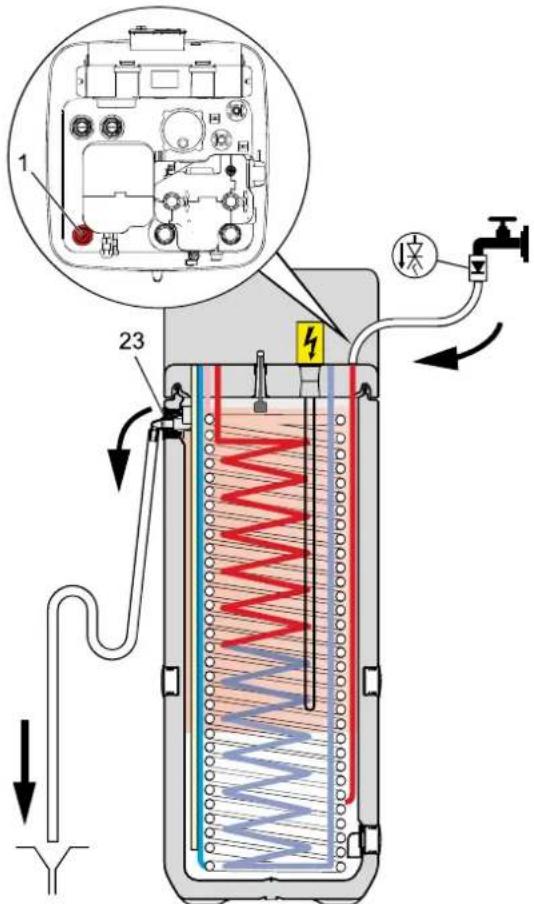
Fig. 7-1 Buffer storage filling - without solar system
7.4 Filling and topping up the heating system

DANGER!
During the filling procedure, water can leak from potential leaking sites, which, in the event of contact with live parts, can result in an electric shock.
- Disconnect the Daikin Altherma EHS(X/H) before filling.
- After the initial filling, prior to switching on the power supply to the Daikin Altherma EHS(X/H), check whether all electronic parts and connection points are dry.

WARNING!
Polluted domestic water is hazardous to health.
- When filling the heating system prevent any back-flow of heating water into the drinking water piping.

Observe the information on the water connection and water quality in accordance with chap. 2.4 and 4.4.
- Connect the filling hose (fig. 7-2, item 1) with back flush prevention (1/2") and an external pressure gauge (on-site) to the KFE cock (fig. 7-2, item 2) and secure from slipping using a hose clamp.
- Connect the drain hose to the venting valve and direct away from the unit. Open the venting valve with connected hose and check that the other venting valve is closed.
- Open the water cock (fig. 7-2, item 4) in the supply line.
- Open KFE cock (fig. 7-2, item 2) and watch the pressure gauge.
- Fill the system with water until the system target pressure is reached on the pressure gauge (System height +2 m, whereby 1 m water column = 0.1 bar). The overpressure valve must not be triggered!
- Close manual venting valve as soon as bubble-free water comes out.
- Close water stopcock (fig. 7-2, item 4). KFE valve must remain open so that the water pressure can be read off on the external pressure gauge.
- Switch on the power supply of the Daikin Altherma EHS(X/H).
- Set rotary switch to position operating mode and select "Heating".
→ Daikin Altherma EHS(X/H) runs in the hot water heating mode after the start phase. - During hot water heating mode, continuously check the water pressure on the external pressure gauge and if necessary, top up the water via the KFE valve (fig. 7-2, item 2).
7 Service and maintenance
- Vent the entire heating installation as described in chapter 5.1.4 (open the regulating valves on the installation. At the same time the underfloor heating system can be filled and flushed with the underfloor heating distributor.).
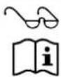
Air Purge (see operating manual of the control unit)
- Inspect the water pressure at the external pressure gauge again. Where necessary, refill with water via the KFE cock (fig. 7-2, item 2).
- Disconnect the filler hose (fig. 7-2, item 1) with flow-back preventer from the KFE cock (fig. 7-2, item. 2).
1 Filler hose
2 KFE cock
3 Ball cock
4 Water cock
5.1 Valve drive
Fig. 7-2 Filling the heating circuit
5.2 Unlocking button of the drive lock
6 Automatic bleeder
3UVB1, 3UV DHW
3-way diverter valve
8 Errors, malfunctions and messages

CAUTION!
Electrostatic charges can lead to voltage arcing that can destroy the electronic components.
- Ensure equipotential bonding before touching the switching field circuit board.
8.1 Recognising errors, correcting malfunctions
Electronic control of the Daikin Altherma EHS(X/H):
– signals an error by means of the background of the display lighting up red and shows an error code in the display (see tab. 8-2).
– shows information messages regarding the operating status, which is not signaled by red background lighting.
An integrated Protocol saves up to 15 error-related or other information messages regarding the operating status that last occurred.
Depending on the operating mode, messages are also forwarded to connected room stations or room thermostats.
8.1.1 Current fault display
1 Fault message as code (see tab. 8-2)
2 Location information (equipment) of the detected fault
3 Bus address of the unit causing the fault
Fig. 8-1 Displays an active error message (controller fault)
1 Fault message as code (see tab. 8-2)
2 Fault message as clear text (see tab. 8-2)
3 Location information (equipment) of the detected fault
4 Bus address of the unit causing the fault
Fig. 8-2 Display of a current error message (heat pump fault)
8.1.2 Read Protocol
The report can be read out in the "Special Level" (see fig. 8-3).
The last received (latest) message is in the first position. All other previous messages are then pushed backwards by one place when a new entry is made. The 15th message will be deleted any time a new message is received.
flowchart
graph TD
    A["Special Level"] --> B["Manual Operation"]
    B --> C["FA failure"]
    C --> D["Special Level"]
    D --> E["FA failure E75"]
    E --> F["Protocol"]
    F --> G["Timeprog Reset"]
    G --> H["Read Protocol"]
    H --> I["Protocol"]
    I --> J["03.01.13 E75 02.01.13 E50"]
    J --> K["03.01.13 11:16 E75 Inside Unit: Boiler Address: 0"]
    H --> L[">5 s"]
Fig. 8-3 Reading the protocol
8.1.3 Troubleshooting
Information messages, which are displayed without red backlighting, normally result in no permanent limitations on the operation of the Daikin Altherma EHS(X/H).
Messages that are displayed with an error code E.... and red back-lighting required error correction by an authorised and trained expert heating technician.
For information on warning messages see section 8.3.
• Detecting and remedying the cause of the malfunction.
- Contactor triggered:
Nothing shown on the display in the controller. Ascertain cause of triggering the contactor and remedy fault. Start up system again.
→ Once the cause has been remedied, the system will resume operations as normal.
- Contactor not triggered:
a) No fault codes are shown but the system is not working properly. Troubleshooting and eliminating faults (see section 8.2).
→ Once the cause has been eliminated, the system continues to work normally.
b) Fault codes are displayed as long as the fault conditions are present. Troubleshooting and eliminating faults (see section 8.3). If the fault message is still displayed after the cause of the fault has been corrected, the system must be disconnected from the power supply for at least 10 in order to unlock it.
→ Once the cause has been eliminated, the system continues to work normally.
8.2 Malfunctions
| Malfunction Possible cause Possible solution | ||
| System not working (nothing on the display, operation LED on RoCon BM1 off) | No mains voltage | Switch on the external main switch of the machine.Switch on system fuse(s).Replace system fuse(s). |
| Switching time program is not working or programmed switching times are being carroed out at the wrong time. | Date and time are not correctly set. | Set date.Set time.Check week day-switching time allocation. |
| Incorrect operating mode set. Set to operating model "Automatic 1" or "Automatic 2". | ||
| During a switching time the user made a manual setting (e.g. changed the target temperature, changed the operating mode) | 1. Place the rotary switch in the "Info" position.2. Place the rotary switch in the "Operating Mode" ⏻... Position.3. Select correct operating mode. | |
| Control unit does not respond to entries | Operating system of control unit crashed. | Carry out RESET of control unit. To do so, disconnect the system from the power supply for at least 10 s and then switch on again. |
| Operating data are not updated | Operating system of control unit crashed. | Carry out RESET of control unit. To do so, disconnect the system from the power supply for at least 10 s and then switch on again. |
| Heating does not warm up | Heating request switched off (e.g. switching time program is in the economy phase, external temperature is too high, parameters for Backup-Heater (EKBUxx) are set incorrectly, hot water request is active) | Check the operating mode setting.Check the request parameters.Check setting of the date, time and switching time program on the control unit. |
| Refrigerant compressor is not working. | If there is a Backup-Heater installed (EKBUxx): Check whether the return flow temperature Backup-Heater heats up to at least 15 °C (if the return flow temperature is low, the heat pump first uses the Backup-Heater in order to reach this minimum return flow temperature).Check the mains supply to the Backup-Heater (EKBUxx).Thermal protection switch (STB) on Backup-Heater (EKBUxx) has been triggered. Unlock. | |
| System is in the operating mode "Cooling". | Switch the operating mode to "Heating". | |
| Settings for off-peak mains connection do not correspond to settings for electrical connections. | HT/NT function is active and the parameter [HT/NT Contact] is set incorrectly.Other configurations are also possible. However, these must match the type of off-peak mains connection.The parameter [SMART GRID] is active and the connections are set incorrectly. | |
| The power company has sent the high-cost signal. | Wait for the repeat off-peak rate signal which reactivates the power supply. | |
| Heating does not warm up enough | Water flow too low. | Check that all stop valves of the water circuit are completely open.Check that the water filter is dirty.Check that the expansion tank is defective.Fully vent the heating system and device-internal circulation pump.On the control unit (rotary switch position "Info")check that there is sufficient water pressure (>0.5 bar), if necessary, refill the heating water.Check that the resistance in the water circuit is not too high for the pump (see installation manual for "Technical Data"). |
| Target value range is too low. | Increase parameter [Heat-Slope].Increase parameter [T vbh1 max].Increase parameter [Max T-Flow]. | |
| Weather-controlled flow temperature regulation. | Check the settings on the "HC Configuration" level of the parameters [T-Outside lim day], [Heat-Slope] and the settings in the "Set Temp Day" Military switch position. | |
| Optional Backup-Heater (EKBUxx) or alternative heater not switched on. | Check the mains supply to the Backup-Heater (EKBUxx).Thermal protection switch (STB) on Backup-Heater (EKBUxx) has been triggered. Unlock.Check the parameters [Function Heating] and [BUH s1 power] and [BUH s2 power]. | |
| Water quantity in heating system too low | Check the primary pressure in the expansion container and the water pressure, if necessary, refill the heating water and reset the primary pressure (see chapter 7.4). | |
| Hot water supply is taking too much of the output of the heat pump. | Check the settings of the parameter [Function Heating] in level "Configuration", sub-level "Setup".Check the settings of the parameter [Power DHW] in level "Configuration", sub-level "System". | |
| Hot water does not warm up | DIP switch configured incorrectly | Check DIP switch setting on board A1P (see section 8.4). |
| Hot water supply switched off (e.g. switching time program is in the economy phase, parameters for hot water supply have been set incorrectly). | Check the operating mode setting.Check the request parameters. | |
| Storage tank charging temperature too low. Increase the target hot water temperature. | ||
| Draw-off rate too high. Reduce the draw-off rate limit throughput. | ||
| Output of heat pump too low. | Check the switching times for room heating and hot water supply for overlaps. | |
| Water quantity in heating system too low. | Check the primary pressure in the expansion container and the water pressure, if necessary, refill the heating water and reset the primary pressure (see chapter 7.4). | |
| Optional Backup-Heater (EKBUxx) or alternative heater not switched on. | Check the mains supply to the Backup-Heater (EKBUxx).Thermal protection switch (STB) on Backup-Heater (EKBUxx) has been triggered. Unlock.Check the parameters [Function Heating] and [BUH s1 power] and [BUH s2 power]. | |
| Room cooler does not cool | Water flow too low. | Check that all stop valves of the water circuit are completely open.Check that the water filter is dirty.Check that the expansion tank is defective.Fully vent the heating system and device-internal circulation pump.On the control unit (rotary switch position "Info" check that there is sufficient water pressure (>0.5 bar), if necessary, refill the heating water.Check that the resistance in the water circuit is not too high for the pump (see installation manual for "Technical Data"). |
| "Cooling" switched off (e.g. room thermostat requires "Cooling", but switching time program is in economy phase, outside temperature too high). | Check the operating mode setting.Check the request parameters.Check setting of the date, time and switching time program on the control unit. | |
| Refrigerant compressor is not working. | If there is a Backup-Heater installed (EKBUxx): Check whether the return flow temperature Backup-Heater heats up to at least 15 °C (if the return flow temperature is low, the heat pump first uses the Backup-Heater in order to reach this minimum return flow temperature).Check the mains supply to the Backup-Heater (EKBUxx).Thermal protection switch (STB) on Backup-Heater (EKBUxx) has been triggered. Unlock. | |
| System is in the operating mode "Heating". Switch the operating mode to "Cooling". | ||
| Outdoor temperature < 4 °C | The heat pump has automatically switched to the "Heating" operating mode so as to be able to guarantee frost protection should the external temperature drop further. Room cooling not possible. | |
| Cooling effect of room cooling insufficient | Water flow too low. | Check that all stop valves of the water circuit are completely open.Check that the water filter is dirty.Check that the expansion tank is defective.Fully vent the heating system and device-internal circulation pump.On the control unit (rotary switch position "Info" check that there is sufficient water pressure (>0.5 bar), if necessary, refill the heating water.Check that the resistance in the water circuit is not too high for the pump (see installation manual for "TechnicalData"). |
| Water quantity in heating system too low. | Check the primary pressure in the expansion container and the water pressure, if necessary, refill the heating water and reset the primary pressure (see chapter 7.4). | |
| Quantity of coolant in the heating system too low or too high. | Determine the cause for the coolant being too low or too high in the coolant circuit.→ If the quantity of coolant is too low, check the coolant circuit for leaks, repair and top up the coolant.→ If the quantity of coolant is too great, recycle the coolant and refill the system with the correct volume. | |
| Malfunction Possible cause Possible solution | ||
| Device-internal circulation pump is excessively noisy while running | Air in the water circuit | Fully vent the heating system and device-internal circulation pump. |
| Noises caused by vibrations. | Check the Daikin Altherma EHS(X/H), its components and covers to ensure they are fastened correctly. | |
| Bearing damage in the device-internal circulation pump. | Reduce pump speed [Min Perform Pump] and [Max Perform Pump]).Replace device-internal circulation pump. | |
| Water pressure at pump inlet too low. | On the controller (rotary switch setting "Info" check whether there is adequate water pressure (>0.5 bar).Check that the pressure gauge is working correctly (connect an external pressure gauge).Check the primary pressure in the expansion container and the water pressure, if necessary, refill the heating water and reset the primary pressure (see chapter 7.4). | |
| Safety pressure relief valve is leaking or always open. | Expansion tank is defective. | Replace expansion tank. |
| Water pressure in the heating system is too high. | On the control unit (rotary switch position "Info" check that the water pressure lies beneath the stated maximum pressure. If necessary, bleed the water until the pressure lies in central permissible range. | |
| Safety pressure relief valve is stuck. | Check safety pressure relief valve and if necessary, replace it.- Turn the red knob on the safety pressure relief valve counterclockwise. If you can hear a rattling noise, the safety pressure relief valve needs replacing. | |
Tab. 8-1 Possible malfunctions of the Daikin Altherma EHS(X/H)
8.3 Fault codes

In the case of all malfunctions / error messages due to possibly defective sensors, all associated connection cables, connection points (plug contacts correctly in place) and printed circuit boards must be checked before replacing the sensor.
Component allocation: see fig. 3-1 to fig. 3-5 and fig. 8-4
| Code Malfunction / Error messages | Component/Designation | Causes and possible error correction | ||
| Display | Internal | |||
| E9001 80 | Fault T | return | Return flow temperature sensor t_R2 | Sensor or connection cable defective.Check, replace. |
| E9002 81 | Fault feed flow | Flow temperature sensor t_V1 or t_V,BH | Sensor or connection cable defective.Check, replace. | |
| E9003 89 | Frost protection function error | Plate heat exchanger (PHE) | Measured value t_V1<0 °C-Failure of the frost protection function for the plate heat exchanger because the water flow is too low. See error code E9004 / 7H.-Failure of the frost protection function of the plate heat exchanger because there is a lack of coolant in the system. See error code E9015 / E4. | |
8 Errors, malfunctions and messages
| Code Malfunction / Error messages | Component/Designation | Causes and possible error correction | ||
| Display | Internal | |||
| E9004 7H | Fault volume flow Flow sensor FLS | Water flow is too low or there is none at all. Minimum water flow required:– Operating mode "Heating": 600 l/h– Operating mode "Cooling": 840 l/h– Automatic defrosting function ( ) active: 1020 l/hCheck the following items:All stop valves of the water circuit must be completely open.Optional water filters must not be contaminated.Heating system must run within its operating range.Heating system and device-internal circulation pump must be completely bled.On the controller (rotary switch setting "Info" check whether there is adequate water pressure (>0.5 bar).Check the function of the 3-way switching valve 3UVB1 (compare actual setting of 3UVB1 with BPV position [Overview] displayed in the parameter).If this fault occurs during defrost operation in the operating mode room heating or hot water supply? With optional Backup-Heater: check its power supply and fuses.Check the fuses in the control housing of the Daikin Altherma EHS(X/H) (pump fuse (FU1) on circuit board A1P and printed circuit board fuse (F1) on the RoCon BM1 circuit board).Check flow sensor FLS for contamination and function, if necessary clean, replace. | ||
| E9005 8F | Flow temperature t_V,BH>75°C | Flow temperature sensor t_V,BH | Flow temperature of the Backup-Heater ( t_V,BH ) is too high.– Flow temperature sensor sending incorrect values. Temperature sensor or connecting cable defective.Check, replace.– Contact problem A1P-bridge on X3A. | |
| E9006 8H | Flow temperature t_V,BH>65°C | Flow temperature sensor t_V,BH | ||
| E9007 A1 IU main | board def Circuit board A1P | Board A1P | Communication between the heat pump exterior equipment and heat pump interior equipment malfunctioning.– Electromagnetic influences.Perform reset.– Circuit board A1P defective.Replace circuit board A1P. | |
| E9008 A5 | Coolant temperature outside of the valid range | Temperature sensor (liquid-side coolant) t_L2 | No heat absorption at the plate heat exchanger.Check flow.If the flow is OK, then replace the coolant temperature sensor. | |
| E9009 AA | STB faulton board A1P | Optional: STB Backup-Heater (EKBUxx) | Thermal protection switch (STB) on Backup-Heater (EKBUxx) was triggered.Replace Backup-Heater (EKBUxx). | |
| E9010 AC Bridge | Bridge of connection socket "X21A" missing on board A1P.Plug in strapping plug. | |||
| E9011 C0 Fault flow sensor Flow sensor FLS | Flow sensor FLS defective.Replace flow sensor FLS. | |||
| E9012 C4 Fault feed flow | Flow temperature sensor t_V1 or t_V,BH | Measurement outside the permitted value range. Sensor or connection cable defective.Check, replace. | ||
| E9013 E1 OU main board def | Main board of the heat pump exterior unit | – Main board in the heat pump exterior unit defective.– Ventilator motor defective.Check, replace. | ||
| E9014 | E3 Coolant | over- | High pressure switch S1PH in the coolant system | Pressure in refrigerant system is too high.- High pressure switch S1PH or ventilator motor defective. Check, replace.- Poor cable contact.- Flow in the heating system too low.- Filled coolant quantity too high. Check, replace.- Service valve in the heat pump exterior unit not open. Service valve open. |
| E9015 | E4 Coolant | under- | Pressure sensor S1NPH in the heat pump exterior unit | Pressure in the coolant system is too low.- Coolant quantity too low. Check, correct cause, refill coolant.- Pressure sensor S1NPH in the heat pump exterior unit defective.- Temperature sensor lamella heat exchanger R4T in the heat pump exterior unit defective.- Solenoid valve in the heat pump exterior unit not open.- Main board in the heat pump exterior unit defective. Check, replace. |
| E9016 | E5 Load protec comp | Electronic overload protection in the coolant compressor | Coolant compressor overload protection triggered. Pressure difference between the high and low pressure sides in the coolant circuit too high (>26 bar).- Coolant compressor defective.- Inverter board in the heat pump exterior unit defective.- Coolant compressor / inverter board cabling, poor contact.- Filled coolant quantity too high. Check, replace.- Service valve in the heat pump exterior unit not open. Service valve open. | |
| E9017 | E7 Fan blocked | Ventilator motor in the heat pump exterior unit | - A fan in the external heat pump device is blocked. Check ventilator for the effects of contamination or blockages, if necessary clean and clear blockage.- Ventilator motor defective.- Ventilator motor, poor contact.- Overvoltage at the ventilator motor.- Fuse in the heat pump exterior unit defective.- Inverter board in the heat pump exterior unit defective. Check, replace. | |
| E9018 | E9 Expansion valve | Electronic expansion valve | The electronic expansion valve in the external heat pump unit is defective, replace. | |
| E9019 | EC | Hot water temperature >85 °C | Storage tank temperature sensor t_DHW2 | The storage tank temperature sensor t_DHW2 delivers a temperature value >85 °C.Sensor or connection cable defective. Check, replace. |
| E9020 | F3 Evaporator over- | Discharge temperature sensor (hot gas sensor) R2T on the coolant compressor of the heat pump exterior unit too high | - Discharge temperature sensor R2T at the coolant compressor or connection cable defective.- Coolant compressor defective. Check, replace. | |
| E9021 | H3 HPS-System | High pressure switch S1PH in the heat pump exterior unit | - High pressure switch S1PH defective.- Main board in the heat pump exterior unit defective.- Cabling, poor contact. Check, replace. | |
8 Errors, malfunctions and messages
| Code Malfunction / Error messages | Component/Designation | Causes and possible error correction | ||
| Display | Internal | |||
| E9022 H9 | Fault A | T sensor | External temperature sensor R1T in the heat pump exterior unit | Sensor or connection cable defective. Check, replace. |
| E9023 HC | Fault D | HW sensor | Storage tank temperature sensor t_DHW2 | |
| E9024 J1 | Pressure | sensor | Pressure sensor S1NPH in the heat pump exterior unit | |
| E9025 J3 | Fault T- | return | Discharge temperature sensor R2T in the heat pump exterior unit | |
| E9026 J5 | Suction pipe sensor | Suction temperature sensor R3T in the heat pump exterior unit | ||
| E9027 J6 | Aircoil sensor Defrost | Temperature sensor of the lamella heat exchanger R5T in the heat pump exterior unit | ||
| E9028 J7 | Aircoil sensor temp | Temperature sensor of the lamella heat exchanger R4T in the heat pump exterior unit (only in 11-16 kW systems) | ||
| E9029 J8 | Fault cold sensor OU | Temperature sensor liquid-side R6T in the heat pump exterior unit | ||
| E9030 L4 | Electrical defect | Temperature sensor R10T on the inverter board in the heat pump exterior unit (only in 11-16 kW systems) | Excess temperature in the heat pump exterior unit– Very high external temperature.– Insufficient cooling of the inverter board.– Air suction inlet contaminated / blocked.– Inverter board in the heat pump exterior unit defective.– Temperature sensor on inverter board defective, plug connection X111A not correct.• Check, correct cause, replace.• If necessary contact Daikin service technician. | |
| E9031 L5 | Overvoltage error in electrical components | a) If the fault <15x occurs, the functional safety of the Daikin Altherma EHS(X/H) still remains.→ Sporadic message during the continuous self-monitoring of the unit.• No additional measures are required.b) If the fault arises 15x, it acts as a lock and can have the following causes:– Current mains overvoltage.– Coolant compressor blocked or defective.– Inverter board in the heat pump exterior unit defective.– Cabling, poor contact.– Service valve in the heat pump exterior unit not open.• Check, correct cause, replace.• If necessary contact Daikin service technician. | ||
| E9032 L3 | Electrical components | – Coolant compressor defective.– Inverter board in the heat pump exterior unit defective.• Check, replace.• If necessary contact Daikin service technician. | ||
| E9033 L9 | – Coolant compressor blocked or defective.– Before starting the coolant compressor, pressure difference between the high and low pressure sides too high.– Service valve in the heat pump exterior unit not open.• Check, correct cause, replace.• If necessary contact Daikin service technician. | |||
| E9034 LC | Communication error - Internal communication in the heat pump exterior unit disrupted– Electromagnetic influences.• Perform reset.– Main board in the heat pump exterior unit defective.– Inverter board in the heat pump exterior unit defective.– Ventilator motor defective.– Cabling, poor contact.• Check, correct cause, replace.• If necessary contact Daikin service technician. | |||
| E9035 P1 | OU ma | n board def | Inverter board in the heat pump exterior unit | – No supply voltage from the mains connection.– Inverter board in the heat pump exterior unit defective.• Check, correct cause, replace.• If necessary contact Daikin service technician. |
| E9036 P4 | Electrical defect | Temperature sensor R10T on the inverter board in the heat pump exterior unit (only in 11-16 kW systems) | Excess temperature in the heat pump exterior unit– Inverter board in the heat pump exterior unit defective.– Temperature sensor on inverter board defective, plug connection X111A not correct.• Check, correct cause, replace.• If necessary contact Daikin service technician. | |
| E9037 P | J Setting | output | Power setting for the heat pump exterior unit incorrect | • Contact a Daikin service technician. |
8 Errors, malfunctions and messages
| Code Malfunction / Error messages | Component/Designation | Causes and possible error correction | ||
| Display | Internal | |||
| E9038 U0 | Coolant | leak | Sensors and parameter settings in the heat pump exterior unit | Loss of coolant.- Coolant quantity too low. See error code E9015 / E4.- Block or leak in the coolant line.• Check, correct cause, refill coolant. |
| E9039 U2 | Under/over voltage | Mains voltage outside the permitted ragne-Sporadic errors shortly after a power outage.No error correction required-Inverter board in the heat pump exterior unit defective.Check, replace.If necessary contact Daikin service technician. | ||
| E9041 U4 | Transmission fault | Electrical components | Communication between the heat pump exterior equipment and heat pump interior equipment malfunctioning.- Cabling or connections, poor contact.- No heat pump exterior unit connected.- Circuit board A1P defective.- Main board in the heat pump exterior unit defective.Check, replace. | |
| E9042 U5 | Communication between switch board A1P and RoCon BM1 disrupted.See error code E200. | |||
| E9043 U7 | Communication between main board and inverter board disrupted.- Main board in the heat pump exterior unit defective.- Inverter board in the heat pump exterior unit defective.- Cabling, poor contact.Check, correct cause, replace. | |||
| E9044 UA | Configuration of switchboard A1P not suitable for the heat pump exterior unitReplace circuit board A1P.If necessary contact Daikin service technician. | |||
| E75- | Error in external temperature sensor | External temperature sensor t_AU (RoCon OT1) | Optional external temperature sensor RoCon OT1 defective or not connected.Check, replace.If there is no external temperature sensor connected, check the parameter [Outside Config] configuration. | |
| E76- | Error storage tank temperature sensor | Storage tank temperature sensor t_DHW1 | Storage temperature sensor t_DHW1 or connection cable defective or not connected.Check, replace.Check configuration [Storage Config]. | |
| E81- | Communicationfor RoCon BM1CAN modules Bus | Circuit board RoCon BM1 | Parameter store in EEPROM faulty.Contact a Daikin service technician. | |
| E88-Circuit board | Connected | Parameter store in external flash memory faulty.Contact a Daikin service technician. | ||
| E91- | D of a CAN module duplicated | ted, set unique data bus address. | ||
| E128- | Error return flow temperature sensor | Return flow temperature sensor t_R1 | Return flow temperature sensor t_R1 in the flow sensor FLS or connection cable defective.Check, replace. | |
| E129- | Pressure sensor error | Pressure sensor DS | Pressure sensor DS defective.Check, replace. | |
| Code Malfunction / Error messages | Component/Designation | Causes and possible error correction | ||
| Display | Internal | |||
| E198 — | Flow measurement not plausible | Flow sensor FLS, 3-way diverter valve 3UVB1 | Error occurs if the 3-way diverter valve 3UVB1 is in the Bypass position, the device-internal circulation pump is running, but the volumetric flow measurement is too low.Minimum water flow required:– Operating mode "Heating": 600 l/h– Operating mode "Cooling": 840 l/h– Automatic defrosting function ( ) active: 1020 l/h– Air in heating system.● Vent.– Device-internal circulation pump not running.● Check electrical connection and control settings. If the circulation pump is defective, replace it.– Flow sensor FLS contaminated, blocked.● Check, clean.– Flow sensor FLS defective.– Valve drive for 3-way diverter valve 3UVB1 defective.● Check, replace. | |
| E200 — | Communication fault | Electrical components | Communication between RoCon BM1 and switchboard A1P is disrupted.– Cabling or connections, poor contact.● Check, replace | |
| E8005 — | Water pressure in the heating system too low | Pressure sensor DS | Water pressure has fallen below the minimum permissible value.– Too little water in the heating system.● Check heating system for leakage, refill water.– Pressure sensor DS defective.● Check, replace. | |
| E8100 — | Communication Electrical components | Initialisation also failed after heat pump start-up.Circuit board A1P defective.● Check, replace. | ||
| E9000 — | Temporary internal message | — | Not relevant to proper system operation. | |
| W8006 — | Pressure loss warning | Pressure sensor DS | Warning message: Maximum permissible pressure drop exceeded.Too little water in the heating system.● Check heating system for leakage, refill water. | |
| W8007 — | Water pressure in the heating system too high | Warning message: Water pressure has exceeded the maximum permissible value.– Membrane expansion vessel defective or incorrect pressure set.● Check, replace.– Setting for the[Max Pressure] parameter too low.● If necessary, set parameter. If setting correct,→ Drain water to reduce the system pressure. | ||
Tab. 8-2 Error codes on the main control unit of Daikin Altherma EHS(X/H)

Respect the maximum tightening torque of the temperature sensor (see section 10.3 "Tightening torque").
flowchart
graph TD
    A["Plant"] --> B["R1T"]
    B --> C["R5T"]
    C --> D["c"]
    D --> E["R4T"]
    E --> F["b"]
    F --> G["e"]
    G --> H["f"]
    H --> I["e"]
    I --> J["R6T"]
    J --> K["g"]
    K --> L["a"]
    L --> M["Control Unit"]
    M --> N["S1PH"]
    M --> O["R2T"]
    M --> P["k"]
    M --> Q["S1NPH"]
    M --> R["i"]
    M --> S["R3T"]
    M --> T["h"]
    M --> U["o"]
    M --> V["R10T"]
Fig. 8-4 Components in the heat pump circuit (simplified diagram)
a Plate heat exchanger (condensator)
b Ventilator motor
c Lamella heat exchanger (evaporator)
e Filter
f Electronic expansion valve
g Service valve (liquid line)
h Service valve with maintenance connection (gas line)
i Accumulator
k Coolant compressor
n 4-way diverter valve (—> Heat, ⋯> Cool)
o Inverter board
R1T External temperature sensor
R2T Discharge temperature sensor (coolant compressor)
R3T* Suction temperature sensor (coolant compressor)
R4T* Temperature sensor lamella heat exchanger-input
R5T Temperature sensor lamella heat exchanger-middle
R6T* Temperature sensor liquid line (t L2)
R10T* Temperature sensor on inverter board
S1PH High pressure switch
S1NPH Pressure sensor
* Only with 11-16 kW heat pump external devices.
Tab. 8-3 Legend for fig. 8-4
8.4 Monitoring and configuration DIP Switch

WARNING!
Touching live parts can result in an electric shock and lead to potentially fatal injuries and burns.
- Before beginning work on live parts, disconnect all of the systems circuits from the power supply (switch off main switch, disconnect fuse) and secure against unintentional restart. Means with contact separation in all poles that provide full disconnection must be incorporated in the fixed wiring in accordance with the wiring rules.
- Disconnect the system from the power supply.
- Open the control housing and remove the RoCon BM1 board (see chapter 4.5.7).
- Check the DIP switch setting on the A1P circuit board of the Daikin Altherma EHS(X/H), adjust where necessary (see tab. 8-4).
The factory preset may only be changed if e.g. an optional accessory was connected. - Replace the RoCon BM1 switch board, close the control housing and reconnect the power supply.

DIP switch settings are not recognised until a brief interruption to the power supply.
Fig. 8-5 Setting of DIP switch SS2
| DIP switch | No. | Designation | Factory setting |
| SS2 | 1 | Do not change. | OFF |
| 2 | Domestic hot water generation | ON | |
| 3 | Pump continuous running* | OFF | |
| 4 | Do not change. | OFF |
* If you intend to run the internal heating circulation pump continuously, it will need to be connected to the circuit board A1P, plug X17A, via a separate connection cable (E1400132).
Tab. 8-4 DIP switch settings
8.5 Emergency operation
In the case of incorrect setting in the electronic control system, emergency heating operation can be maintained by activating the special "Manual Operation" function on the control unit (see operating manual for the control unit).
If the 3-way valves are intact, the Daikin Altherma EHS(X/H) switches to Heating mode. The necessary flow temperature can be adjusted with the rotary switch.
9 Hydraulic system connection

WARNING!
High temperatures can occur in the solar storage tank. Therefore, sufficient scalding protection must be included when the hot water system is installed (automatic hot water mixing device).

The Daikin units can also be optionally fitted with gravity breaks made of plastic to prevent thermal losses caused by gravity flow. These are suitable for operating temperatures of maximum 95 °C and for fitting in all tank-side heat exchanger connections (except heat exchangers for pressurised solar tank charging).
The customer must install suitable circulation brakes for components connected to the heat exchanger for pressurised solar tank charging.

A selection of diagrams of the most common systems is shown below. The arrangements shown are only examples, and are no substitute for careful system planning. For more diagrams and further information about the electrical connection please see the Daikin homepage.
flowchart
graph TD
    A["EHS157068"] --> B["MIX"]
    B --> C["PMI"]
    C --> D["H2"]
    D --> E["H1"]
    E --> F["MK1/MK2"]
    F --> G["SAS1"]
    G --> H["PWT"]
    H --> I["P"]
    I --> J["3UVB1"]
    J --> K["3UV DHW"]
    K --> L["EKBUxx"]
    L --> M["RoCon HP"]
    M --> N["EKSRPS4A"]
    N --> O["Altherma EHS(X/H)"]
    P["DHW"] --> Q["VS"]
    Q --> R["Pz"]
    R --> S["7a"]
    S --> T["7"]
    T --> U["tDHW"]
    U --> V["Ts"]
    V --> W["1"]
    W --> X["TR"]
    X --> Y["Ps"]
    Y --> Z["Sw"]
    Z --> AA["CV"]
    AA --> AB["SW"]
    AB --> AC["C"]
    AC --> AD["V"]
    AD --> AE["ERLQ"]
    AE --> AF["10"]
    AF --> AG["9"]
    AG --> AH["1"]
    AH --> AI["2"]
    AI --> AJ["6"]
    AJ --> AK["DHW"]
    AK --> AL["SW"]
    AL --> AM["SV"]
    AM --> AN["10"]
    AN --> AO["9"]
    AO --> AP["10"]
Fig. 9-1 Daikin Altherma EHS(X/H) (afll types) with DrainBack Solar (for legend see tab. 9-1)
flowchart
graph TD
    A["ERLQ"] --> B["EHS157068"]
    B --> C["MIX"]
    C --> D["H2"]
    D --> E["H1"]
    E --> F["SAS1"]
    F --> G["t_AU"]
    G --> H["3UVB1"]
    H --> I["3UV DHW"]
    I --> J["EKBUxx"]
    J --> K["RoCon HP"]
    K --> L["t_DHW"]
    L --> M["Altherma EHS(X/H)"]
    M --> N["SAK2"]
    N --> O["P_W2"]
    O --> P["RPWT1"]
    P --> Q["TMV"]
    Q --> R["P_W1"]
    R --> S["W_EX max: 8kW"]
    T["DHW"] --> U["Pz"]
    U --> V["VS"]
    V --> W["7a"]
    W --> X["7a"]
    X --> Y["1"]
    Y --> Z["SV"]
    Z --> AA["CW"]
    AA --> AB["T"]
    AB --> AC["7"]
    AC --> AD["10"]
    AD --> AE["9"]
    AE --> AF["2"]
    AF --> AG["6"]
    AG --> AH["2"]
    AH --> AI["7a"]
    AI --> AJ["1"]
    AJ --> AK["2"]
    AK --> AL["7a"]
    AL --> AM["10"]
    AM --> AN["9"]
    AN --> AO["2"]
    AO --> AP["7a"]
    AP --> AQ["10"]
Fig. 9-2 Daikin Altherma EHS(X/H)..P50B with wood-burning boiler < 8 kW without solar support (for legend, see tab. 9-1)
flowchart
graph TD
    A["ERLQ"] --> B["EHS157068"]
    B --> C["MIX"]
    C --> D["PIMI"]
    D --> E["H2"]
    E --> F["H1"]
    F --> G["FLS"]
    G --> H["Tv"]
    H --> I["SK"]
    I --> J["Tk"]
    J --> K["TK"]
    K --> L["tAu"]
    M["DHW"] --> N["VS"]
    N --> O["PWT"]
    O --> P["P"]
    P --> Q["3UVB1"]
    P --> R["3UV DHW"]
    P --> S["EKBUxx"]
    P --> T["RoCon HP"]
    U["C"] --> V["V"]
    V --> W["E"]
    W --> X["ERLQ"]
    Y["SW"] --> Z["SV"]
    AA["TS"] --> AB["Altherma EHS(X/H)B"]
    AC["Pz"] --> AD["7"]
    AD --> AE["7"]
    AE --> AF["1"]
    AG["Ps"] --> AH["TR"]
    AH --> AI["SAK2"]
    AI --> AJ["MAG"]
    AJ --> AK["≤85°C"]
    AK --> AL["TMV"]
    AL --> AM["Pw1"]
    AM --> AN["WEX max: 8kW"]
    AO["tAU"] --> AP["10"]
    AP --> AQ["9"]
    AQ --> AR["4 3"]
    AR --> AS["SAS1"]
    AS --> AT["MAG"]
    AT --> AU["10"]
    AU --> AV["9"]
    AW["TL"] --> AX["2"]
    AY["TL"] --> AZ["6"]
    BA["TL"] --> BB["7"]
Fig. 9-3 Daikin Altherma EHS(X/H) B..P50B with wood-burning boiler < 8 kW and DrainBack solar p=0 (for legend see tab. 9-1)
| Short name. | Meaning |
| 1 Cold water distribution network | |
| 2 Hot water distribution network | |
| 3 Heating flow | |
| 4 Heating return flow | |
| 5 Mixer circuit (optional) | |
| 6 Circulation (optional) | |
| 7 Check valve, return valve | |
| 7a Non return valves | |
| 8 Solar circuit | |
| 9 Gas pipe (coolant) | |
| 10 Fluid pipe (coolant) | |
| 3UVB1 | 3-way diverter valve (internal heat generation circuit) |
| 3UV DHW 3 way diverter valve (hot water/heating) | |
| EKBUxx Backup-Heater | |
| BV Bypass valve | |
| C Coolant compressor | |
| CW Cold water | |
| DHW Domestic hot water | |
| E Expansion valve | |
| FLG FlowGuard regulating valve with flow indicator | |
| FLS | FlowSensor - solar flow and feed flow temperature measurement |
| H_1,H_2 H_m | Heating circuits |
| MAG Diaphragm expansion vessel | |
| MIX 3-way-mixer with drive motor | |
| MK1 Mixer group with high-efficiency pump | |
| MK2 | Mixer group with high-efficiency pump (PWM controlled) |
| P_Mi | Mixing circuit pump |
| P_S | Solar operating pump p=0 |
| P_W1 | Primary circuit pump W_EX |
| P_W2 | Secondary circuit pump W_EX |
| P_Z | Circulation pump |
| PWT | Panel heat exchanger (condenser) |
| RoCon HP | Control unit for Daikin Altherma EHS(X/H) |
| EHS157068 | Mixer circuit control |
| EKSRPS4A | Solar regulating and pump unit p=0 |
| RPWT1 | Plate heat exchanger |
| ERLQ | Exterior heat pump unit |
| SAK2 | Storage tank connection (wood boiler) |
| SAS1 | Sludge and magnetic separator |
| SK Solar panel field | |
| SV Safety over-pressure valve | |
| t_AU | Outside temperature sensorRoCon OT1 (see chapter 4.5.9) |
| t_DHW | Storage tank temperature sensor (heat generator) |
| t_Mi | Mixer circuit flow temperature sensor |
| T_K | Solar collector temperature sensor |
| T_R | Solar return flow temperature sensor |
| T_S | Solar storage cylinder temp. sensor |
| Short name. | Meaning |
| T_V | Solar flow temperature sensor |
| TMV | Thermostatic 3-way valve for return temperature increase |
| V Fan (vaporiser) | |
| VS Protection | against scaldingVTA32 |
| W_EX | External heat generator |
Tab. 9-1 Short names in hydraulic drawings
10 Technical data
10.1 Equipment data
10.1.1 Daikin Altherma EHS(X/H)...P30B
| Type Daikin Altherma EHS(X/H) | 04P30B 08 | P30B B04P30B | B08P30B | |||
| Can be used with an external heat pump unit | ERLQ004CAV3 | ERLQ006CAV3/ERLQ008CAV3 | ERLQ004CAV3 | ERLQ006CAV3/ERLQ008CAV3 | ||
| Dimensions and weights Unit | ||||||
| Dimensions (H x W x D) cm 180 x 61.5 x 59.5 | ||||||
| Empty weight kg 84 89 | ||||||
| Main components | ||||||
| Water heat circula-tion pump | Type | — | Grundfos UPM3K 25-75 CHBL RT | |||
| Speed rates | — | Continuously variable (PWM) | ||||
| Voltage | V | 230 | ||||
| Frequency | Hz | 50 | ||||
| Protection type | — | IP 42 | ||||
| Maximum rated output | W | 45 | ||||
| Heat exchanger (water/coolant) | Type | — | Stainless steel underfloor heat exchanger | |||
| Heat insulation — | EPP | |||||
| Storage tank | ||||||
| Total storage capacity | litres | 294 | ||||
| Maximum permissible storage water temperature | °C | 85 | ||||
| Heat consumption at stand-by and at 60°C | kWh/24h | 1.3 | ||||
| Domestic water heat exchanger (stainless steel 1.4404) | Water capacity heat exchanger | litres | 27.1 | |||
| Maximum operating pressure | bar | 6 | ||||
| Domestic water heat exchanger sur-face | m2 | 5.8 | ||||
| Storage tank charging heat exchanger (stainless steel 1.4404) | Water capacity heat exchanger | litres | 13.2 | |||
| Heat exchanger surface area | m2 | 2.7 | ||||
| Pressurised solar heat exchanger (stainless steel 1.4404) | Water capacity heat exchanger | litres | — | 4.2 | ||
| Heat exchanger surface area | m2 | — | 0.8 | |||
| Thermal performance data1) | Hot water quantity without re-heating at a flow rate of 8 l/min (12 l/min) (TS=50°C) | litres | 184 (153) | |||
| Hot water quantity without re-heating at a flow rate of 8 l/min (TS=60°C) | litres | 282 (252) | ||||
| Hot water quantity without re-heating at a flow rate of 8 l/min (12 l/min) (TS=65°C) | litres | 352 (321) | ||||
| Re-heating rime with a draw-off quantity of:140 l = 5820 Wh (∅ bathtub)90 l = 3660 Wh (∅ shower draw-off quantity) | min | 9055 | 4530 | 9055 | 4530 | |
| Pipe connections | Cold and hot water | inches | 1" AG | |||
| Heating feed and return flow | inches | 1" IG | ||||
| Solar connections | p=0 | inches | 1" IG | |||
| +p | inches | — | 3/4" IG + 1" AG | |||
| Type | Daikin Altherma EHS(X/H) | ||||||
| 04P30B | 08P30B | B04P30B | B08P30B | ||||
| Refrigerant circuit | |||||||
| Number of circuits — 1 | |||||||
| Pipe connections | Number — 2 | ||||||
| Liquid line | Type — Flanged connection | ||||||
| External ∅ inches 1/4" AG | |||||||
| Gas lines | Type — Flanged connection | ||||||
| External ∅ inches 5/8" AG | |||||||
| Operating data | |||||||
| Operating range | Flow temperature for room heating/cooling function | Heating (min./max.) | °C | 15 to 55 | |||
| Cooling (min/max) | °C 5 to 22 | ||||||
| Hot water generation (with EKBUxx) | Heating (min./max.) | °C 25 to 80 | |||||
| Noise level | Audibility dBA 39 | ||||||
| Noise pressure 2) | dBA 28 | ||||||
| Electrical data: | |||||||
| Voltage supply | Phases — 1 | ||||||
| Voltage V 230 | |||||||
| Voltage range V | Voltage ±10% | ||||||
| Frequency | Hz 50 | ||||||
| Mains connection 3) | Daikin Altherma EHS(X/H) Circuit board RoCon BM1 | — | 3G | ||||
| Communication in the heat pump exterior unit -< > Daikin Altherma EHS(X/H), Switch board A1P | — | 3G | |||||
| External unit for heat pump | — 3G | ||||||
| Optional auxiliary heating | Backup-Heater (EKBUxx) | — | 3G (1-phase) / 5G (3-phase) | ||||
| Type | Daikin Altherma EHS(X/H) | ||||
| 04P30B | 08P30B | B04P30B | B08P30B | ||
| Performance data | |||||
| Type exterior heat pump unit | ERLQ004CAV3 | ERLQ006CAV3/ERLQ008CAV3 | ERLQ004CAV3 | ERLQ006CAV3/ERLQ008CAV3 | |
| Nominal heat output A-7/W35 kW 4.26 5.14 / 5.53 4.26 5.14 / 5.53 | |||||
| Nominal heat output A2/W35 kW 3.47 4.6 / 5.51 3.47 4.6 / 5.51 | |||||
| Nominal heat output A7/W35 kW 4.53 6.06 / 7.78 4.53 6.06 / 7.78 | |||||
| Nominal heat output A10/W35 kW 5.2 6.6 / 8.4 5.2 6.6 / 8.4 | |||||
| Nominal cooling output A35/W18 4.42 5.22 / 5.22 4.42 5.22 / 5.22 | |||||
| Nominal cooling output A35/W7 4.03 4.64 / 4.64 4.03 4.64 / 4.64 | |||||
| Nominal COP A-7/W35 2.85 2.73 / 2.78 2.85 2.73 / 2.78 | |||||
| Nominal COP A2/W35 4.07 3.64 / 3.54 4.07 3.64 / 3.54 | |||||
| Nominal COP A7/W35 5.23 4.65 / 4.6 5.23 4.65 / 4.6 | |||||
| Nominal COP A10/W35 5.53 4.95 / 4.9 5.53 4.95 / 4.9 | |||||
| Nominal EER A35/W18 21 3.65 / 3.65 4.21 3.65 / 3.65 | |||||
| Nominal EER A35/W7 | 2.85 2.51 | / 2.51 2.85 2.51 | / 2.51 | ||
| Max. heating output A-7/W35 | kW 4.6 | 5.3 / 6.4 4.6 5.3 / 6.4 | |||
| Max. heat output A2/W35 | kW 4.8 | 6.4 / 7.7 4.8 6.4 / 7.7 | |||
| Max. heat output A7/W35 | kW | 5.1 | 8.4 / 10.2 | 5.1 | 8.4 / 10.2 |
| Max. heat output A10/W35 | kW | 5.2 | 8.8 / 10.5 | 5.2 | 8.8 / 10.5 |
| Max. cooling output A35/W18 5.9 7.3 / 8.4 5.9 7.3 / 8.4 | |||||
| Max. cooling output A35/W7 4.5 5.5 / 6.4 4.5 5.5 / 6.4 | |||||
1) T_CW Cold water input temperature = 10^
T_DHW Hot water draw-off temperature = 40°C
T_S Storage target temperature (charge state before drawing off)
2) With a reference spacing of 1 m.
3) Number of individual wires in the connection cable, including protective earth. The cross-section of the individual lines is dependent on the current load, the length of the connection cable and the respective legal provisions.
Tab. 10-1 Basic data Daikin Altherma EHS(X/H)...P30B
10.1.2 Daikin Altherma EHS(X/H)...P50B
| Type Daikin Altherma EHS(X/H) | 08P50B 16P50B B08P50B B16P50B | |||||
| Can be used with an external heat pump unit | ERLQ006CAV3/ERLQ008CAV3 | ERLQ011CA(V3/W1)*/ERLQ014CA(V3/W1)*/ERLQ016CA(V3/W1)* | ERLQ006CAV3/ERLQ008CAV3 | ERLQ011CA(V3/W1)*/ERLQ014CA(V3/W1)*/ERLQ016CA(V3/W1)* | ||
| Dimensions and weights Unit | ||||||
| Dimensions (H x W x D) cm 180 x 79 x 79 | ||||||
| Empty weight kg 111 116 113 118 | ||||||
| Main components | ||||||
| Water heat circulation pump | Type — Grundfos UPM3K 25-75 CHBL RT | |||||
| Speed rates | — | Continuously variable (PWM) | ||||
| Voltage | V | 230 | ||||
| Frequency | Hz | 50 | ||||
| Protection type | — | IP 42 | ||||
| Maximum rated output | W | 45 | ||||
| Heat exchanger(water/coolant) | Type — Stainless steel underfloor heat exchanger | |||||
| Heat insulation | — | EPP | ||||
| Storage tank | ||||||
| Total storage capacity | litres | 477 | ||||
| Maximum permissible storage water temperature | °C | 85 | ||||
| Heat consumption at stand-by and at 60°C | kWh/24h | 1.4 | ||||
| Domestic water heat exchanger(stainless steel 1.4404) | Water capacity heat exchanger | litres | 29 | |||
| Maximum operating pressure bar | 6 | |||||
| Domestic water heat exchangersurface | m2 | 6,0 | ||||
| Storage tank charging heat exchanger(stainlesssteel 1.4404) | Water capacity heat exchanger | litres | 12.1 | 17.4 | 12.1 | 17.4 |
| Heat exchanger surface area | m2 | 2.5 | 3.5 | 2.5 | 3.5 | |
| Pressurised solar heat exchanger(stainlesssteel 1.4404) | Water capacity heat exchanger | litres | — | 9.3 | ||
| Heat exchanger surface area | m2 | — | 1.7 | |||
| Thermal performance data1) | Hot water quantity without re-heating at a flow rate of 8 l/min(12 l/min) (TS=50°C) | litres | 364 (318)328 4)(276 4)) | 324 (282)288 4)(240 4)) | ||
| Hot water quantity without re-heating at a flow rate of 8 l/min(TS=60°C) | litres | 540 (494) | 492 (444) | |||
| Hot water quantity without re-heating at a flow rate of 8 l/min(12 l/min) (TS=65°C) | litres | 612 (564) | 560 (516) | |||
| Re-heating rime with a draw-offquantity of:140 l = 5820 Wh (∅ bathtub)90 l = 3660 Wh (∅ shower draw-offquantity) | min | 4530 | 2517 | 4530 | 2517 | |
| Pipe connections | Cold and hot water | inches | 1" AG | |||
| Heating feed and return flow | inches | 1" IG | ||||
| Solar connections | p=0 | inches | 1" IG | |||
| +p+ | inches | — | 3/4" IG + 1" AG | |||
| Type | Daikin Altherma EHS(X/H) | ||||||
| 08P50B | 16P50B | B08P50B | B16P50B | ||||
| Refrigerant circuit | |||||||
| Number of circuits — 1 | |||||||
| Pipe connections | Number — 2 | ||||||
| Liquid line | Type — Flanged connection | ||||||
| External ∅ inches 1/4" AG 3/8" AG 1/4" | AG 3/8" AG | ||||||
| Gas lines | Type — Flanged connection | ||||||
| External ∅ inches 5/8" AG | |||||||
| Operating data | |||||||
| Operating range | Flow temperature for room heating/cooling function | Heating (min/max) | °C | 15 to 55 | |||
| Cooling (min/max) | °C 5 to 22 | ||||||
| Hot water generation (with EKBUxx) | Heating (min/max) | °C 25 to 80 | |||||
| Noise level | Audibility dBA 39 | ||||||
| Noise pressure 2) | dBA | 28 | 32 | 28 | 32 | ||
| Electrical data: | |||||||
| Voltage supply | Phases — 1 | ||||||
| Voltage | V | 230 | |||||
| Voltage range | V | Voltage ±10% | |||||
| Frequency | Hz | 50 | |||||
| Mains connection 3) | Daikin Altherma EHS(X/H) Circuit board RoCon BM1 | — | 3G | ||||
| Communication in the heat pump exterior unit -< > Daikin Altherma EHS(X/H), Switch board A1P | — | 3G | |||||
| External unit for heat pump | — | 3G | 3G (ERLQ...V3) / 5G (ERLQ...W1) | 3G | 3G (ERLQ...V3) / 5G (ERLQ...W1) | ||
| Optional auxiliary heating | Backup-Heater (EKBUxx) | — | 3G (1-phase) / 5G (3-phase) | ||||
| Performance data | |||||||
| Type exterior heat pump unit | ERLQ006CAV3/ ERLQ008CAV3 | ERLQ011CA (V3/W1)*/ ERLQ014CA (V3/W1)*/ ERLQ016CA (V3/W1)* | ERLQ006CAV3/ ERLQ008CAV3 | ERLQ011CA (V3/W1)*/ ERLQ014CA (V3/W1)*/ ERLQ016CA (V3/W1)* | |||
| Nominal heat output A-7/W35 | kW | 5.29 / 5.53 | 6 / 8.3 / 8 | 5.29 / 5.53 | 6 / 8.3 / 8 | ||
| Nominal heat output A2/W35 | kW | 4.6 / 5.51 | 7.7 / 9.6 / 10.1 | 4.6 / 5.51 | 7.7 / 9.6 / 10.1 | ||
| Nominal heat output A7/W35 | kW | 6.06 / 7.78 | 11.8 / 14.8 / 15.3 | 6.06 / 7.78 | 11.8 / 14.8 / 15.3 | ||
| Nominal heat output A10/W35 kW | 6.6 / 8.4 | 11.5 / 14.5 / 16.1 | 6.6 / 8.4 11.5 | 14.5 / 16.1 | |||
| Nominal cooling output A35/W18 3 | kW | 5.22 / 5.22 | 10.6 / 10.6 / 10.6 | 5.22 / 5.22 | 10.6 / 10.6 / 10.6 | ||
| Nominal cooling output A35/W7 3 | kW | 4.46 / 4.64 | 11.7 / 12.6 / 13.1 | 4.46 / 4.64 | 11.7 / 12.6 / 13.1 | ||
| Nominal COP A-7/W35 | 2.73 / 2.78 | 2.45 / 2.58 / 2.44 | 2.73 / 2.78 | 2.45 / 2.58 / 2.44 | |||
| Nominal COP A2/W35 | 3.64 / 3.54 | 3.29 / 3.22 / 3.15 | 3.64 / 3.54 | 3.29 / 3.22 / 3.15 | |||
| Nominal COP A7/W35 | 4.65 / 4.6 | 4.38 / 4.27 / 4.1 | 4.65 / 4.6 4.38 | 4.27 / 4.1 | |||
| Nominal COP A10/W35 | 4.95 / 4.9 | 4.6 / 4.41 / 4.31 | 4.95 / 4.9 4.6 | 4.41 / 4.31 | |||
| Nominal EER A35/W18 3 | 3.65 / 3.65 | 3.9 / 3.9 / 3.9 | 3.65 / 3.65 | 3.9 / 3.9 / 3.9 | |||
| Nominal EER A35/W7 3 | 2.51 / 2.51 | 2.72 / 2.47 / 2.29 | 2.51 / 2.51 | 2.72 / 2.47 / 2.29 | |||
| Max. heating output A-7/W35 | kW | 5.3 / 6.4 | 8.8 / 11.7 / 12.3 | 5.3 / 6.4 | 8.8 / 11.7 / 12.3 | ||
| Max. heat output A2/W35 | kW | 6.4 / 7.7 | 9.1 / 10.9 / 11.4 | 6.4 / 7.7 | 9.1 / 10.9 / 11.4 | ||
| Type | Daikin Altherma EHS(X/H) | ||||
| 08P50B | 16P50B | B08P50B | B16P50B | ||
| Max. heat output A7/W35 kW | 8.4 / 10.2 11.4 | / 14.6 / 16.1 8.4 / | 10.2 11.4 / 14.6 / | 16.1 | |
| Max. heat output A10/W35 kW | 8.8 / 10.5 11.9 | / 15 / 16.5 8.8 / 10.5 | 11.9 / 15 / 16.5 | ||
| Max. cooling output A35/W18 W | 7.3 / 8.4 10.6 | / 10.6 / 10.6 7.3 / | 8.4 10.6 / 10.6 / 10.6 | ||
| Max. cooling output A35/W7 W | 5.5 / 6.4 11.7 | / 12.6 / 13.1 5.5 / | 6.4 11.7 / 12.6 / 13.1 | ||
* Not all the equipment mentioned here is offered in some countries because of the various different country-specific connection conditions.
1) T_CW Cold water input temperature = 10°C T_DHW Hot water draw-off temperature = 40°C T_S Storage target temperature (charge state before drawing off)
2) With a reference spacing of 1 m.
Number of individual wires in the connection cable, including protective earth. The cross-section of the individual lines is dependent on the current load, the length of the connection cable and the respective legal provisions.
Hot water storage tank only to be charged using a heat pump, without a Backup-Heater.
Tab. 10-2 Basic data Daikin Altherma EHS(X/H)...P50B
10.2 Characteristic lines
10.2.1 Sensor characteristic lines
| Temperature sensor | ||||||||||||||||
| Measured temperature in °C | ||||||||||||||||
| -20 | -10 | 0 | 10 | 20 | 30 | 40 | 50 | 60 | 70 | 80 | 90 | 100 | 110 | 120 | ||
| Sensor resistance in kOhm according to standard or manufacturer's indications | ||||||||||||||||
| t_DHW2 | NTC | — | — | 811.5 | 480.6 | 293.2 | 183.8 | 118.2 | 77.7 | 52.3 | 35.8 | 25.1 | 17.8 | 12.9 | 9.5 | 7.1 |
| t_Au (RoCon OT1), t_DHW1 | NTC | 98.66 | 56.25 | 33.21 | 20.24 | 12.71 | 8.20 | 5.42 | 3.66 | 2.53 | 1.78 | 1.28 | 0.93 | 0.69 | 0.52 | 0,36 |
| t_Au (R1T) | NTC | 197,8 | 112,0 | 65,8 | 40.0 | 25.0 | 16.1 | 10.6 | 7.2 | 5.0 | 3.5 | 2.5 | — — | — | — | |
| t_V1, t_V,BH, t_R2 | NTC | 197.80 | 120.00 | 65.84 | 39.91 | 24.95 | 16.04 | 10.58 | 7.14 | 4.77 | 3,19 | 2.36 | 1.74 | 1.33 | 1.07 | 0.84 |
| FLS Sensor (Flow/Temperature) | ||||||||||
| FLS (t_R1/V1) | V1 | Measured flow in l/min | ||||||||
| 10.0 | 20.0 | 30.0 | 40.0 | 50.0 | 60.0 | 70.0 | 80.0 | — | ||
| Sensor output frequency in Hz | ||||||||||
| (14 - 229 Hz) | 28 | 54 | 81 | 108 | 135 | 162 | 188 | 215 | — | |
| t_R1 | Measured temperature in °C | |||||||||
| 10.0 | 20.0 | 30.0 | 40.0 | 50.0 | 60.0 | 70.0 | 80.0 | 90.0 | ||
| Sensor resistance in Ohm | ||||||||||
| (Pt 1000) | 1039 | 1077 | 1116 | 1155 | 1194 | 1232 | 1270 | 1308 | 1347 | |
Tab. 10-3 Sensor Table Daikin Altherma EHS(X/H)
▲ Maximum tightening torque of sensor =10 Nm.
line
| t / °C | Rs / kΩ (tDHW2 / NTC) | Rs / kΩ (tV1; tR2; tV,BH / NTC) | | ------ | --------------------- | -------------------------------- | | -20 | 4500 | 250 | | 0 | 1500 | 100 | | 20 | 500 | 50 | | 40 | 200 | 20 | | 60 | 100 | 10 | | 80 | 50 | 5 | | 100 | 20 | 2 | | 120 | 10 | 1 | | 140 | 5 | 0.5 |R_S Sensor resistance (NTC)
t Temperature
t_DHW2 Storage tank temperature sensor
t_R2 Return flow temperature sensor
t_V1 Flow temperature sensor
t_V,BH Flow temperature sensor Backup-Heater
Fig. 10-1 Characteristics of the NTC temperature sensor Daikin Altherma EHS(X/H) - part 1
line
| t / °C | Rs / kΩ | | ------ | ------- | | -20 | 90 | | 0 | 45 | | 20 | 15 | | 40 | 5 | | 60 | 2 | | 80 | 1 | | 100 | 0.5 | | 120 | 0 |R_S Sensor resistance (NTC)
t Temperature
t_AU External temperature sensor RoCon OT1
t_DHW1 Storage tank temperature sensor
Fig. 10-2 Characteristics of the NTC temperature sensor Daikin Altherma EHS(X/H) - Part 2
line
| m/ l/min | f / Hz | | -------- | ------ | | 10 | 20 | | 40 | 100 | | 85 | 230 |f Frequency
m Flow
Fig. 10-3 Characteristics of the flow sensor FLS (V1) Daikin Altherma EHS(X/H)
line
| t / °C | Rs / Ω | | ------ | ------ | | -20 | 900 | | 0 | 1000 | | 20 | 1100 | | 40 | 1200 | | 60 | 1300 | | 80 | 1400 | | 100 | 1500 | | 120 | 1600 |R_S Sensor resistance (Pt 1000))
t Temperature
t_R1 Return flow temperature sensor in the flow meter
Fig. 10-4 Characteristics of the return flow temperature sensor in the flow sensor FLS ( t_R1 ) Daikin Altherma EHS(X/H)
line
| p / bar | U / V | | ------- | ----- | | 0.5 | 0.0 | | 1.0 | 0.5 | | 1.5 | 1.0 | | 2.0 | 1.5 | | 2.5 | 2.0 | | 3.0 | 2.5 | | 3.5 | 3.0 | | 4.0 | 3.5 |p Water pressure
U Tension
Fig. 10-5 Characteristics of the pressure sensor (DS) Daikin Altherma EHS(X/H)
10.2.2 Characteristic curves for pumps
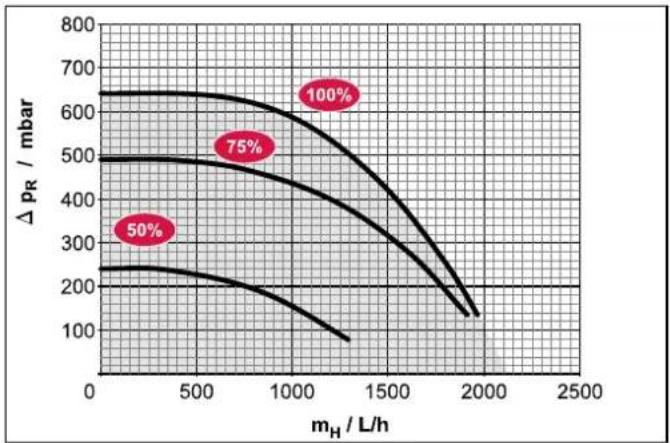
line
| m_H / L/h | Δ p_R / mbar (50%) | Δ p_R / mbar (75%) | Δ p_R / mbar (100%) | | --------- | ------------------ | ------------------ | ------------------- | | 0 | 250 | 500 | 650 | | 500 | 230 | 480 | 630 | | 1000 | 200 | 450 | 600 | | 1500 | 150 | 400 | 550 | | 2000 | 100 | 350 | 500 |P_R Residual pumping height of internal heat circulation pump m_H Flow rate of heating system
Fig. 10-6 Residual pumping height of the internal heat circulation pump
Daikin Altherma EHS(X/H)...P30B and Daikin Altherma
EHS(X/H)(B)08P50B with heating support heat exchanger
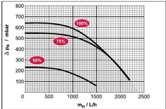
line
| m_H / L/h | Δ p_R / mbar | | --------- | ------------ | | 0 | 250 | | 500 | 230 | | 1000 | 200 | | 1500 | 150 | | 2000 | 100 | | 2500 | 50 |P_R Residual pumping height of internal heat circulation pump m_H Flow rate of heating system
Fig. 10-7 Residual pumping height of internal heat circulation pump Daikin Altherma EHS(X/H)(B)16P50B with heating support heat exchanger
10.3 Tightening torque
| Component Thread | size | Tightening torque |
| Temperature sensor all max. 10 Nm | ||
| Hydraulic line connections (water) | 1" 25 to 30 Nm | |
| Gas line connections (Coolant) | 5/8" 63 to 75 Nm | |
| Liquid line connections (Coolant) | 1/4" 15 to 17 Nm | |
| Liquid line connections (Coolant) | 3/8" 33 to 40 Nm | |
| Backup-Heater 1.5" max. 10 Nm | (hand-tight) | |
Tab. 10-4 Tightening torque
10.4 Circuit diagram Daikin Altherma EHS(X/H)
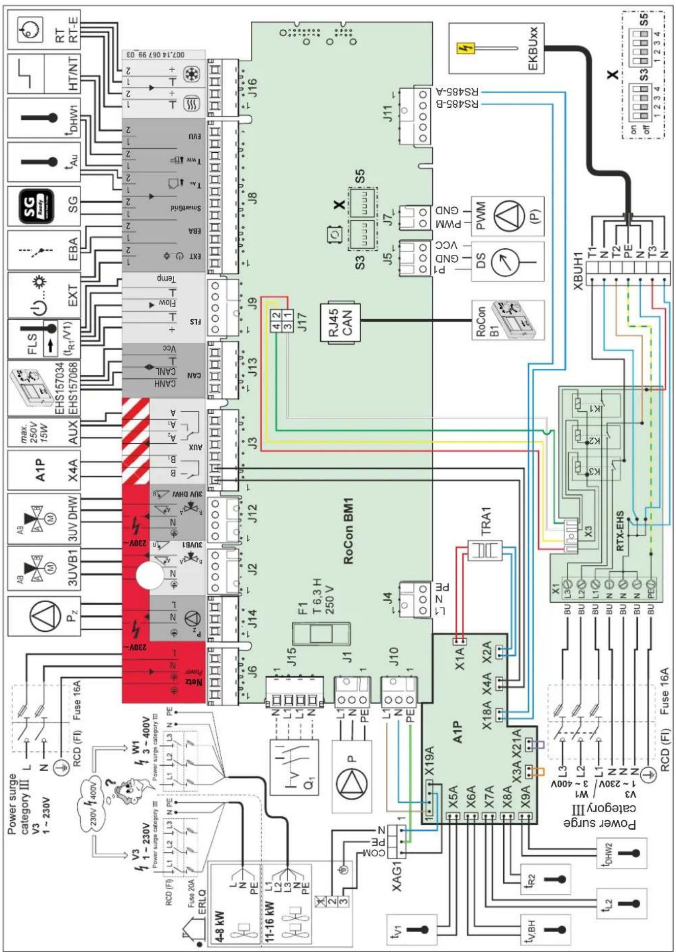
Fig. 10-8 Circuit diagram Daikin Altherma EHS(X/H) - For legend see tab. 4-3
11 Notes
12 List of keywords
Numerics
3-way diverter valve 54
B
Backup heater Electrical connection .... 31
Backup-Heater ....9, 14, 23, 25, 42, 44, 52
C
Characteristic curves for pumps . . . 77
Circuit boards 27
Circuit diagram 78
Circulation pump Minimum flow 43 Vent 42
Convection brake 14
D
Danger of frost 45
Decommissioning 45
Design and components ..... 9
DIP switch 66
Dirt filter 21
Disposal 47
E
EDS (External Demand Signal) ... 30
Electrical connection ..... 25
Backup-Heater 31
Blower-Convector 34
Connection diagrams ..... 26
External unit for heat pump ..... 29
Important information 6
Low tariff connection ..... 35
Mixer module 34
Room station 34
Room thermostat 33
Switching contact (AUX output) .. 35
Symbols, abbreviations ..... 36
Emergency operation 66
Explanation of symbols ..... 4
External heat generator 32
External unit for heat pump ..... 25
Electrical connection 29
Permissible combinations ..... 5
F
Faults and malfunctions Fault codes .... 59 Malfunctions .... 56
Filling connection 45
Filling process Heating system .....40, 53 Outer layer of storage tank .. .40, 52
Filling water 7,23
H
Heating expert log-in 42
Heating support 32
Housing installation room 6
Hydraulic connection Connection examples ..... 67
Connections 9, 16, 17
Important information ..... 7
Installation 21
|
Initial commissioning ..... 41
K
KFE filling connection ..... 45, 53
L
Laying coolant lines 39
Low tariff mains connection (HT/NT) 35
M
Maintenance 49
Malfunctions 55
Minimum flow 43
Mixer module 34
0
Oil trap arc 39
Open controller housing 29
Operating safety 5
P
Pressure test and vacuum ..... 39
R
Re-commissioning 44
Relevant documents .... 3
Reports 55
RESET 56
Room station 34
Room thermostat 33
S
Safety devices 9
Sanitary connection 8
Sensor characteristic lines .....75
Set-up 18
Shutdown
Final 47
Temporary 45
Smart Grid - SG 36
Start-up 41
Control 41
Screed function 43
T
Tapping rate 57
Technical data 70
Basic data 70
Characteristic curves for pumps .. 77
Sensor characteristic lines ..... 75
Technician password 42
Temperature for continuous use . . . 25
Tightening torque 9,77
Top-up water 7,23
U
Use as intended 5
V
Valve drive 54
Venting function 54
W
Water hardness 23
Water shortage protection ..... 23
- 04P30B
- 08P30B
- 08P50B
- 16P50B
4.1.2 Daikin Altherma EHS(X/H)...P50B
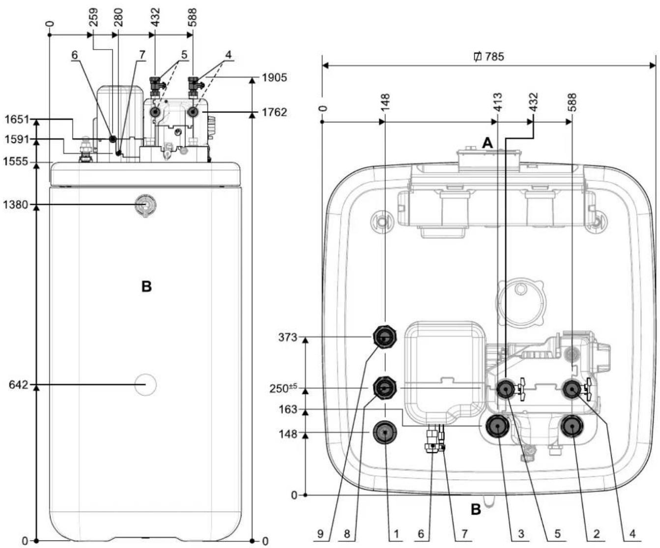
natural_image
Technical line drawing of an electrical enclosure with labeled components (no text or symbols present)Fig. 4-7 Daikin Altherma EHS(X/H) sans capot

ATTENTION!
Fig. 4-14 DB connection kit
natural_image
Isometric technical diagram of a mechanical assembly with no visible text or symbolsnatural_image
Technical line drawing of a mechanical assembly with hoses and components (no text or symbols)natural_image
Technical line drawing of a mechanical assembly with no visible text or symbolsnatural_image
Technical line drawing of a mechanical assembly with pipes and components (no text or symbols)flowchart
graph TD
    A["RoCon BM1"] --> B["SmartGrid"]
    B --> C["T_Ru"]
    B --> D["T_AW"]
    B --> E["EVU"]
    C --> F["1/2"]
    D --> G["1/2"]
    E --> H["1/2"]
    F --> I["SG"]
    G --> I
    H --> I
    I --> J["1/2"]
    style A fill:#f9f,stroke:#333
    style J fill:#bbf,stroke:#333
Fig. 4-43 Raccordement de la Smart Grid
natural_image
Technical line drawing of a mechanical assembly with labeled component A (no text or symbols beyond label)Fig. 5-4 Vannes de purge manuelles
Backup-Heater ..... 10, 15, 24, 26, 43, 45, 53
Raccordement hydraulique Connexions ..... 10, 17, 18
Exemples de branchement ..... 70
Installation 22
Remarques importantes ..... 8
Régulation d'ambiance ..... 35
Daikin Altherma integrated solar unit
Nederlands
Daikin
Altherma
EHS(X/H)(B)
- 04P30B
- 08P30B
- 08P50B
- 16P50B
4.4.3 Montage DB connection kit .....24
4.4.4 Montage Biv connection kit .....24
6.2 Definitieve stillegging 47
ble water installations and general requirements of devices to prevent pollution by backflow)
4.1.2 Daikin Altherma EHS(X/H)...P50B
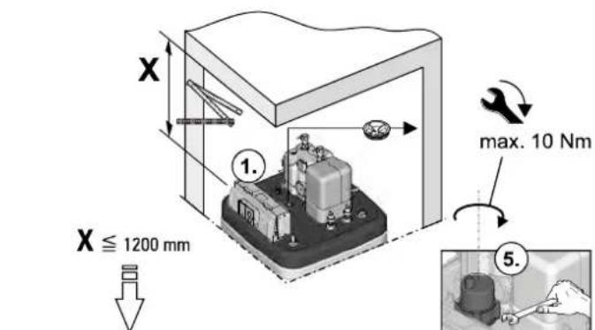
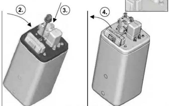
natural_image
Technical line drawing of an electrical enclosure with labeled components (no text or symbols present)Afb. 4-7 Daikin Altherma EHS(X/H) zonder afdekkap

LET OP!
4.4.3 Montage DB connection kit
4.4.4 Montage Biv connection kit
natural_image
Technical line drawing of a mechanical assembly with labeled parts A and B (no text or symbols beyond labels)flowchart
graph TD
    A["A1P"] --> B["X1A"]
    A --> C["X20A"]
    A --> D["X30A"]
    A --> E["X40A"]
    A --> F["X50A"]
    A --> G["X60A"]
    A --> H["X70A"]
    A --> I["X80A"]
    A --> J["X90A"]
    A --> K["X10A"]
    A --> L["X11A"]
    A --> M["X12A"]
    A --> N["X13A"]
    A --> O["X14A"]
    A --> P["X15A"]
    A --> Q["X16A"]
    A --> R["X17A"]
    A --> S["X18A"]
    A --> T["X19A"]
    A --> U["X20A"]
    A --> V["X21A"]
    A --> W["X22A"]
    A --> X["X23A"]
    A --> Y["X24A"]
    A --> Z["X25A"]
    A --> AA["X26A"]
    A --> AB["X27A"]
    A --> AC["X28A"]
    A --> AD["X29A"]
    A --> AE["X30A"]
    A --> AF["X31A"]
    A --> AG["X32A"]
    A --> AH["X33A"]
    A --> AI["X34A"]
    A --> AJ["X35A"]
    A --> AK["X36A"]
    A --> AL["X37A"]
    A --> AM["X38A"]
    A --> AN["X39A"]
    A --> AO["X40A"]
    A --> AP["X41A"]
    A --> AQ["X42A"]
    A --> AR["X43A"]
    A --> AS["X44A"]
    A --> AT["X45A"]
    A --> AU["X46A"]
    A --> AV["X47A"]
    A --> AW["X48A"]
    A --> AX["X49A"]
    A --> AY["X50A"]
    A --> AZ["X51A"]
    A --> BA["X52A"]
    A --> BB["X53A"]
    A --> BC["X54A"]
    A --> BD["X55A"]
    A --> BE["X56A"]
    A --> BF["X57A"]
    A --> BG["X58A"]
    A --> BH["X59A"]
    A --> BI["X60A"]
    A --> BJ["X61A"]
    A --> BK["X62A"]
    A --> BL["X63A"]
    A --> BM["X64A"]
    A --> BN["X65A"]
    A --> BO["X66A"]
    A --> BP["X67A"]
    A --> BQ["X68A"]
    A --> BR["X69A"]
    A --> BS["X70A"]
    A --> BT["X71A"]
    A --> BU["X72A"]
    A --> BV["X73A"]
    A --> BW["X74A"]
    A --> BX["X75A"]
    A --> BY["X76A"]
    A --> BZ["X77A"]
    A --> CA["X78A"]
    A --> CB["X79A"]
    A --> CC["X80A"]
    A --> CD["X81A"]
    A --> DE["RoCon BM1"]
    B --> AF
    BC --> AF
    BD --> AF
    BE --> AF
    BF --> AF
    BG --> AF
    BH --> AF
    BI --> AF
    BJ --> AF
    BK --> AF
    BL --> AF
    BM --> AF
    BN --> AF
    BO --> AF
    CA --> AF
    CB --> AF
    CC --> AF
    AD --> AG["J10 RoCon BM1"]
natural_image
Technical line drawing of a mechanical assembly with no visible text or symbolsnatural_image
Technical line drawing of a mechanical assembly with wires and components (no text or symbols)Afb. 4-25 Bekabeling in de rechter behuizingsdeksel leggen.
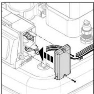
natural_image
Technical diagram of a mechanical assembly with wires and components, no visible text or symbolsnatural_image
Technical line drawing of a mechanical assembly with no visible text or symbolsAfb. 4-28 Bekabeling boilervat bevestigen.
* GWP = Global Warming Potential (broeikaspotentieel)
natural_image
Technical line drawing of a mechanical assembly with pipes and housing (no text or symbols)(accessoires KFE BA)
Afb. 6-3 KFE-vulaansluiting ver- volledigen
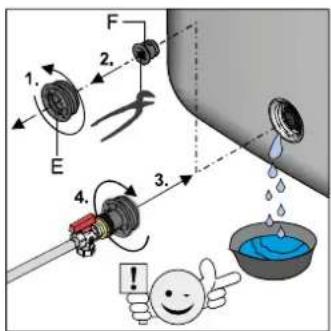
6.2 Definitieve stillegging

WAARSCHUWING!
* GWP = Global Warming Potential (broeikaspotentieel)
Afb. 8-5 Instelling DIP-schakelaar SS2
line
| p / bar | U / V | | ------- | ----- | | 0.5 | 0.0 | | 1.0 | 0.5 | | 1.5 | 1.0 | | 2.0 | 1.5 | | 2.5 | 2.0 | | 3.0 | 2.5 | | 3.5 | 3.0 | | 4.0 | 3.5 |Aanjaagverwarmer .... 9, 14, 23, 25, 42, 44, 52
Minimumdoorstroming 43
N
- 04P30B
- 08P30B
- 08P50B
- 16P50B
4.4.3 Montaggio DB connection kit .....25
4.4.4 Montaggio Biv connection kit .....25
EHS(X/H)...04P30B/08PxxB:
Cu ∅ 6,4 mm (1/4"),
Daikin Altherma EHS(X/H)...16P50B: Cu ∅ 9,5 mm (3/8")
32 Collegamento refrigerante tubatura del gas CuV∅ 15,9 mm (5/8")
3UVB1
Valvola a 3 vie
t_DHW1, t_DHW2
4.1.2 Daikin Altherma EHS(X/H)...P50B
natural_image
Technical line drawing of an electrical enclosure with labeled components (no text or symbols present)4.4.3 Montaggio DB connection kit
A Raccordo mandata (rosso)
B Raccordo ritorno (blu)
Fig. 4-15 Biv connection kit per Daikin Altherma EHS(X/H)B...
natural_image
Isometric technical diagram of a mechanical assembly with no visible text or symbolsnatural_image
Technical line drawing of a mechanical assembly with hoses and components (no text or symbols)natural_image
Technical line drawing of an electrical circuit with wires and components (no text or symbols)natural_image
Technical line drawing of a mechanical assembly with no visible text or symbolsFig. 4-28 Fissare i cavi al serba- toio ad accumulo.
natural_image
Technical line drawing of a mechanical assembly with labeled component A (no text or symbols beyond label)
line
| p / bar | U / V | | ------- | ----- | | 0.5 | 0.0 | | 1.0 | 0.5 | | 1.5 | 1.0 | | 2.0 | 1.5 | | 2.5 | 2.0 | | 3.0 | 2.5 | | 3.5 | 3.0 | | 4.0 | 3.5 |- 04P30B
- 08P30B
- 08P50B
- 16P50B
tion of potable water installations and general requirements of devices to prevent pollution by backflow)
4.1.2 Daikin Altherma EHS(X/H)...P50B

natural_image
Technical line drawing of an electrical enclosure with labeled components (no text or symbols present)Fig. 4-7 Daikin Altherma EHS(X/H) sin cubierta

¡PRECAUCIÓN!
Fig. 4-14 DB connection kit
natural_image
Isometric technical diagram of a mechanical assembly with no visible text or symbolsFig. 4-22 Desbloquear la moldura frontal.

natural_image
Technical line drawing of a mechanical assembly with hoses and components (no text or symbols)natural_image
Technical line drawing of a mechanical assembly with no visible text or symbolsnatural_image
Technical line drawing of a mechanical assembly with no visible text or symbolsnatural_image
Technical line drawing of a mechanical assembly with labeled component A (no text or symbols beyond label)Fig. 5-4 Válvulas de purga manuales
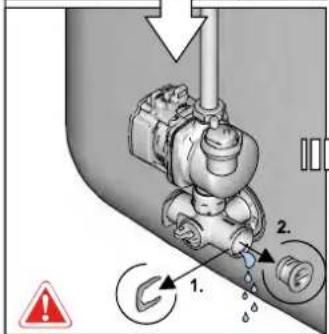
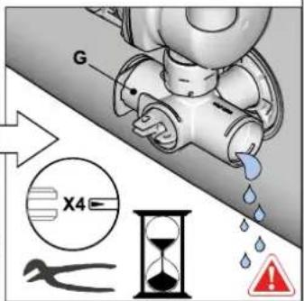
line
| p / bar | U / V | | ------- | ----- | | 0.5 | 0.0 | | 1.0 | 1.0 | | 1.5 | 2.0 | | 2.0 | 3.0 | | 2.5 | 4.0 | | 3.0 | 5.0 | | 3.5 | 6.0 | | 4.0 | 7.0 |Daikin Altherma integrated solar unit
Português
Daikin
Altherma
EHS(X/H)(B)
- 04P30B
- 08P30B
- 08P50B
- 16P50B
t_DHW1, t_DHW2
4.1.2 Daikin Altherma EHS(X/H)...P50B
Fig. 4-6 Retirar a cobertura protectora
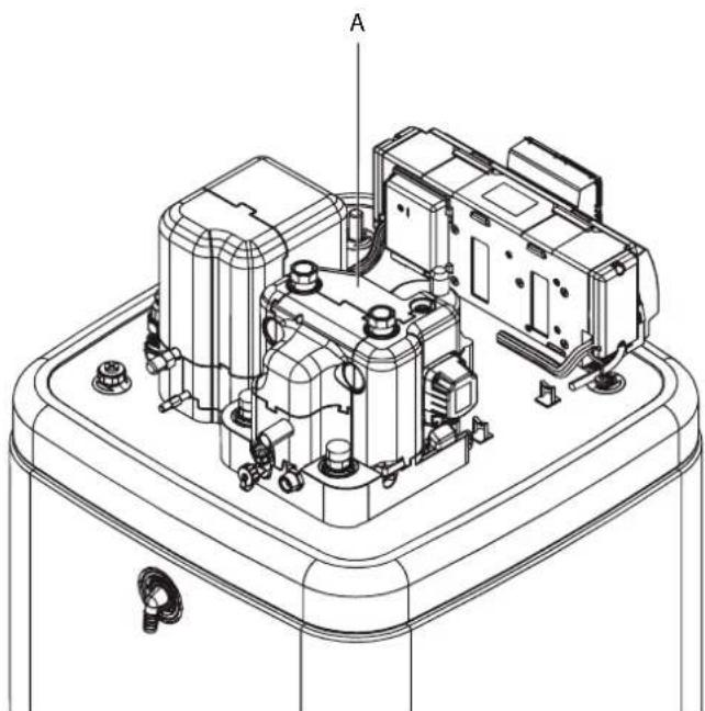
natural_image
Technical line drawing of an electrical enclosure with labeled components (no text or symbols present)Fig. 4-7 Daikin Altherma EHS(X/H) sem tampa de cobertura

CUIDADO!
Fig. 4-8 Retirar o isolamento térmico superior
Fig. 4-14 DB connection kit
natural_image
Technical line drawing of a mechanical assembly with no visible text or symbolsnatural_image
Technical diagram of a mechanical assembly with directional arrows indicating motion or force (no text or symbols present)natural_image
Technical line drawing of a mechanical assembly with wires and components (no text or symbols)natural_image
Technical line drawing of a mechanical assembly with wires and components (no text or symbols)natural_image
Technical line drawing of a mechanical assembly with no visible text or symbolsflowchart
graph TD
    A["RoCon BM1"] --> B["SmartGrid"]
    B --> C["T_Ru"]
    B --> D["T_AW"]
    B --> E["EVU"]
    C --> F["1/2"]
    D --> G["1/2"]
    E --> H["1/2"]
    F --> I["SG"]
    G --> I
    H --> I
    I --> J["1/2"]
    style A fill:#f9f,stroke:#333
    style J fill:#bbf,stroke:#333
natural_image
Technical line drawing of a mechanical assembly with labeled component A (no text or symbols beyond label)Fig. 5-3 Tampa do purgador de ar automático
Fig. 5-4 Válvulas de purga manuais
line
| p / bar | U / V | | ------- | ----- | | 0.5 | 0.0 | | 1.0 | 0.5 | | 1.5 | 1.0 | | 2.0 | 1.5 | | 2.5 | 2.0 | | 3.0 | 2.5 | | 3.5 | 3.0 | | 4.0 | 3.5 |4.4.3 Installation DB connection kit .....24
4.4.4 Installation DB connection kit .....24
4.5 Elektrisk anslutning 24
4.5.1 Komplett kopplingsschema Daikin Altherma EHS(X/H) .....26
t_DHW1, t_DHW2
Lagringstemperaturgivare
t_R2 Returtemperaturgivare
t_V1 Tilloppstemperaturgivare
t_V,BH
Tilloppstemperaturgivare Backup-
Heater

RoCon B1
Manöverdel Daikin Altherma EHS(X/H) reglering
EKSRPS4A
4.1.2 Daikin Altherma EHS(X/H)...P50B
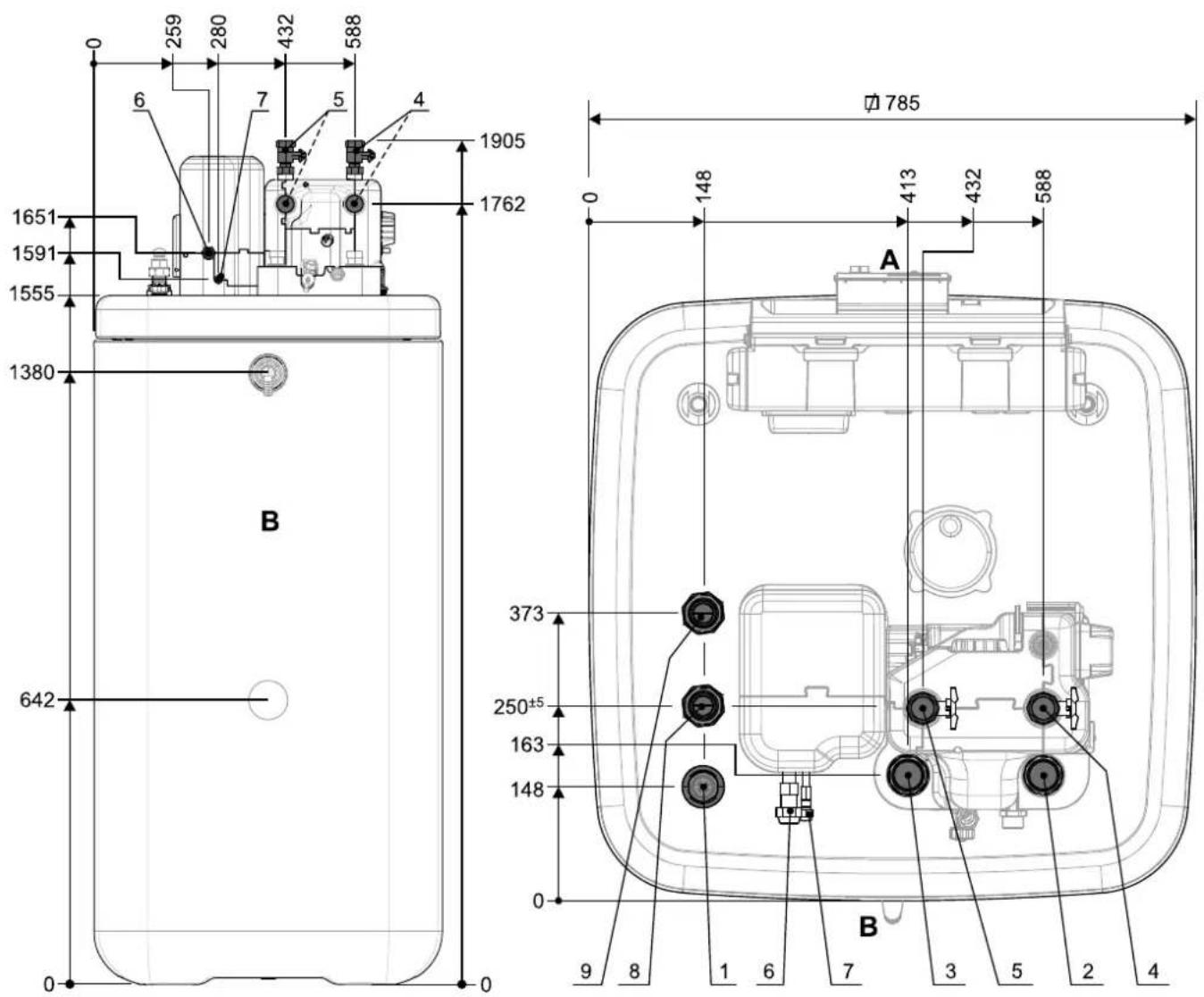
natural_image
Technical line drawing of an electrical enclosure with internal components and mounting base (no text or symbols)4.4.3 Installation DB connection kit
4.4.4 Installation DB connection kit
natural_image
Technical line drawing of a mechanical assembly with labeled parts A and B (no text or symbols beyond labels)flowchart
graph TD
    A["A1P"] --> B["X1A"]
    A --> C["X20A"]
    A --> D["X30A"]
    A --> E["X40A"]
    A --> F["X50A"]
    A --> G["X60A"]
    A --> H["X70A"]
    A --> I["X80A"]
    A --> J["X90A"]
    A --> K["X10A"]
    A --> L["X11A"]
    A --> M["X12A"]
    A --> N["X13A"]
    A --> O["X14A"]
    A --> P["X15A"]
    A --> Q["X16A"]
    A --> R["X17A"]
    A --> S["X18A"]
    A --> T["X19A"]
    A --> U["X20A"]
    A --> V["X21A"]
    A --> W["X22A"]
    A --> X["X23A"]
    A --> Y["X24A"]
    A --> Z["X25A"]
    A --> AA["X26A"]
    A --> AB["X27A"]
    A --> AC["X28A"]
    A --> AD["X29A"]
    A --> AE["X30A"]
    A --> AF["X31A"]
    A --> AG["X32A"]
    A --> AH["X33A"]
    A --> AI["X34A"]
    A --> AJ["X35A"]
    A --> AK["X36A"]
    A --> AL["X37A"]
    A --> AM["X38A"]
    A --> AN["X39A"]
    A --> AO["X40A"]
    A --> AP["X41A"]
    A --> AQ["X42A"]
    A --> AR["X43A"]
    A --> AS["X44A"]
    A --> AT["X45A"]
    A --> AU["X46A"]
    A --> AV["X47A"]
    A --> AW["X48A"]
    A --> AX["X49A"]
    A --> AY["X50A"]
    A --> AZ["X51A"]
    A --> BA["X52A"]
    A --> BB["X53A"]
    A --> BC["X54A"]
    A --> BD["X55A"]
    A --> BE["X56A"]
    A --> BF["X57A"]
    A --> BG["X58A"]
    A --> BH["X59A"]
    A --> BI["X60A"]
    A --> BJ["X61A"]
    A --> BK["X62A"]
    A --> BL["X63A"]
    A --> BM["X64A"]
    A --> BN["X65A"]
    A --> BO["X66A"]
    A --> BP["X67A"]
    A --> BQ["X68A"]
    A --> BR["X69A"]
    A --> BS["X70A"]
    A --> BT["X71A"]
    A --> BU["X72A"]
    A --> BV["X73A"]
    A --> BW["X74A"]
    A --> BX["X75A"]
    A --> BY["X76A"]
    A --> BZ["X77A"]
    A --> CA["X78A"]
    A --> CB["X79A"]
    A --> CC["X80A"]
    A --> CD["X81A"]
    A --> CE["X82A"]
    A --> CF["X83A"]
    A --> CG["X84A"]
    A --> CH["X85A"]
    A --> CI["X86A"]
    A --> CJ["X87A"]
    A --> CK["X88A"]
    A --> CL["X89A"]
    A --> CM["X90A"]
    A --> CN["X91A"]
    A --> CO["X92A"]
    A --> CP["X93A"]
    A --> CQ["X94A"]
    A --> CR["X95A"]
    A --> CS["X96A"]
    A --> CT["X97A"]
    A --> CU["X98A"]
    A --> CV["X99A"]
    A --> CW["X100A"]
flowchart
Electrical wiring diagram for RoCon BM1 system, showing connections between components like relays, switches, and power lines.Bild 4-20 Kretskort RoCon BM1 (basmodul reglering)
Nätspänning 230 V, 50 Hz (Kopplingsschema i denna anvisning)
4.5.6 Nätanslutning Daikin Altherma EHS(X/H)
natural_image
Technical line drawing of a mechanical assembly with no visible text or symbols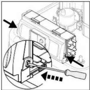
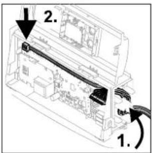
natural_image
Technical line drawing of a mechanical assembly with wires and components (no text or symbols)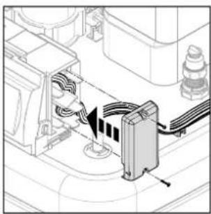
natural_image
Technical line drawing of a mechanical assembly with wires and components (no text or symbols)natural_image
Technical line drawing of a mechanical assembly with pipes and components (no text or symbols)natural_image
Technical line drawing of a mechanical assembly with pipes and housing (no text or symbols)Bild 5-4 Manuella luftventiler
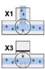

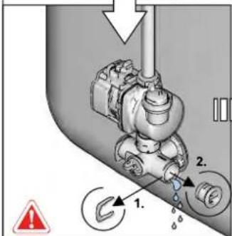
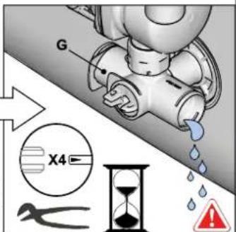
1 Felmeddelande som kod (se tab. 8-2)
line
| p / bar | U / V | | ------- | ----- | | 0.5 | 0.0 | | 1.0 | 0.5 | | 1.5 | 1.0 | | 2.0 | 1.5 | | 2.5 | 2.0 | | 3.0 | 2.5 | | 3.5 | 3.0 | | 4.0 | 3.5 |Backup-Heater ....9, 14, 23, 25, 42, 44, 50
Elektrisk anslutning 31
Blandningsmodul 34
C
- 04P30B
- 08P30B
- 08P50B
- 16P50B
Daikin Altherma integrated solar unit
Polski
4.4.3 Monta DB connection kit .....24
4.4.4 Monta Biv connection kit .....24
Daikin Altherma EHS(X/H)...04P30B/
08PxxB: Cu ∅ 6,4 mm (1/4"),
Daikin Altherma EHS(X/H)...16P50B:
Cu ∅ 9,5 mm (3/8")
t_DHW1, t_DHW2