
EKHH2E200BAV33 - Boiler DAIKIN - Free user manual and instructions
Find the device manual for free EKHH2E200BAV33 DAIKIN in PDF.

| Brand | Daikin |
| Model | EKHH2E200BAV33 |
| Product type | Monobloc air/water heat pump for domestic hot water production |
| Tank capacity | 196 litres |
| Dimensions (H × W × D) | 1744 × 600 × 650 mm |
| Empty weight | 105 kg |
| Power supply | 230 V / 1/N/50 Hz - 16 A (fuse 16A T / circuit breaker 16A curve C) |
| Useful thermal output (heat pump) | 1.82 kW |
| Maximum electrical power | 2.03 kW (pump + heating element) |
| Heating element power | 1.5 kW |
| Refrigerant | R134a, charge 1300 g |
| Maximum water temperature (ECO mode) | 56 °C |
| Maximum water temperature (Auto mode) | 70 °C |
| Operating modes | Economy (ECO), Automatic, Overboost, Anti-legionella, Programmable defrost |
| Protection rating | IPX4 |
| Noise level (indoor) | 53 dB(A) |
| Energy efficiency class | A+ (XL load profile) |
| Routine maintenance | Cleaning the air filter (stainless steel), checking magnesium anodes every 2 years |
| Safety | Manual reset safety thermostat, safety pressostat, compressor and fan protection |
| Spare parts and repairability | Heating element, magnesium anodes, centrifugal fan, air filter, electronic boards — Daikin original parts |
| Solar thermal integration | Yes, model designed with heat exchanger coil (1 m²) |
Frequently Asked Questions - EKHH2E200BAV33 DAIKIN
User questions about EKHH2E200BAV33 DAIKIN
0 question about this device. Answer the ones you know or ask your own.
Ask a new question about this device
Download the instructions for your Boiler in PDF format for free! Find your manual EKHH2E200BAV33 - DAIKIN and take your electronic device back in hand. On this page are published all the documents necessary for the use of your device. EKHH2E200BAV33 by DAIKIN.
USER MANUAL EKHH2E200BAV33 DAIKIN
Installation and user manual
Domestic Hot Water Heat Pump Monobloc type
Installation and user manual
Domestic Hot Water Heat Pump - Monobloc type
1 General safety precautions 3
1.1 About the documentation....3
1.1.1 Meaning of warnings and symbols....3
1.2 For the user....3
1.3 For the installer....4
1.3.1 General 4
2.4 Operating principle 8
2.5 Available versions and configurations....9
3 Handling and transport....9
4 Construction characteristics....11
4.1 Technical characteristics....12
5 Important information....14
5.1 Conformity with European regulations....14
5.2 Degrees of protection provided by enclosures.....14
5.3 Limitations of use 14
5.4 Operating limits 14
5.5 Fundamental safety rules....14
5.6 Information on coolant used....14
6 Installation and connections.... 14
6.1 Preparation of the installation site....15
6.1.1 Securing to the floor.... 15
6.2 Ventilation connection 15
6.2.1 Particular installation conditions.... 17
6.3 Device mounting and connection....18
6.4 Water supply connections....18
6.4.1 Condense drain connections 20
6.5 Solar power system integration 20
6.6 Electrical connections....21
6.6.1 Remote links 21
6.7 Wiring diagram 22
7 Commissioning 23
8 Operation and use....23
8.1 The User Interface 23
8.1.1 Interface keys and display 23
8.1.2 Operating logic 24
8.1.3 Basic management 25
8.2 Particular operations....30
8.2.1 List of equipment parameters 31
9 Maintenance and cleaning....35
9.1 Resetting of safety equipment 35
9.2 Quarterly inspections....35
9.3 Annual inspections....35
9.4 Cleaning of the ventilation filter 36
9.5 Magnesium anodes....36
9.6 Emptying the boiler 36
9.7 Inspection of the electrical resistance compartment .... 37
10 Troubleshooting....38
11 Disposal 38
12 Product fiche 39
1 General safety precautions
1.1 About the documentation
- The original documentation is written in English. All other languages are translations.
- The precautions described in this document cover very important topics, follow them carefully.
- The installation of the system, and all activities described in the installation manual must be performed by an authorized installer.
1.1.1 Meaning of warnings and symbols

DANGER
Indicates a situation that results in death or serious injury.

DANGER: RISK OF ELECTROCUTION
Indicates a situation that could result in electrocution.

DANGER: RISK OF BURNING
Indicates a situation that could result in burning because of extreme hot or cold temperatures.

DANGER: RISK OF EXPLOSION
Indicates a situation that could result in explosion.

WARNING
Indicates a situation that could result in death or serious injury.

WARNING: FLAMMABLE MATERIAL

CAUTION
Indicates a situation that could result in minor or moderate injury.

NOTICE
Indicates a situation that could result in equipment or property damage.

INFORMATION
Indicates useful tips or additional information.
Symbol
Explanation

Before installation, read the installation and operation manual, and the wiring instruction sheet.

Before performing maintenance and service tasks, read the service manual.

For more information, see the installer and user reference guide.
1.2 For the user
- If you are not sure how to operate the unit, contact your installer.
- This appliance can be used by children aged from 8 years and above and persons with reduced physical, sensory or mental capabilities or lack of experience and knowledge if they have been given supervision or instruction concerning use of the appliance in a safe way and understand the hazards involved. Children shall not play with the appliance. Cleaning and user maintenance shall not be made by children without supervision.

WARNING
To prevent electric shocks or fire:
- Do NOT rinse the unit.
- Do NOT operate the unit with wet hands.
- Do NOT place any objects containing water on the unit..

NOTICE
- Do NOT place any objects or equipment on top of the unit.
Do NOT sit, climb or stand on the unit.
- Units are marked with the following symbol:

This means that electrical and electronic products may not be mixed with unsorted household waste. Do NOT try to dismantle the system yourself: the dismantling of the system, treatment of the refrigerant, of oil and of other parts must be done by an authorized installer and must comply with applicable legislation.
Units must be treated at a specialized treatment facility for reuse, recycling and recovery. By ensuring this product is disposed of correctly, you will help to prevent potential negative consequences for the environment and human health. For more information, contact your installer or local authority.
1.3 For the installer
1.3.1 General
If you are not sure how to install or operate the unit, contact your dealer.

NOTICE
Improper installation or attachment of equipment or accessories could result in electric shock, short-circuit, leaks, fire or other damage to the equipment. Only use accessories, optional equipment and spare parts made or approved by Daikin.

WARNING
Make sure installation, testing and applied materials comply with applicable legislation (on top of the instructions described in the Daikin documentation).

CAUTION
Wear adequate personal protective equipment (protective gloves, safety glasses,...) when installing, maintaining or servicing the system.

DANGER: RISK OF BURNING
- Do NOT touch the refrigerant piping, water piping or internal parts during and immediately after operation. It could be too hot or too cold. Give it time to return to normal temperature. If you must touch it, wear protective gloves. - Do NOT touch any accidental leaking refrigerant.

WARNING
Provide adequate measures to prevent that the unit can be used as a shelter by small animals. Small animals that make contact with electrical parts can cause malfunctions, smoke or fire.

CAUTION
Do NOT touch the air inlet or aluminium fins of the unit.

NOTICE
- Do NOT place any objects or equipment on top of the unit. - Do NOT sit, climb or stand on the unit.

NOTICE
Works executed on the outdoor unit are best done under dry weather conditions to avoid water ingress.
In accordance with the applicable legislation, it might be necessary to provide a logbook with the product containing at least: information on maintenance, repair work, results of tests, stand-by periods,...
Also, at least, following information must be provided at an accessible place at the product:
- Instructions for shutting down the system in case of an emergency
- Name and address of fire department, police and hospital
- Name, address and day and night telephone numbers for obtaining service
In Europe, EN378 provides the necessary guidance for this logbook.
- Provide sufficient space around the unit for servicing and air circulation.
- Make sure the installation site withstands the unit's weight and vibration.
- Make sure the area is well ventilated. Do NOT block any ventilation openings.
• Make sure the unit is level.
Do NOT install the unit in the following places:
• In potentially explosive atmospheres. - In places where there is machinery that emits electromagnetic waves. Electromagnetic waves may disturb the control system, and cause malfunction of the equipment.
- In places where there is a risk of fire due to the leakage of flammable gases (example: thinner or gasoline), carbon fibre, ignitable dust.
- In places where corrosive gas (example: sulphurous acid gas) is produced. Corrosion of copper pipes or soldered parts may cause the refrigerant to leak.
1.3.3 Refrigerant
If applicable. See the installation manual of your application for more information.

WARNING
During tests, NEVER pressurize the product with a pressure higher than the maximum allowable pressure (as indicated on the nameplate of the unit).

WARNING
Take sufficient precautions in case of refrigerant leakage. If refrigerant gas leaks, ventilate the area immediately. Possible risks:
- Excessive refrigerant concentrations in a closed room can lead to oxygen deficiency.
| Toxic gas may be produced if refrigerant gas comes into contact with fire. | |
| DANGER: RISK OF EXPLOSIONPump down - Refrigerant leakage. If you want to pump down the system, and there is a leakage in the refrigerant circuit:Do NOT use the unit's automatic pump down function, with which you can collect all refrigerant from the system into the outdoor unit.Possible consequence: Self-combustion and explosion of the compressor because of air going into the operating compressor.Use a separate recovery system so that the unit's compressor does NOT have to operate. | |
| WARNINGAlways recover the refrigerant. Do NOT release them directly into the environment. Use a vacuum pump to evacuate the installation. |
| NOTICE |
| • To avoid compressor breakdown, do NOT charge more than the specified amount of refrigerant. |
| • When the refrigerant system is to be opened, refrigerant must be treated according to the applicable legislation. |
| WARNINGMake sure there is no oxygen in the system. Refrigerant may only be charged after performing the leak test and the vacuum drying. |
- In case re-charge is required, refer to the nameplate of the unit. It states the type of refrigerant and necessary amount.
- The unit is factory charged with refrigerant and depending on pipe sizes and pipe lengths some systems require additional charging of refrigerant.
- Only use tools exclusively for the refrigerant type used in the system, this to ensure pressure resistance and prevent foreign materials from entering into the system.
- Charge the liquid refrigerant as follows:
| If | Then |
| A siphon tube is present (i.e., the cylinder is marked with "Liquid filling siphon attached") | Charge with the cylinder upright.  |
| A siphon tube is NOT present | Charge with the cylinder upside down. |
- Open refrigerant cylinders slowly.
- Charge the refrigerant in liquid form. Adding it in gas form may prevent normal operation.

CAUTION
When the refrigerant charging procedure is done or when pausing, close the valve of the refrigerant tank immediately. If the valve is not closed immediately, remaining pressure might charge additional refrigerant. Possible consequence: Incorrect refrigerant amount.
1.3.4 Water
If applicable. See the installation manual of your application for more information.

NOTICE
Make sure water quality complies with EU directive 98/83 EC.
1.3.5 Electrical

DANGER: RISK OF ELECTROCUTION
- Turn OFF all power supply before removing the switch box cover, connecting electrical wiring or touching electrical parts.
- Disconnect the power supply for more than 1 minute, and measure the voltage at the terminals of main circuit capacitors or electrical components before servicing. The voltage MUST be less than 50 V DC before you can touch electrical components. For the location of the terminals, see the wiring diagram.
- Do NOT touch electrical components with wet hands.
- Do NOT leave the unit unattended when the service cover is removed.

WARNING
If NOT factory installed, a main switch or other means for disconnection, having a contact separation in all poles providing full disconnection under overvoltage category III condition, shall be installed in the fixed wiring.

WARNING
• ONLY use copper wires.
• Make sure the field wiring complies with the applicable legislation.
- All field wiring must be performed in accordance with the wiring diagram supplied with the product.
- NEVER squeeze bundled cables and make sure they do not come in contact with the piping and sharp edges. Make sure no external pressure is applied to the terminal connections.
- Make sure to install earth wiring. Do NOT earth the unit to a utility pipe, surge absorber, or telephone earth. Incomplete earth may cause electrical shock.
• Make sure to use a dedicated power circuit. NEVER use a power supply shared by another appliance.
- Make sure to install the required fuses or circuit breakers;
- Make sure to install an earth leakage protector. Failure to do so may cause electric shock or fire.
- When installing the earth leakage protector, make sure it is compatible with the inverter (resistant to high frequency electric noise) to avoid unnecessary opening of the earth leakage protector.

NOTICE
Precautions when laying power wiring:
- Do not connect wiring of different thicknesses to the power terminal block (slack in the power wiring may cause abnormal heat).
- When connecting wiring which is the same thickness, do as shown in the figure below.


- For wiring, use the designated power wire and connect firmly, then secure to prevent outside pressure being exerted on the terminal board.
- Use an appropriate screwdriver for tightening the terminal screws. A screwdriver with a small head will damage the head and make proper tightening impossible.
• Over-lightening the terminal screws may break them.
Install power cables at least 1 metre away from televisions or radios to prevent interference. Depending on the radio waves, a distance of 1 metre may not be sufficient.

WARNING
- After finishing the electrical work, confirm that each electrical component and terminal inside the electrical components box is connected securely.
- Make sure all covers are closed before starting up the unit.
1.4 Glossary
Dealer
Sales distributor for the product.
Authorized installer
Technical skilled person who is qualified to install the product.
User
Person who is owner of the product and/or operates the product.
Applicable legislation
All international, European, national and local directives, laws, regulations and/or codes that are relevant and applicable for a certain product or domain.
Service company
Qualified company which can perform or coordinate the required service to the product.
Installation manual
Instruction manual specified for a certain product or application, explaining how to install, configure and maintain it.
Operation manual
Instruction manual specified for a certain product or application, explaining how to operate it.
Accessories
Labels, manuals, information sheets and equipment that are delivered with the product and that need to be installed according to the instructions in the accompanying documentation.
Optional equipment
Equipment made or approved by Daikin that can be combined with the product according to the instructions in the accompanying documentation.
Field supply
Equipment not made by Daikin that can be combined with the product according to the instructions in the accompanying documentation.
2 Introduction
This installation and maintenance manual is to be considered an integral part of the present heat pump (hereafter referred to as equipment).
The manual must be kept for future reference until the heat pump itself has been dismantled. This manual is intended for both the specialised installer (installers – maintenance technicians) as well as the end user.
The installation modes to be complied with in order to achieve a correct and safe operation of the equipment as well as methods of use and maintenance are described in this manual.
In case of the sale of the equipment or the change of owner, the manual must accompany the equipment to its new destination.
Before installing and/or using the equipment, read this instruction manual carefully and, in particular, chapter 5 relating to safety.
The manual must be kept together with the equipment and, in any case, it must always be at the disposal of the qualified personnel in charge of installation and maintenance.
The following symbols are used inside the manual in order to rapidly find the most important information:

Information on safety

Procedures to follow

Information/ Suggestions
2.1 Products
Dear Customer,
Thank you for having purchased this product.
Our company has always paid a great deal of attention to environmental problems, therefore, it has used technologies and materials with a low environmental impact to manufacture its products in conformity with RAEE 2012/19/UE and RoHS 2011/65/UE community standards.
2.2 Disclaimer
The conformity of the content of these user instructions with hardware and software has been submitted to thorough verification. Regardless of this, it is still possible for some non-compliances to occur; therefore, no liability will be assumed for complete conformity. In the interest of achieving technical perfection, we reserve the right to carry out modifications to the equipment construction or to data at any time whatsoever. Therefore we do not accept any liability
claims whatsoever attributable to instructions, figures, drawings or descriptions, without prejudice to errors of any kind.
The Supplier shall not be held responsible for damages attributable to misuse, improper use, or as a consequence of unauthorised repairs or modifications.

WARNING!
The equipment can be used by children of at least 8 years of age as well as by people with reduced physical, sensory or mental abilities or by those who lack the necessary experience or knowledge, as long as they are supervised or after they have received instructions relating to the safe use of the equipment as well as explanations relating to the use of such equipment.
Children must not play with the equipment. Cleaning and maintenance intended to be carried out by the user must not be performed by unsupervised children.
2.3 Copyright
These user instructions contain information protected by copyright. It is forbidden to photocopy, duplicate, translate or record these user instructions on memory equipment, either in whole or in part without prior authorisation of Daikin. Any breaches shall be subject to the payment of compensation for any damage caused. All rights are reserved, including those deriving from the issuing of patents or the registration of utility models.
2.4 Operating principle
The equipment belonging to the 1.9 kW and 2.9 kW series is capable of producing domestic hot water mainly by using heat pump technology. A heat pump is capable of transferring thermal energy from a low temperature source to another with a higher temperature and vice versa (heat exchangers).
The equipment uses a water circuit consisting of a compressor, an evaporator, a condenser and a lamination valve; a liquid/gas coolant flows inside this circuit (see paragraph 4.6).
The compressor creates a difference in pressure inside the circuit that allows a thermodynamic cycle to be obtained: this sucks the coolant fluid in through an evaporator, where the fluid itself evaporates at a low pressure by absorbing heat, it is compressed and driven towards the condenser where the fluid condenses at a high pressure releasing the absorbed heat. After the condenser, the fluid passes through the so-called "lamination valve" and by losing pressure and the temperature starts to vaporise, it re-enters the evaporator and the cycle starts all over again.
flowchart
graph TD
    A["Evaporator"] --> B["Condenser"]
    B --> C["Tank"]
    C --> D["Hot water"]
    D --> E["Cold water"]
    F["Air"] --> G["Lamination valve"]
    G --> H["Compressor"]
    H --> I["Condenser"]
    style A fill:#f9f,stroke:#333
    style B fill:#ccf,stroke:#333
    style C fill:#cfc,stroke:#333
    style D fill:#fcc,stroke:#333
    style E fill:#cff,stroke:#333
    style F fill:#ffc,stroke:#333
    style G fill:#cfc,stroke:#333
    style H fill:#fcc,stroke:#333
    style I fill:#ffc,stroke:#333
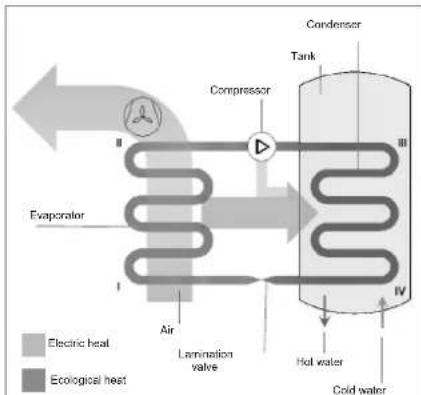
Fig. 1 – Operating principle
The operating principle of the equipment is as follows (Fig. 1):
I-II: The coolant fluid sucked in by the compressor flows inside the evaporator and while it evaporates, it absorbs the "ecological" heat given by the air.
At the same time, the ambient air is sucked in by the equipment by a fan; the air loses it heat by passing over the finned-tube battery of the evaporator;
II-III: The coolant gas passes inside the compressor and it under goes an increase in pressure that causes a rise in temperature; transforming this into superheated steam;
III-IV: Inside the condenser, the coolant gas releases its heat to the water inside the tank (boiler). This exchange process makes it possible for the coolant to pass from superheated steam to a liquid state by condensing at a constant pressure and undergoing a reduction in temperature;
IV-I: The liquid coolant passes through the lamination valve, it undergoes a sudden drop in both pressure and temperature and it partially vaporises bringing pressure and temperature back to the initial conditions. The thermodynamic cycle can begin.
2.5 Available versions and configurations
The heat pump is available, in relation to the thermal power (1.9 kW version), which can be set up in different configurations, depending on the possible integrations with other heating sources (e.g. solar thermal, biomass power, etc.).
| Version | Configuration description |
| EKHH2E200AAV3 | Air source heat pump for the production of domestic hot water |
| EKHH2E200BAV33 | |
| EKHH2E260AAV3 | |
| EKHH2E260PAAV3 | Air source heat pump for the production of domestic hot water suitable for use with the solar power system. |
3 Handling and transport
The equipment is supplied in a cardboard box (*). It is fastened to a pallet with three screws.
Use a fork-lift truck or a pallet truck in order to unload the equipment: it is opportune for these to have a load capacity of at least 250 kg.
In order to make it easier to loosen the fixing screws the packaged equipment may be put in a horizontal position on its back side.
The unpacking operations must be carried out carefully so as not to damage the equipment enclosure if this is carried out with knives or cutters to open the cardboard packaging.
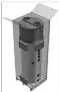
natural_image
3D rendering of a cylindrical mechanical component with mounting holes and housing (no text or symbols visible)After having removed the packaging, make sure that the unit is intact. If in doubt, do not use the equipment and seek help from authorised technical staff.
In conformity with environmental protection regulations, make sure that all the accessories supplied have been removed before discarding the packaging.
WARNING!
Packaging items (staples, cardboard boxed, etc.) must not be left within the reach of children as they are dangerous.
(*) Note: at Daikin's discretion, the type of packaging may be subject to change.
For the entire period in which the equipment remains idle, waiting to be used, it is opportune to protect it from atmospheric agents.
Positions permitted for transporting and handling:
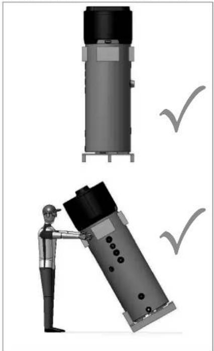
natural_image
Illustration of a worker assembling a cylindrical device with checkmarks indicating inspection (no text or symbols present)
WARNING!
During the product handling and installation stages, it is forbidden to put the upper part of the device under any kind of stress whatsoever due to the fact that it is not of a structural nature.

WARNING!
The equipment can be transported horizontally only during the last km according to what indicated above (see "Positions permitted for transporting and handling") and taking care of positioning some supports on the lower side of the boiler in order not to lean against the upper part, which is not of a structural nature. When the equipment is transported horizontally, the display must be oriented toward the upper side.
Positions that are not permitted for transporting and handling purposes:
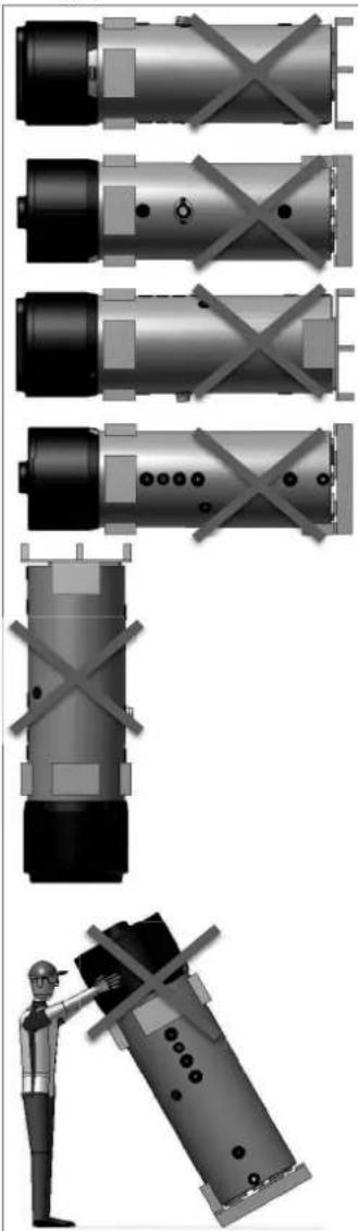
natural_image
Technical illustration of industrial cylindrical components with cross-bracing, plus a worker inspecting a device (no text or symbols)4 Construction characteristics
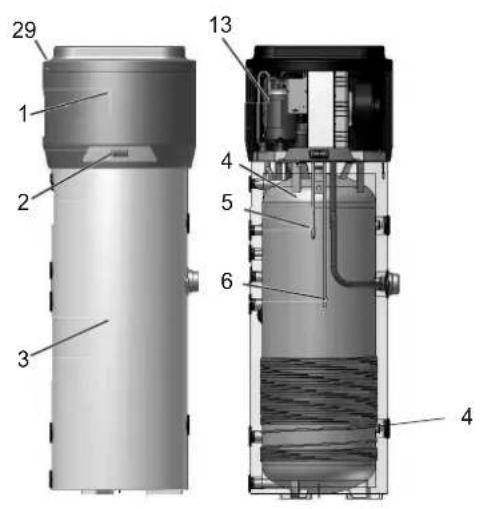
| 1 | Heat pump. |
| 2 | Control panel. |
| 3 | Enclosure in embossed ABS. |
| 4 | Steel tank (boiler) enamelled according to UNI standards (capacity: 200; 260 litres). |
| 5 | Upper boiler probe. |
| 6 | Lower boiler probe. |
| 7 | Coolant recharge. |
| 8 | Ambient air recirculation fan. |
| 9 | Lamination valve. |
| 10 | High-efficiency finned evaporator. The quantity of fluid put into this is regulated by an appropriate thermostatic valve. |
| 11 | Air inlet (∅ 160 mm). |
| 12 | Air outlet (∅ 160 mm). |
| 13 | Hermetically-sealed rotary compressor. |
| 14 | Replaceable magnesium anode. |
| 15 | (1.5 kW - 230 W) Electric heating element |
| 16 | Condenser pump discharge line. |
| 17 | Condenser return. |
| 18 | Replaceable magnesium anode. |
| 19 | Hot water outlet connection joint (G 1"). |
| 20 | Recirculation fitting (G 3/4"). |
| 21 | Inlet, coil fitting for solar thermal power system (G 1"1/4; 1 m2 exchange surface). |
| 22 | Condensate drain (G 1/2"). |
| 23 | Outlet, coil fitting for solar thermal power system (G 1"1/4; 1 m2 surface). |
| 24 | Cold water inlet connection joint (G 1"). |
| 25 | 50 mm polyurethane insulation. |
| 26 | Automatic resetting safety pressure switch. |
| 29 | Air inlet filter. |
| 30 | 1⁄2"G fitting for probe immersion sleeve |

4.1 Technical characteristics
| 1.9 kW | |||||||
| Descriptions | u.m. | EKHH2E200AAV3 | EKHH2E26BAAV3 | EKHH2E260PAAV3 | EKHH2E200BAV33 | ||
| HP thermal power yield kW | 1.82 | ||||||
| Total thermal power | kW | 3.4 | |||||
| Heating time (1) | h:min | 8:17 | 10:14 | 10:14 | 7:05 | ||
| Heating time in BOOST mode (1) | h:min | 3:58 | 5:06 | 5:06 | 3:02 | ||
| Thermal losses (2) | W | 60 | 70 | 71 | 53 | ||
| Electrical data | |||||||
| Power supply | V | 1/N/230 | |||||
| Frequency | Hz | 50 | |||||
| Degree of protection IPX4 | |||||||
| HP maximum absorption kW | 0.53 | ||||||
| Average absorption | kW | 0.43 | |||||
| Heating element + HP maximum absorption | kW | 2.03 | |||||
| Electric heating element power | kW | 1.5 | |||||
| Maximum current in HP | A | 2.4 | |||||
| Required overload protections | A | 16A T fuse/ 16A automatic switch, characteristic C (to be expected during installation on power supply systems) | |||||
| Internal protection | Single safety thermostat with manual reset on a resistive element | ||||||
| Operating conditions | |||||||
| Min.+ max temperature heat pump air intake (90% R.H.) | °C | -7÷38 | |||||
| Min. + max temperature installation site | °C | 5÷38 | |||||
| Working temperature | |||||||
| HP Maximum settable temperature - ECO cycle | °C | 56 | |||||
| Maximum settable temperature in an AUTOMATIC cycle | °C | 70 | |||||
| Compressor | Rotary | ||||||
| Compressor protection | Thermal circuit breaker with automatic reset | ||||||
| thermodynamic circuit protection type | Safety pressure switch with automatic reset | ||||||
| Fan | Centrifugal | ||||||
| Ejection outlet diameter mm | 160 | ||||||
| Revolutions per minute | rpm | 1650÷2100 | |||||
| Nominal air capacity | m^3/h | 350*500 | |||||
| Max. pressure head available | Pa | 120 | |||||
| Motor protection Internal thermal circuit breaker with automatic reset | |||||||
| Condenser Wrapped externally, not in contact with water | |||||||
| Coolant R134a | |||||||
| Load | g | 900 900 900 1300 | |||||
| Water storage | |||||||
| Water storage nominal capacity | I | 196 252 242 196 | |||||
| Max. quantity of hot water that can be used Vmax (3) | I | 275 342 342 266 | |||||
| Coil for connection to solar thermal power system | m^2 | N/A N/A 1.0 m | 2 | N/A | |||
| Cathodic protection | Mg AnodeØ26x400 mm | 1 x Mg anodeØ26x250 mm+1 x Mg anodeØ26x250 mm | Mg anode Ø26x400 mm | ||||
| Insulation | 50 mm high-density polyurethane foam | ||||||
| Defrosting | Active with Hot Gas valve | ||||||
| Dimensions | mm | H1707xD600xDmax650 | H2000xD600xDmax650 | H2000xD600xDmax650 | H1744xD600xDmax650 | ||
| Transport weight | kg | 103 115 132 105 | |||||
| Sound power indoors Lw(A) (4) | dB(A) | 53 | |||||
| Automatic anti-Legionnella disinfection cycle (5) | YES | ||||||
| Maximum working pressure | Bar | 7 | |||||
| (1) temperature of incoming air supply 7°C (6°C), temperature of boiler storage environment 20°C, water heated from 10°C to 55°C, (according to UNI EN 16147-2011 and 2017)(2) measurements carried out according to UNI EN 12897-2006(3) measurements carried out according to UNI EN 16147-2011 and 2017(4) measurements carried out according to EN 12102-2013(5) automatic activation every 30 days of operation | |||||||
5 Important information
5.1 Conformity with European regulations
The present heat pump is a device intended for domestic use in conformity with the following European directives:
- 2011/65/UE Directive on the restrictions of use of certain hazardous substances in electric and electronic equipment (RoHS);
- Directive 2014/30/UE - Electromagnetic compatibility (EMC);
• Directive 2014/35/UE – Low Voltage Directive (LVD)
• Directive 2009/125/CE Ecodesign Requirements.
5.2 Degrees of protection provided by enclosures
The degree of protection of the equipment is equal to: IPX4.
5.3 Limitations of use

WARNING!
This device has not been designed, nor is it intended for use within hazardous environments (due to the presence of potentially explosive atmospheres – according to ATEX standards or with a requested IP level exceeding that of the equipment) or in applications that require (fault-tolerant, fail-safe) safety characteristics such as in circuit-breaking systems and/or technologies or in any other context in which the malfunctioning of an application could cause death or injury to people or animals or serious damage could be caused to objects or the environment.

N.B.
In the event of a product breakdown or fault, this could cause damage (to people, animals and goods). It is necessary to arrange for a separate functional monitoring system with alarm functions in order to avoid such damage being caused. Moreover, it is necessary to arrange for a back-up service in case of failure!
5.4 Operating limits
The above mentioned device is intended to be used exclusively for the heating of domestic hot water within the foreseen limitations of use.
The equipment can only be installed and started up for the intended use within closed heating systems in conformity with the EN 12828 standard.

N.B.
Daikin shall not be held responsible under any circumstances in the event that the equipment is used for other purposes than for which it has been designed and as regards any installation errors or equipment misuse.

WARNING!
It is forbidden to use the device for purposes other than those intended. Any other use is to be considered improper and therefore not allowed.

N.B.
During the design and construction stage of the systems, current local rules and provisions are complied with.
5.5 Fundamental safety rules
• The device must be used by adults;
- Do not open or disassemble the device when this is connected to the power supply;
- Do not touch the device with wet or humid body parts when barefoot;
- Do not pour or spray the device with water;
- Do not stand, sit and/or rest anything on the device.
5.6 Information on coolant used
This device contains fluorinated greenhouse gas included in the Kyoto protocol. Do not discard such gas into the environment.
Coolant type: HFC-R134a.

N.B.
Maintenance and disposal operations must be carried out only by qualified personnel.
6 Installation and connections

WARNING!
Installation, commissioning and maintenance of the device must be performed by qualified and authorised personnel. Do not attempt to install the device yourself.
6.1 Preparation of the installation site
The installation of the device must be carried out in a suitable place in order to allow the normal use and adjustment operations, together with ordinary and extraordinary maintenance to be performed.
Therefore it is important to allow for the necessary working space by referring to the dimensions shown in Fig. 2.
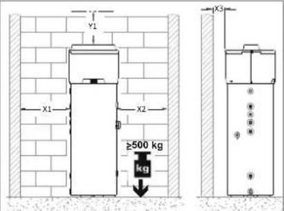
Fig. 2 – Minimum spaces
| Model | X1 | X2 | X3 | Y1 |
| mm | Mm | mm | mm | |
| EKHH2E200AAV3 | 650 | 650 | 200 | 300 |
| EKHH2E200BAV33 | ||||
| EKHH2E260AAV3 | ||||
| EKHH2E260PAAV3 |
Moreover, the premises must:
- Have adequate water and power supply lines;
- Be available and ready for connection to the condense drain;
- Be available and ready with adequate discharge pipes in case of damage caused to the boiler or actuation of the safety valve or breakage of pipes/connections;
- Have containment systems in case of serious water leaks;
- Be sufficiently lit (where appropriate);
• Not measure less than 20 m ^3 ; - Be frost-proof and dry.

WARNING!
In order to avoid the propagation of mechanical vibrations, do not install the equipment on floor slabs with wooden beams (e.g. in lofts).
6.1.1 Securing to the floor
To secure the product to the floor, fasten the supplied brackets as shown in fig. 3.
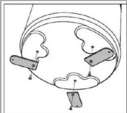
natural_image
Diagram of a mechanical or electrical component with three labeled parts and connecting lines (no text or symbols)Fig.3 - Fastening brackets
Then secure the unit to the floor with the aid of suitable plugs not supplied, as shown in fig. 3a.
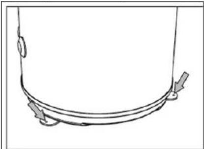
natural_image
Simple line drawing of a curved pipe or tube with directional arrows indicating flow or movement (no text or symbols)Fig.3a - Securing to the floor
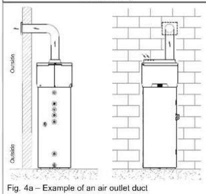
6.2 Ventilation connection
Apart from the space indicated in paragraph 6.1, the heat pump requires adequate ventilation.
It is necessary to create a dedicated air duct as indicated in the following illustration (Fig. 4a and 4b).
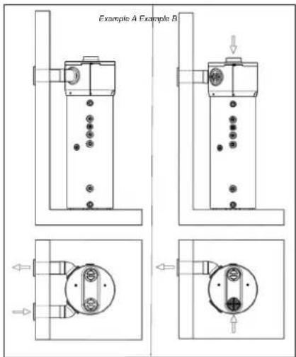
Fig. 4 – Example of dual duct connection on back side (optional)
Moreover, it is important to ensure an adequate ventilation of the premises where the equipment is to be installed.
An alternative solution is indicated in the following illustration (Fig. 4 and 4b): this consists of a second duct that draws air in from outside instead of directly from inside the premises.
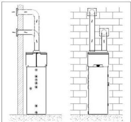
natural_image
Technical line drawing of two utility pole installation methods, one with pipe support and the other with a brick wall (no text or symbols)Fig. 3b – Example of dual duct connection
Carry out the installation of each air duct taking care that:
- The weight of such does not adversely affect the equipment itself;
- Maintenance operations can be carried out;
- This is adequately protected so as to avoid the accidental intrusion of material inside the equipment itself;
- It doesn't exceed the maximum suggested length of 6 meters (with 2 elbow junctions 90^ ).
- The maximum total allowable pressure drop for all components, including through holes for mounting on external wall, within the pipe system does not exceed 120 Pa.

During operation, the heat pump tends to lower the ambient temperature if the external air duct is not carried out.

An appropriate protection grid must be installed in line with the discharge pipe conveying air to the outside with the aim of avoiding foreign bodies from entering the equipment. In order to guarantee maximum device performance, the grid chosen must ensure low pressure loss.

In order to avoid the formation of condensate: insulate the air discharge pipes and the air duct cover connections with steam-tight thermal cladding of an adequate thickness.

If it is considered necessary in order to prevent flow noise, sound mufflers can be mounted.
Fit the pipes, the wall through holes and the connections to the heat pump with vibration damping systems.

WARNING!
The simultaneous operation of an open-flue firebox (e.g. an open-flue fireplace) together with the heat pump causes a dangerous environmental pressure drop. This could cause the backflow of exhaust gas into the environment itself.
Do not operate the heat pump together with an open-flue firebox.
Use only sealed-chamber fireboxes (approved) with a separate duct for combustion air.
Keep the doors to the boiler room closed and hermetically sealed if it does not have a combustion air supply in common with inhabited areas.
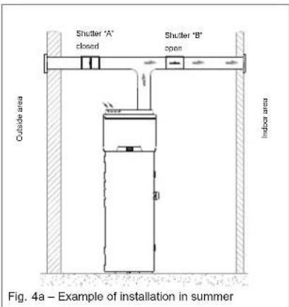
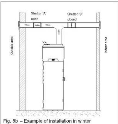
6.2.1 Particular installation conditions
One of the peculiarities of the heat pump heating system is represented by the fact that these units cause a considerable reduction of the air temperature that is generally ejected from inside the home. Apart from being colder than the ambient air, the exhaust air is also completely dehumidified; for this reason, it is possible to allow the air to flow back into the home in order to cool specific environments or rooms during the summer. Installation consists of the splitting of the discharge pipe to which two shutters are applied ("A" and "B") with the aim of directing the air flow either towards the inside (Fig. 5a) or the outside of the home (Fig. 5b).
6.3 Device mounting and connection
The device must be installed on a stable, flat floor surface that is not subject to vibration.
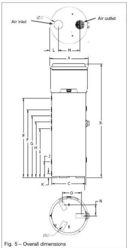
| (260 versions) | A | B | C | ∅∅D | E | F | G |
| mm | mm | mm | mm | mm | mm | mm | |
| 650 | 2000 | 600 | 160 | 1391 | 1190 | 1085 | |
| H | I | J | K | L | M | N | |
| mm | mm | mm | mm | mm | mm | mm | |
| 980 | 860 | 275 | 70 | 150 | 380 | 195 | |
| O | ∅∅P | Q | R | ||||
| mm | mm | mm | mm | ||||
| 337.5 | 10 | 850 |
| (2001 versions) | A | B | C | ∅∅D | E | F | G |
| mm | mm | mm | mm | mm | mm | mm | |
| 650 | 1504 1714 | 600 | 160 | 891 1101 | 670 795 | ||
| H | I | J | K | L | M | N | |
| mm | mm | mm | mm | mm | mm | mm | |
| / | 590 | 275 | 70 | 150 | 380 | 195 | |
| O | ∅∅P | Q | R | ||||
| mm | mm | mm | mm | ||||
| 337,5 | 10 | 535 560 |
6.4 Water supply connections
Connect the cold water inlet and the outlet pipes to the appropriate connection points (Fig.7).
The table below shows the characteristics of the connection points.
| Pos. | Description | Connection/hole |
| 1 | Cold water inlet pipe | G 1" |
| 2 | Hot water outlet pipe | G 1" |
| 3 | Condensate drain | G 1⁄2" |
| 4 | Recirculation pipe | G 3⁄4" |
| 5 | Coil for solar thermal power | G 1" ^1/4 |
| 6 | Probe immersion sleeve (only in models provided with it) | ^1/2 G |
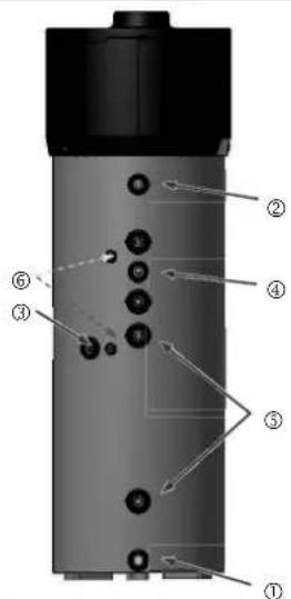
Fig. 7 – Water supply connections
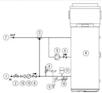
The following illustration (Fig. 8) shows an example of a water supply connection.
flowchart
graph TD
    ① --> IN
    IN --> ②
    ② --> ③
    ③ --> OUT
    ④ --> ⑤
    ⑤ --> ⑥
    ⑥ --> ⑧
    ⑧ --> ⑩
    ⑩ --> ⑪
    ⑪ --> ⑬
    ⑬ --> ⑭
    ⑭ --> ⑩
    ⑩ --> ⑨
    ⑨ --> ⑩
    ⑩ --> ⑥
    ⑥ --> ③
① Water inlet pipe:
② Shut-off valve;
© Automatic thermostat mixing equipment
④ Heat pump
⑤ Ricirculation pump
© Spring check valve
② Hot water outlet pipe
⑧ Safety valve
© Inspectionable end of discharge pipe
② Drain tap
Expansion vessel
⑲ Pressure regulator
39 Pressure gauge
Fig. 8 – Example of the water supply system
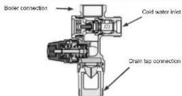
Fig. 8a – Example of heavy series safety valve

N.B.
It is compulsory to install a dirt filter on the cold water inlet pipe. The equipment should not work with water hardness lower than 12°F; on the contrary, when the water hardness is particularly high (higher than 25°F), it is recommended to use a water softener, properly calibrated and monitored; in this case the residual hardness should not fall below 15°F.

PLEASE NOTE!
It is advisable for the system installer to install a 7-bar safety valve on the cold water intake pipe (Fig. 8a).

N.B.
The safety equipment for protection against over pressure must be operated regularly in order to remove limescale deposits and to check that it is not blocked (Fig. 8a)

N.B.
For a proper installation of the equipment, a hydraulic safety group in accordance to UNI EN 1487:2002 standard should be provided. It should include at least: a shut-off valve, a check valve, a control device of the check valve, a safety valve, a device to interrupt the water load (Fig. 8a)

N.B.
The drain hose connected to the equipment for overpressure protection must be installed with a continuous downward slope (slope>3°) and in an area protected against the formation of ice (Fig. 8)

WARNING!
In case an expansion vessel is not being installed, make sure that in the cold water intake there is not any non-return valve installed.

WARNING!
The heat pump for the production of domestic hot water is capable of heating water up to more than 60°C. For this reason, as a protection against burns, it is necessary to install an automatic thermostat mixing equipment to the hot water pipe (Fig. 8).
6.4.1 Condense drain connections
Condensate that forms during the operation of the heat pump flows through an appropriate discharge pipe (G 1/2") that passes inside cladding and it comes out on the side of the equipment.
This must be connected to a duct via a siphon so that the condensate can flow freely (Fig. 9a or Fig. 9b).
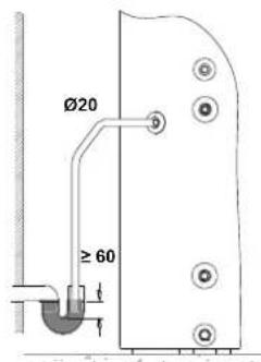
Fig. 9a – Examples of condensate drain connection via siphon
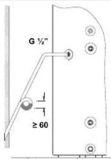
Fig. 9b – Example of condensate drain connection using siphon with water interceptor
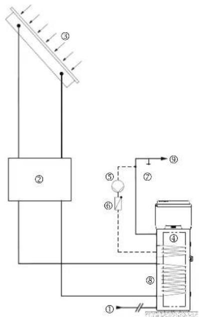
6.5 Solar power system
integration
The following illustration (Fig. 10) shows an example of solar power system integration.
flowchart
graph TD
    A["①"] --> B["②"]
    B --> C["③"]
    C --> D["④"]
    D --> E["⑤"]
    E --> F["⑥"]
    F --> G["⑦"]
    G --> H["⑧"]
    H --> I["⑨"]
    style A fill:#f9f,stroke:#333
    style B fill:#ccf,stroke:#333
    style C fill:#cfc,stroke:#333
    style D fill:#fcc,stroke:#333
    style E fill:#cff,stroke:#333
    style F fill:#ffc,stroke:#333
    style G fill:#cfc,stroke:#333
    style H fill:#fcc,stroke:#333
    style I fill:#ffc,stroke:#333
① Cold water intake pipe
② Solar power system pump and accessories
⑤ Solar collectors
① Heat pump
① Recirculation pump
© Spring check valve
Drain lap
© Solar thermal power coil
© Hot water outlet pipe
Fig. 10 – Example of solar power system integration
6.6 Electrical connections
The appliance is supplied with a power supply cable (should the latter need to be replaced, use only original spare parts supplied by the manufacturer or its service agent). It is powered through a flexible cable and a socket/plug combination (Fig. 11 and Fig. 12). An earthed Schuko socket with separate protection is needed for the connection to the mains power supply.

It is advisable to carry out a check on the electrical system to verify conformity to the regulation in force.
Verify that the electrical system can suitably withstand the water heater's maximum power consumption values (refer to data plate), in terms of the size of the cables and their conformity to the regulation in force. It is forbidden to use multiple outlet sockets, extension cable or adaptor. The earth connection of the appliance is required. It is forbidden to use piping from the water, heating and gas systems for earthing the appliance Prior to operating the machine, make sure that the electricity mains voltage conforms to the value indicated on the appliance's data plate.
The manufacturer of the appliance shall not be held liable for any damage caused by failure to earth the system or due to anomalies in the electric power supply. To disconnect the appliance from the mains, use a bipolar swith complying with all applicable CEI-EN regulations in force (minimum distance between contacts 3 mm, switch preferably equipped with fuse). The appliance must comply with European and national standards, and must be protect by a 30 mA differential switch.
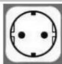
Fig. 11 -A Schuko socket
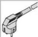
Fig. 12 – Equipment plug
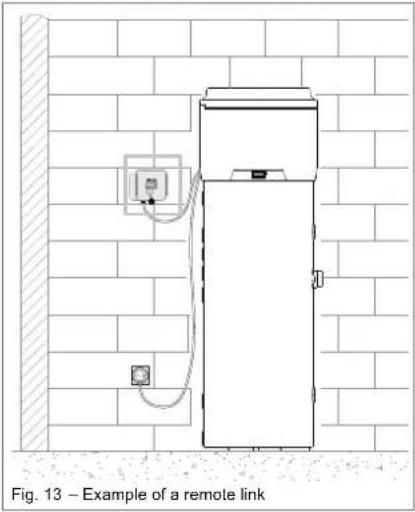
6.6.1 Remote links
The equipment is designed to be connected to other remote energy systems (photovoltaic and solar thermal power systems).
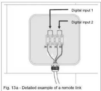
The user interface has two digital inputs with the following functions:
- Digital 1: Input from the solar thermal power system. When a free contact is established between terminals 30 and 31 (cable: brown/yellow) and the water temperature measured by lower probe is higher than SP8, the heat pump stops and water is heated up by the solar panels; the heat pump starts again when the contact is released
and time set by C13 is passed or immediately if the lower probe temperature is lower than SP8.
- Digital 2: Input from photovoltaic system. When a free contact is established between terminals 31 and 32 (cable: green/white) and the heat pump reaches the SP5 temperature (default setting 62°C), the hot water nominal temperature is raised by 7°C. It is possible to change the SP6 parameter (e.g.: raising the temperature from 62°C to 70°C) so that, if there is enough PV electrical energy, the heat drop from 62°C to 70°C is made by the immersion electric heating element (if SP6 is the same as SP5, the electric heating element will never activate).
6.6.1.1 Remote link mode
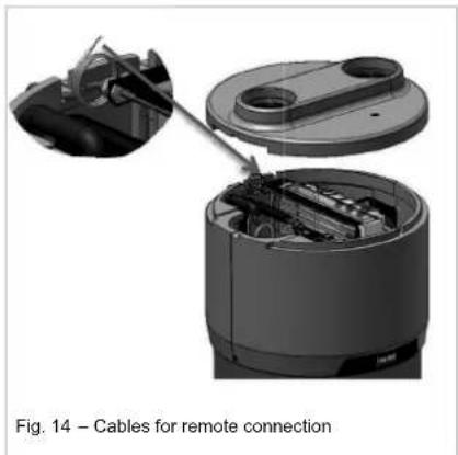
As regards links to digital inputs, the equipment is provided with an additional 4-core cable that has already been linked to circuit board of the user interface (placed inside the equipment Fig. 14). The remote links to any energy systems must be carried out by a qualified installer (junction boxes, terminals and connection cables).
The following illustrations show an example of a remote link (Fig. 13 and Fig. 13a).
To access the 4-core cable for remote connection it is necessary to remove the upper cover of the boiler (see paragraph 9.1 Fig. 18), and take the cable outside through the dedicated opening, that is already present on the back cover, as indicated in Fig. 14.
natural_image
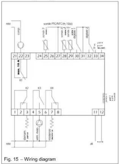
Diagram of a cable assembly showing internal components and connection (no text or symbols)6.7 Wiring diagram
7 Commissioning

WARNING!
Check that the equipment is connected to the earth cable.

WARNING!
Check that the line voltage corresponds to that indicated on the equipment identification plate.
The commissioning procedure must be carried out by performing the following procedures:
- Fill the boiler by acting on the water inlet tap and check that there are no leaks from gaskets and connections. Tighten the bolts or connections where necessary;
- Do not exceed the maximum permitted pressure indicated in the "general technical data" section;
- Check that the water circuit safety equipment is working;
- Connect the plug to the power socket;
- When the plug is inserted, the boiler is in stand-by, the display remains switched off, the power key is illuminated;
- Press the power key (see paragraph ☐), the equipment starts up in the "ECO" mode (default setting) 5 minutes after pressing the key.
8 Operation and use
The management of the device is assigned to a user interface that enables the:
- Setting of the operating mode;
- Modification of the operating parameters;
- Display and management of any emergency situations;
• Verification of the state of resources.

Below, the term "start" intends the switching from the Stand -by to the ON status; the term "switch off" intends the switching from the ON to the Stand -by status.

Below, the term "advanced procedure" refers to particular procedures of the tool described in the paragraphs relating to "advanc ed management".
8.1 The User Interface
The user interface (Fig. 16) allows the verification and the adjustment of the equipment operation. This is equipped with a display and the following keys:
- On/Stand-by key;
- SET key;
- DOWN key;
- UP key.
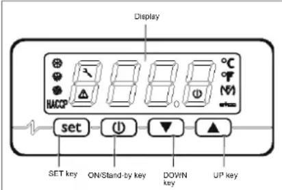
Fig. 16 – User interface
8.1.1 Interface keys and display
8.1.1.1 The ON/Stand-by key
By means of this key it is possible:
• To switch the device on (ON status);
- To switch the device to the Stand-by status (in this status, the instrument can automatically switch on in certain time slots and independently enable the anti-Legionella and defrosting functions.

When the equipment is switched on, it shows the status it was in when it was previously switched off.
8.1.1.2 The [SET] key
By means of this key it is possible to:
• Confirm set choices or values.
8.1.1.3 The [UP] key
By means of this key it is possible to:
- Scroll up the list of the various parameters;
• Increase the value of a parameter.
8.1.1.4 The [DOWN] key
By means of this key it is possible to:
- Scroll down the list of the various parameters;
- Reduce the value of a parameter.
8.1.1.5 The Interface Display
The interface display (Fig. 17) makes it possible to visualise:
• Regulation temperatures;
• Alarm/Error codes;
- Status messages;
• Operating parameters.
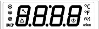
Fig. 17 – User interface display
| Compressor LED | If this is lit: the compressor is active.It this is flashing:The compressor switching on procedure is in progress.The modification of the operating set points is in progress; | |
| Defrosting LED | If this is lit: defrosting is in progress | |
| MF LED | If this is lit: the electric heating element is on | |
| Fan LED | If this is lit: the fan is active | |
| Maintenance LED | If this is lit: maintenance of the air filter is required (if present) | |
| Alarm LED | If this is lit: check the list of alarms and follow the procedure indicated in this manual | |
| Degree Celsius LED | If this is lit: the unit of measurement for temperatures is the degree Celsius | |
| Degree Fahrenheit LED | If this is lit: The unit of measurement for temperatures is the degree Fahrenheit. | |
| On/stand-by LED | If this is lit: the equipment is in the stand-by status.If it is flashing, the equipment has been switched on/off manually during a switching on/off period in a certain timeslot. | |
| HACCP | Not used |
8.1.1.6 Warnings
| Loc | The keyboard is locked (see paragraph 8.1.3.3). |
| dEFr | The defrosting procedure is in progress and it is not possible to enable other functions |
| Anti | The “Anti -Legionella” function is in progress. |
| ObSt | The "Overboost" function is in progress. |
| ECO | The "Economy" function is in progress. |
| Auto | The "Automatic" function is in progress. |
8.1.2 Operating logic
8.1.2.1 Operating modes
The equipment foresees the following operating modes:
• AUTOMATIC operating mode:
This mode mainly uses the renewable energy of the heat pump as a support measure, the electric heating elements can be enabled; these latter heating sources are enabled if the water temperature is below a certain level, or in the event that a temperature exceeding SP5 parameter is required;
• ECONOMY operating mode:
This mode uses only the renewable energy of the heat pump without ever enabling the electric heating elements. It takes longer to enable but it has considerable energy saving characteristics;
• OVERBOOST operating mode:
This mode makes it possible to heat water rapidly by using both the heat pump and the electric heating elements. This function can be manually enabled when the temperature of the water inside the storage tank is lower than SP3 parameter. At the end of the heating process, the function is automatically disabled and the equipment is automatically restored to the Automatic or Economy mode depending on which of these functions was previously set by the user;
• ANTI-LEGIONELLA operating mode
This function is used as an anti-bacterial treatment by increasing the temperature of the water to 60^ C. This function is periodically and, in any case, automatically enabled every 30 days, regardless of the operating mode enabled;
• DEFROSTING mode
This function is necessary in order to eliminate the frost deposits that form and which prevent heat transmission. This function is automatically enabled when the equipment is operated at low environmental temperatures.

When the equipment is switched on for the first time, it is pre-set in the ECO (Economy) mode with a water set point of 55^ with the aim of guaranteeing the best possible energy saving function with the support of only renewable energy sources. Please note that the use of such function guarantees the user an average energy saving of approx. 70% when compared to a normal electric boiler.
8.1.3 Basic management
8.1.3.1 Manual switching on /off of the equipment
- Keep the key pressed for 1 second: the on/stand-by LED will switch off/on.
- The equipment can be switched on/off also in certain timeslots; the parameters HOn and HOF can be seen (paragraph 8.1.3.6).

Manual switching on/off always has the priority over the timeslot operating mode.

If the keyboard has been locked (paragraph 8.1.3.3) or an advanced procedure is in progress, it will not be possible to carry out the normal switching on/off of the equipment.

Every time the equipment is switched on, a series of internal inspections are carried out before the heat pump is enabled. Such condition is reported by means of the flashing of the compressor indicator light. Once the verification period has passed (approx. 5 minutes) the indicator light remains lit and this indicates that the unit is switched on.
8.1.3.2 Change of operating mode (AUTOMATIC, ECONOMY and OVERBOOST)
8.1.3.2.1 AUTOMATIC operating mode
To manually start the AUTOMATIC mode, carry out the following procedure:
- Make sure that the keyboard is not locked (paragraph 8.1.3.3) and that no other advanced procedure is in progress;
- Press per the key for 1 second, "Auto" starts to flash;
- Press the key again to confirm and start the AUTOMATIC operating mode.
To exit the procedure: - Press the key to exit this procedure without changing the mode.
8.1.3.2.2 ECO (economy) operating mode
To manually start the ECO operating mode, carry out the following procedure:
- Make sure that the keyboard is not locked (paragraph 8.1.3.3), that no other advanced procedure is in progress and that the equipment is not in the Overboost operating mode;
- Press flash; thkey for 1 second, "ECO" starts to
- Press the key again to confirm and start the ECONOMY operating mode.
To exit the procedure: - Press the key to exit this procedure without changing the mode.
8.1.3.2.3 OVERBOOST operating mode
To manually start the OVERBOOST operating mode, carry out the following procedure:
- Make sure that the keyboard is not locked (paragraph 8.1.3.3) and that no other advanced procedure is in progress;
- Press the key for 1 second, either "ECO" or "Auto" starts to flash;
- Press the ▲ or ▼ keys until "ObSt" flashes on the display;
- Press the key again to confirm and start the OVERBOOST operating mode.
To exit the procedure: - Press the key to exit this procedure without changing the mode.
8.1.3.3 Keyboard locking/unlocking
To lock the keyboard, carry out the following procedure:
- Make sure that no other advanced procedure is in progress;
- Keep the and the keys pressed for 1 second: "Loc" will be shown on the display for 1 second.
If the keyboard is locked, it will not be possible to carry out any kind of operation on the display interface.

By pressing any key, "Loc" will be shown for 1 second on the display.
To unlock the keyboard:
- Keep the and the keys pressed for 1 second: "UnL" will be shown for 1 second on the display.
8.1.3.4 Temperature setting in the ECO operating mode (SP1)
- Make sure that the keyboard is not locked (paragraph 8.1.3.3) and that no other advanced procedure is in progress;
- Press and release the set key: "SP1" will be shown on the display;
- Press and release the key: the compressor LED will flash;
-
Press either the or the key within 15 seconds; parameters r3, r4 and r5 can be seen;
-
Press and release the keyor do not carry out any other operations for 15 seconds: the compressor LED will switch off;
- Press and release the key To exit the procedure before its completion:
- Do not carry out any operations for 15 seconds (any changes will be saved).
8.1.3.5 Temperature setting in the Automatic mode (SP2)
- Make sure that the keyboard is not locked (paragraph 8.1.3.3) and that no other advanced procedure is in progress;
- Press and release the key SP1" will be shown on the display;
- Press either the ▲ or the ▼ key until "SP2" is shown on the display;
- Press and release the key, the compressor LED will flash;
- Press either the or the key within 15 seconds; parameters r1, r2 and r5 can also be seen;
- Press and release the keyor do not carry out any other operations for 15 seconds: the compressor LED ( ) will switch off;
- Press and release the key
To exit the procedure before its completion:
- Do not carry out any operations for 15 seconds (any changes will be saved).
8.1.3.6 Timeslot settings for the switching on/off of the equipment

N.B.
Before proceeding with the timeslot settings, set day and real time as described in paragraph 8.1.3.14.
To start the procedure:
• Make sure that the keyboard is not blocked and that no other advanced procedure is in progress;
- Press and release the key-SP1" will be shown on the display.
To set the first timeslot:
- Press and release either the or the key within 15 seconds to select "HOn1" (first switching on time) and/or "HOf1" (first switching off time); select "HOn2" and "HOF2" for the second switching on/off time;
-
Press and release the key
-
Press and release either the or the key and within 15 seconds;
- Press and release the key or do not carry out any other operations for 15 seconds.
To associate a time slot to a certain day of the week:
- After the previous procedure has been carried out, press either the ▲ the key and then let it go within 15 seconds in order to select "Hd1" (switch on time for day 1, or rather Monday) and/or "Hd2...7" (switching on time for days 2-7, or rather Tuesday-Sunday);
- Press and release the key;
- Press and release either the or the key within 15 seconds in order to select "1" (the first switch on/off time) or "2" (the second switch on/off time);
- Press and release the key or do not carry out any other operations for 15 seconds.
To exit the procedure before its completion:
- Do not carry out any operations for 15 seconds (any changes will be saved) or press the key and then let it go.

Carefully evaluate enabling of time slot operation in order to avoid malfunctions caused by users.
8.1.3.7 Display of the operating status
- Make sure that the keyboard is not locked (paragraph 8.1.3.3) and that no other advanced procedure is in progress;
- Press and release the key Auto/ECO/Obst/Anti will be displayed for 3 seconds depending on the current active operative status.
8.1.3.8 Silencing of the alarm sound
To silence the alarm, carry out the following procedure:
- Make sure that no other advanced procedure is in progress;
- Press any key once.

N.B. The following instructions are reserved for specialised technical assistance personnel.
8.1.3.9 Different operating mode start conditions
Each operating mode must comply with precise conditions in order to be enabled:
- AUTOMATIC operating mode The condition in order to enable the start of this function is as follows: lower probe< SP2 – r0 (hysteresis);
- ECO operating mode The condition in order to enable the start of this function is as follows: lower probe< SP1 - r0 (hysteresis);
• OVERBOOST operating mode The condition in order to enable the start of this function is as follows: lower probe< SP3 and upper probe< SP3. Once a temperature exceeding SP3 has been detected, the Overboost operating mode terminates and the previously set operative mode is restored.
8.1.3.10 The display
If the equipment is in the "ON" status, during normal operation, the display will show the established temperature by means of parameter P5:
- If P5 = 0, the display will show the temperature of the upper part of the boiler;
- If P5 = 1, the display will show the active working set point;
- If P5 = 2, the display will show the temperature of the lower part of the boiler;
- If P5 = 3, the display will show the temperature of the evaporator;
- If the equipment is in the "stand-by" status, the display will be switched off.
8.1.3.11 Alarms

NOTE
In case of "Utl" alarm (fault of the fan), in addition to the display visualization, the equipment emits an acoustic signal that can be switched off pressing any key on the controller. The alarm it is never canceled unless the equipment is switched off or put in stand-by. The heat pump working mode is automatically disabled and the one with electric resistance is activated in order to ensure the continuity of the warm water supply.

PLEASE NOTE!
In case of "UtL" alarm it is necessary to contact the technical assistance.
| AL | Minimum temperature alarm |
| Solution:- Check the temperature associated with the alarm;- Parameters displayed: A0, A1, A2 and A11.Main consequences:- The equipment will continue to work as normal | |
| AH | Maximum temperature alarm |
| Solutions:- Check the temperature associated with the alarm;- Parameters displayed: A3, A4, A5 and A11.Main consequences:- The equipment will continue to work as normal. | |
| id | Digital input alarm |
| Solutions:- Check the causes that originated the input activation (possible short circuit in signal cables)- See parameters: i0; i1 and i2;Main consequences:- Compressor will be switched off;- Defrosting will not be activated. | |
| iSd | Blocked equipment alarm |
| Solutions:- Check the causes that originated the digital input activation- See parameters: i0; i1; 18 and i9- Switch the equipment off and then back on again or disconnect the equipment from the mains power supply.Main consequences:- Compressor will be switched off;- Defrosting will be never activated. | |
| FIL | Ventilation filter check alarm |
| Solutions:- Check how clean the filter is (to switch off the alarm message, press any key on the display) | |
| UtL | Probable fan fault |
| Solutions:- See parameters SP10 and C14- Check the fan conditionsMain consequences:- Compressor and fan are switched off;- Water heating occurs using only the electric resistance. |

When the cause of the alarm has been removed, the normal operation of the equipment is restored.
8.1.3.12 Error messages
| Pr1 | Error in probe in upper part of the boiler |
| Solutions:- Check that the type of probe is in conformity with parameter P0 settings;- Check the probe is intact;- Check the equipment-probe connection;- Check the temperature of the upper part of the boiler.Main consequences:- The equipment stops working. | |
| Pr2 | Error in probe in lower part of the boiler |
| Solutions:- The same as the previous situation but relating to the probe in the lower part of the boiler.Main consequences:- The equipment stops working. | |
| Pr3 | Error in evaporator probe |
| Solutions:- The same as the previous situation but relating to the evaporator probe.- The equipment stops working. |

When the cause of the alarm has been removed, the normal operation of the equipment is restored.
8.1.3.13 Defrosting
Defrosting can be enabled in the following way:
- Automatically, when the temperature of the evaporator is below that established in parameter d17 (only if P4 has a value other than 0);
In any case, between one defrosting procedure and another, the compressor must have been left switched on for a period either longer than or equal to d18 minutes. Otherwise the request to enable the defrosting procedure will not be accepted.
If P4 = 1, d2 represents the temperature of the evaporator, above which the defrosting procedure is terminated. Vice versa, if P4 = 0 or P4 = 2, parameter d2 is not taken into consideration.
If during the defrosting procedure the evaporate or probe is above the threshold set by means of parameters d2 and P4 = 1, the request to enable the defrosting procedure is not accepted.
The defrosting procedure consists of three stages:
- Defrosting stage: Parameter d3 establishes the maximum duration of the stage. Output status:
- The compressor is active if d1 = 1, otherwise it is switched off;
- The defrosting relay is active if d1 = 0 or d1 = 1 , otherwise it is switched off;
- The fans are switched on if d1 = 2 , otherwise they are switched off.
-
Dripping stage: Parameter d7 establishes the duration of the stage. Output status:
-
The compressor is switched off;
- The defrosting relay is active if d1 = 0 or d1 = 1, otherwise it is switched off;
-
The fans are switched off.
-
Drying stage. Parameter d16 establishes the duration of the stage. Output status:
- The compressor acts according to parameter d8;
- The defrosting relay is active if d1 = 0 or d1 = 1 , otherwise it is switched off;
- The fans are switched off.

If the "Anti-Legionella" or the "Overboost" functions are in progress, the defrosting procedure will not be enabled.
8.1.3.14 Day and real time settings
- Make sure that the keyboard is not locked (paragraph 8.1.3.3) and that no other advanced procedure is in progress;
- Press and release the key the display will show the first code available;
- Press and release either the or the key until "rtc" is shown;
The day is displayed as 1...7 (number 1 corresponding to Monday).
To change the day of the week:
- Press and release the key the display will show "dd" followed by the two numbers representing the day;
- Press and release either the or the key within 15 seconds.
To change the time:
- Press and release the key while changing the day of the month: the display will show "hh" followed by the two numbers representing the time (Time is shown in the 24 hr. format);
- Press and release either the or the key within 15 seconds.
To change the minutes:
- Press and release the key while changing the time: the display will show "nn" followed by the two numbers representing the minutes;
- Press and release either the or the key within 15 seconds;
- Press and release the key or do not carry out any operations for 15 seconds;
To exit the procedure:
- Press and release the key until the display shows the temperature established by parameter P5 or do not carry out any operations for 60 seconds.
Alternatively:
- Press and release the key

To set operations within timeslots, it is necessary to have carried out the settings relating to the day and the real time beforehand.
8.1.3.15 Configuration parameter settings
To carry out the procedure:
- Make sure that the keyboard is not locked (paragraph 8.1.3.3) and that no other advanced procedure is in progress;
- Keep the and the keys pressed for 4 seconds: the display will show "PA" (password);
- Press and release the key
- Press and release either the or the key within 15 seconds to set "-19" on the display;
- Press and release the key or do not carry out any other operations for 15 seconds;
- Keep the and the keys pressed for 4 seconds: the display will show the first parameter "SP1".
To select a parameter:
- Press and release either the or the key.
To change a parameter:
- Press and release the key
- Press either the or the key to either increase or reduce the parameter value (within 15 seconds);
- Press and release the key or do not carry out any operations for 15 seconds.
To exit the procedure:
- Keep the and the keys pressed for 4 seconds or do not carry out any operations for 60 seconds (any changes will be saved).

Switch the equipment off and then back on again to make the changes made to the parameters effective.
8.1.3.16 Restoring default factory settings
To carry out the procedure:
- Ensure that the keyboard is not locked (paragraph 8.1.3.3) and that no other advanced procedure is in progress;
- Keep the and the keys pressed for 4 seconds: the display will show "PA" (password);
- Press and release the key
- Press and release either the or the key within 15 seconds to set "149";
- Press and release the key or do not carry out any operations for 15 seconds;
- Keep the and the pressed for 4 seconds: the display will show "dEF";
- Press and release the key
- Press and release either the 15 seconds to set "1";
- Press and release the keycr do not carry out any other operations for 15 seconds: the display will show "dEF" flashing for 4 seconds, after which the equipment will exit the procedure;
- Disconnect the equipment from the mains power supply.
To exit the procedure before its completion:
- Keep the and the key pressed for 4 seconds during the procedure (or rather before setting "1": the restoring of default factory settings will not be carried out).
8.1.3.17 TOTAL OF THE COMPRESSOR OPERATING HOURS
8.1.3.17.1 General information
The equipment is capable of memorising up to 9,999 compressor operating hours, if the number of hours exceeds "9,999" it flashes.
8.1.3.17.2 Display of compressor operating hours
- Make sure that the keyboard is not locked (paragraph 8.1.3.3) and that no other advanced procedure is in progress;
- Press and release the key the display will show "Pb1";
- Press and release either the or the key to select "CH";
- Press and release the key
To exit the procedure:
- Press and release the key or do not carry out any other operation for 60 seconds.
Alternatively:
- Press and release the key
8.2 Particular operations
The product has a fan speed control system that increases the speed of the same, when the ambient temperature drops to below -1^ , at higher temperatures, the fan maintains a lower speed in order to reducing the noise of the equipment.
The equipment is also provided with a verification system of the environmental conditions concerning the temperatures of the external incoming air. The below described function is necessary to avoid the equipment working with the heat pump mode out of specification, which may cause faults to the compressor and the consequent interruption of the functionality.
By every start, the fan is activated for a time set up by parameter C12 corresponding to 1 minute. After this time, the system measures the incoming air temperature. If the temperature is equal to or lower than parameter SP9 (-7°C), then the conditions for the activation of the heat pump unit are not met, therefore the electric resistance is activated. The heating-up process continues with the help of the electrical resistance until the set point established with the ongoing active cycle is reached.
The system verifies cyclically (every 120 minutes) the environmental conditions and activates the heat pump mode only when these conditions are adequate for its operation.
8.2.1 List of equipment parameters
| Parameter description | Code | U.M. | Min | Max | Default | Notes |
| Password (shadow) | PA | 0 | Function reserved for specialised technical staff | |||
| H2O Set HOT economy cycle | SP1 | °C/°F | r3 | r4 | 55.0 | |
| H2O Set HOT automatic cycle | SP2 | °C/°F | r1 | r2 | 55.0 | |
| H2O Set COLD | SP3 | °C/°F | 10.0 | r2 | 45.0 | |
| H2O Set for heat pump stop | SP5 | °C/°F | r1 | 70.0 | 62.0 | |
| H2O Set for the enabling of photovoltaic supplement | SP6 | °C/°F | 40.0 | 100.0 | 62.0 | |
| H2O Set ANTI-FREEZE | SP7 | °C/°F | 0 | 40 | 10 | |
| Set point solar thermal cycle | SP8 | °C/°F | 0 | 100.0 | 40 | |
| Set cold evaporator | SP9 | °C/°F | -25.0 | 25.0 | -7.0 | |
| Set damaged evaporator | SP10 | °C/°F | -50.0 | 25.0 | -25.0 | |
| Upper probe calibration | CA1 | °C/°F | -25.0 | 25.0 | 2.0 | |
| Lower probe calibration | CA2 | °C/°F | -25.0 | 25.0 | 0.0 | |
| Evaporator probe calibration | CA3 | °C/°F | -25.0 | 25.0 | 0.0 | |
| Probe type | P0 | ---- | 0 | 1 | 1 | 0 = PTC1 = NTC2 = PT1000 |
| Decimal point | P1 | ---- | 0 | 1 | 1 | 1 = Display decimal point per temperature |
| Unit of measurement | P2 | ---- | 0 | 1 | 0 | 0 = °C1 = °F |
| Function associated with the evaporator probe | P4 | ---- | 0 | 2 | 2 | 0 = Disabled1 = Defrosting start-stop2 = Defrosting start |
| Local display data | P5 | ---- | 0 | 3 | 0 | 0 = Upper probe1 = Operative set point2 = Lower probe3 = Evaporator probe |
| Remote display data | P6 | ---- | 0 | 3 | 0 | 0 = Upper probe1 = Operative set point2 = Lower probe3 = Evaporator probe |
| Display data refresh time specified in tenths of a second | P8 | 1/10 sec | 0 | 250 | 5 | |
| Work set hysteresis | r0 | °C/°F | 0.1 | 30.0 | 7.0 | |
| Minimum auto cycle set point | r1 | °C/°F | 10.0 | r2 | 40.0 | |
| Maximum auto cycle set point | r2 | °C/°F | r1 | 100.0 | 70.0 | |
| Minimum economy cycle set point | r3 | °C/°F | 10.0 | r4 | 40.0 | |
| Maximum economy cycle set point | r4 | °C/°F | r3 | 100.0 | 56.0 | |
| Work set change block | r5 | ---- | 0 | 1 | 0 | 1 = It is not possible to change the set point; it can only be seen |
| Delay in equipment start-up | C0 | min | 0 | 240 | 5 | Compressor protections |
| Delay as from last ON | C1 | min | 0 | 240 | 5 | |
| Delay as from last OFF | C2 | min | 0 | 240 | 5 | |
| Minimum ON time | C3 | sec | 0 | 240 | 0 | |
| Number of compressor operating hours required for maintenance | C10 | h | 0 | 9999 | 1000 | 0 = Function excluded |
| Delay air temperature sample taking for cold evaporator test | C11 | min | 0 | 999 | 120 | |
| Minimum delay between fan start-up and compressor activation for incoming air temperature check | C12 | min | 0 | 240 | 1 | |
| Timeout solar thermal cycle | C13 | min | 0 | 240 | 20 | |
| Delay for damaged fan check | C14 | min | -1 | 240 | 20 | -1 = disabled function |
| Type of defrosting | d1 | ---- | 0 | 2 | 1 | 0 = With heating element1 = With hot gas2 = With compressor stopped |
| Evaporator temperature to conclude defrosting procedure (only if P4=1) | d2 | °C/°F | -50.0 | 50.0 | 30 | |
| Maximum duration of defrosting procedure | d3 | min | 0 | 99 | 8 | |
| Automatic defrosting start threshold (evaporator temperature) | d17 | °C/°F | -50.0 | 50.0 | -2.0 | |
| Minimum compressor start up time to start defrosting procedure | d18 | min | 0 | 240 | 60 | |
| Minimum level probe alarm(only AL1 warning) | A0 | ---- | 0 | 2 | 0 | 0 = Upper probe1 = Lower probe2 = Evaporator probe |
| Minimum alarm set (only AL1 warning) | A1 | °C/°F | 0.0 | 50.0 | 10.0 | |
| Type of minimum level alarm delay(only AL1 warning) | A2 | ---- | 0 | 1 | 0 | 0 = Disabled1 = Absolute |
| Maximum level probe alarm (only AH warning) | A3 | ---- | 0 | 2 | 0 | 0 = Upper probe1 = Lower probe2 = Evaporator probe |
| Maximum alarm set(only AH warning) | A4 | °C/°F | 0.0 | 199.0 | 90.0 | |
| Type of maximum level alarm delay(only AH warning) | A5 | ---- | 0 | 1 | 0 | 0 = Disabled1 = Absolute |
| Minimum level AL1 alarm delay due to equipment start-up (only warning) | A6 | min | 0 | 240 | 120 | |
| AL1 and AH temperature alarm delays(only warning) | A7 | min | 0 | 240 | 15 | |
| Alarm hysteresis | A11 | min | 0.1 | 30.0 | 2.0 | |
| Heating element start-up interval (Anti-Legionella) | H0 | days | 0 | 99 | 30 | |
| Anti-Legionella function set | H1 | °C/°F | 10.0 | 199.0 | 60.0 | |
| Duration of Anti-Legionella function | H3 | min | 0 | 240 | 2 | |
| Solar thermal input enabling (Digital 1) | i0 | ---- | 0 | 2 | 2 | 0 = Input disabled1 = Pressure input2 = Digital 1 input |
| Type of solar thermal input contact | i1 | ---- | 0 | 1 | 0 | 0 = Active if contact is closed1 = Active if contact is open |
| High/low pressure end compressor protection | i2 | min | 0 | 120 | 0 | |
| Photovoltaic input enabling (Digital 2) | i3 | ---- | 0 | 1 | 1 | 0 = Input disabled1 = Input enabled |
| Type of photovoltaic input contact (Digital 2) | i4 | ---- | 0 | 1 | 0 | 0 = Active if contact closed1 = Active if contact open |
| Number of digital input alarms per equipment block | i8 | ---- | 0 | 15 | 0 | |
| Time for digital input alarm counter reset | i9 | min | 1 | 999 | 240 | |
| Buzzer enabling | u9 | ---- | 0 | 1 | 1 | 0 = Buzzer disabled1 = Buzzer enabled |
| Switching on time for Monday | Hd1 | ---- | 1 | 2 | 1 | 1 = HOn1-HOF12 = HOn2-HOF2 |
| Switching on time for Tuesday | Hd2 | ---- | 1 | 2 | 1 | 1 = HOn1-HOF12 = HOn2-HOF2 |
| Switching on time for Wednesday | Hd3 | ---- | 1 | 2 | 1 | 1 = HOn1-HOF12 = HOn2-HOF2 |
| Switching on time for Thursday | Hd4 | ---- | 1 | 2 | 1 | 1 = HOn1-HOF12 = HOn2-HOF2 |
| Switching on time for Friday | Hd5 | ---- | 1 | 2 | 1 | 1 = HOn1-HOF12 = HOn2-HOF2 |
| Switching on time for Saturday | Hd6 | ---- | 1 | 2 | 2 | 1 = HOn1-HOF12 = HOn2-HOF2 |
| Switching on time for Sunday | Hd7 | ---- | 1 | 2 | 2 | 1 = HOn1-HOF12 = HOn2-HOF2 |
| Time for first switch on timeslot | HOn1 | ---- | 00:00 | 23.59 | --;-- | --;-- = Function excluded |
| Time for first switch off timeslot | HOF1 | ---- | 00:00 | 23.59 | --;-- | --;-- = Function excluded |
| Time according to timeslot switch on | HOn2 | ---- | 00:00 | 23.59 | --;-- | --;-- = Function excluded |
| Time according to timeslot switch off | HOF2 | ---- | 00:00 | 23.59 | --;-- | --;-- = Function excluded |
| Equipment address | LA | ---- | 1 | 247 | 247 | |
| Baud Rate | Lb | ---- | 0 | 3 | 2 | 0 = 24001 = 48002 = 96003 = 19200 |
| Parity | LP | ---- | 0 | 2 | 2 | 0 = NONE1 = ODD2 = EVEN |
| RESERVED | E9 | ---- | 0 | 2 | 0 | |
9 Maintenance and cleaning

WARNING!
Any equipment repair must be performed by qualified personnel. Improper repairs can put the user in serious danger. If your equipment needs to be repaired, please contact the technical assistance service.

WARNING!
Before attempting any maintenance operation, make sure that the equipment is not and cannot be accidentally connected to the power supply. Therefore, disconnect the equipment from the mains power supply before carrying out any maintenance or cleaning activities.
9.1 Resetting of safety equipment
The device is equipped with a safety thermostat. When manually reset, the equipment is tripped in case of over-heating.
In order to reset the protection it is necessary to:
x Disconnect the device from the mains power supply;
x Remove any air ducts (see paragraph 6.1.1);
x Remove the upper cover by undoing the appropriate locking screws (Fig. 18);
x Manually reset the tripped safety thermostat from the top (Fig. 19). In the event of the tripping, the central pin of the thermostat sticks out by approximately 4 mm;
x Reassemble the upper cover that was previously removed.
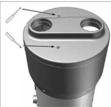
natural_image
3D mechanical component with cylindrical and flanged features, no visible text or symbolsFig. 18 – Removal of upper cover
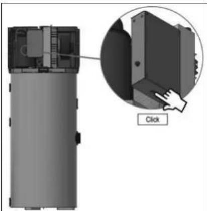
natural_image
Diagram of a device with an inset showing a close-up of a component, labeled 'Click' (no text or symbols on the diagram itself)Fig. 19 – Resetting the Safety thermostat

WARNING!
The tripping of the safety thermostat can be caused by a fault linked to the control board or by the absence of water inside the tank.

WARNING!
Carrying out repair operations on parts that perform safety functions jeopardises the safe operation of the equipment. Substitute the faulty elements only with original spare parts.

N.B.
The intervention of the thermostat excludes the operation of the electric heating elements but not the heat pump system within the permitted operating limits.
9.2 Quarterly inspections
x Visual inspection of the general conditions of the equipment systems as well as the absence of leaks;
x Inspection of the ventilation filter (see paragraph 9.4).
9.3 Annual inspections
x Inspection of the tightness of bolts, nuts, flanges and water supply connections that may have been loosened by vibration;
x Check the state of integrity of the magnesium anodes (see paragraph 9.5).
9.4 Cleaning of the ventilation filter
In the upper part of the equipment there is a ventilation filter. This must be periodically cleaned in order to maintain the perfect efficiency of the system.
After every 1000 hours of operation, the display of the equipment shows the "FiL" alarm that indicates the need to check the cleanliness of the filter.
To remove the filter, it is necessary to grab it with the fingers from the dedicated side opening and pull it outside (Fig. 20).
The filter can be cleaned with rinsing, water gush or slamming. Since the filter is made of stainless steel, it does not need to be periodically substituted.
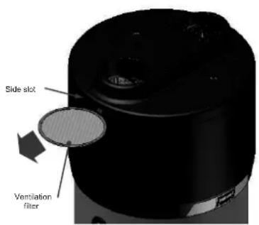
Fig. 20 – Details of the ventilation filter

N.B.
The filter obstruction reduces the heat pump system performance causing insufficient, or, even total lack of ventilation.
9.5 Magnesium anodes
The magnesium anode (Mg), also called "sacrificial" anode, avoids any parasitic currents that are generated inside the boiler that can trigger corrosion processes on the device surface.
In fact, magnesium is a metal with a lower electrochemical potential when compared to the material that lines the inside of the boiler, therefore it first attracts the negative charges that form with the heating of the water and that cause it to corrode. Therefore, the anode “sacrifices” itself by corroding instead of the tank. The boiler has two anodes, one that has been mounted in the lower part and another in the upper part of the tank (the area that is most subject to corrosion).
The integrity of the magnesium anodes must be checked at least every two years (even better if checked on an annual basis). The operation must be carried out by qualified personnel.
Before performing the inspection, it is necessary to:
- Close the cold water input supply;
• Empty the water from the boiler (see paragraph 9.6); - Unscrew the upper anode and check its state of corrosion, if more than 30% of the anode surface is corroded then it is necessary to replace it;
- Carry out the same operation for the lower anode.
- The anodes have appropriate sealing gaskets, in order to avoid causing water leaks, it is recommended to use anaerobic sealant for threads compatible for use on sanitary and heating systems. The gaskets must be substituted both in case of inspection as well as the replacement of anodes with new gaskets.
9.6 Emptying the boiler
It is advisable to drain the water from the boiler if the boiler is not in use for a certain period of time, especially in low temperatures.
It is recommended to drain the water from the boiler if the boiler remains stationary for a certain period of time, especially at low temperatures.
Before draining the water, the appliance must be switched off and disconnected from the mains. Proceed as follows to drain the water from the boiler: switch off the appliance and disconnect the power supply cable from the mains, close the water shut-off valve (see 2 fig. 8 paragraph 6.4), operate the drain tap (see 5 fig. 8 paragraph 6.4). To facilitate the flow of water to the drain it is recommended (if it is not already present), to install a hose connector on the drain tap.

N.B.
It is important to empty the system in case of low temperatures in order to avoid the water freezing.
9.7 Inspection of the electrical resistance compartment
In case of access to the resistance compartment, refit the cover with the arrow pointing upwards
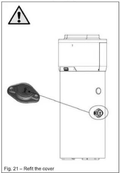
10 Troubleshooting
In case of problems of equipment performance, without the occurrence of any of the alarms or errors described in the relative paragraphs, it is advisable to check to see if the problem can be easily solved by checking the possible solutions specified in the table below prior to seeking technical assistance.
| Problem | Possible causes |
| The heat pump does not work | There is no electricity;The plug is not correctly inserted in the socket. |
| The compressor and/or the fan do not work | The set safety period of time has not finished;The scheduled temperature has been reached. |
| The heat pump continuously switches itself on and off | Wrong programming of the parameters/setpoint and/or hysteresis values. |
| The heat pump remains continuously switched on and does not switch off | Wrong programming of the parameters/set point and/or hysteresis values. |
| The electric heating element does not switch on | Your intervention is not required |

WARNING!
In the event that the operator does not succeed in solving the problem, switch off the equipment and seek technical assistance specifying the device model purchased.
11 Disposal
At the end of their device lifecycle, the heat pumps will be disposed of in conformity with the applicable regulations.

WARNING!
This equipment contains greenhouse fluorinated gas included in the Kyoto protocol. The maintenance and disposal operations must only be carried out by qualified personnel.
INFORMATION TO USERS
Pursuant to Directives 2011/65/EU and 2012/19/EU, relating to the reduction of the use of hazardous substances in electric and electronic equipment as well as waste disposal.
The symbol of the barred wheelie-bin that can be seen either on the equipment or its packaging indicates that the device must be collected separately from other waste at the end of its lifecycle.
At the end of the device lifecycle, the user must therefore take the equipment to suitable separate collection centres for electronic and electro-technical waste, or to return it to the dealer upon purchasing another equivalent device, at the ratio of one to one.
The adequate separate waste collection relating to the subsequent sending of the discontinued equipment for recycling, treatment and/or environmentally-compatible disposal, contributes towards avoiding possible negative effects on both the environment and health; it also encourages the reuse and/or
recycling of materials of which the equipment is made.
The unlawful disposal of the device by the user leads to the application of the administrative penalties foreseen by applicable legislation.
The main materials that are used in the production of the equipment are as follows:
- Steel:
Magnesium; - Plastic;
Copper; - Aluminium;
• Polyurethane.
12 Product fiche
| Descriptions | u.m. | EKHH2E200AAV3 | EKHH2E260AAV3 | EKHH2E260PAAV3 | EKHH2E200BAV33 |
| Declared load profile | L | XL | |||
| Water heating energy efficiency class under average climate conditions | A+ | ||||
| Water heating energy efficiency in % under average climate conditions | % | 123 | 127 | 127 | |
| Annual electricity consumption in kWh under average climate conditions | kWh | 835 | 1323 | 1323 | |
| Thermostat temperature settings of the water heater | °C | 55 | |||
| Sound power level Lwa indoors in dB | dB | 53 | |||
| The water heater is able to work only during off-peak hours | NO | ||||
| Any specific precautions that shall be taken when the water heater is assembled, installed or maintained | See manual | ||||
| Water heating energy efficiency in % under colder climate conditions | % | 94 | 92 | 92 | |
| Water heating energy efficiency in % under warmer climate conditions | % | 135 129 129 149 | |||
| Annual electricity consumption in kWh under colder climate conditions | kWh | 1091 1826 | 1826 936 | ||
| Annual electricity consumption in kWh under warmer climate conditions | kWh | 756 1296 | 1296 688 | ||
| Sound power level Lwa outdoors in dB | dB | 52 | |||
L
136
752
109
INHALTSVERZEICHNIS
6.6.1 Femanschlüsse....21
GEFAHR: STROMSCHLAGGEFAHR
GEFAHR: EXPLOSIONSGEFAHR
GEFAHR: EXPLOSIONSGEFAHR
GEFAHR: STROMSCHLAGGEFAHR
natural_image
3D rendering of a cylindrical mechanical component with mounting holes and housing (no text or symbols visible)natural_image
Illustration of a mechanical device with a worker adjusting its part, accompanied by two checkmarks (no text or symbols present)
ACHTUNG!
natural_image
Technical illustration of industrial cylindrical components with cross-bracing, plus a worker inspecting a component (no text or symbols)4 Aufbau
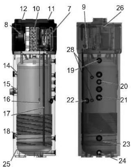
6.4 Hydraulikanschlüsse
6.6.1 Fernanschlüsse
natural_image
Line drawing of a rectangular electrical cabinet mounted on a brick wall, with a small electrical outlet and power outlet (no text or symbols)natural_image
3D mechanical assembly diagram showing internal components and a close-up of a device (no text or symbols visible)natural_image
3D mechanical component with cylindrical features and mounting holes (no visible text or symbols)natural_image
Blank grid paper with uniform squares, no text or symbols present
natural_image
Blank grid paper with uniform gray squares on white background (no text or symbols)

LISTE DES CONTENUS
5.6 Information on coolant used....14
6 Installation et raccordements .... 14
8.1 Interface usager 23
Législation applicable
3 Manutention et transport
natural_image
3D rendering of a cylindrical mechanical component with mounting holes and housing (no text or symbols visible)natural_image
Illustration of a worker assembling a cylindrical device with checkmarks indicating inspection (no text or symbols present)
ATTENTION!
natural_image
Four identical mechanical components with cross-shaped hatching, shown from top to bottom (no text or symbols)
natural_image
Pure mechanical component diagram without any text, numbers, or symbols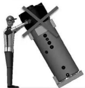
natural_image
Illustration of a worker in safety gear pointing at a large industrial component (no text or symbols visible)
5.6 Information on coolant used
6 Installation et raccordements

ATTENTION!
Fig. 7 – Raccordements hydrauliques
natural_image
Mechanical assembly diagram showing a device being processed into a cylindrical housing (no text or symbols visible)8.1 Interface usager
Fig. 17 – Ecran interface usager
natural_image
3D mechanical component with cylindrical and flanged features, no visible text or symbolsnatural_image
Diagram of a device with an inset close-up showing a button labeled 'Click' (no text or symbols on the diagram itself)WAARSCHUWING: ONTVLAMBAAR
MATERIAAL

VOORZICHTIG
natural_image
3D rendering of a cylindrical mechanical component with mounting holes and housing (no text or symbols visible)natural_image
Illustration of a mechanical device with a worker and a checkmark indicating approval (no text or symbols present)
WAARSCHUWING!
natural_image
Technical illustration of industrial cylindrical components with cross-bracing, plus a worker inspecting a component (no text or symbols)4 Bouwkenmerken

natural_image
3D mechanical component with two circular ports and two side ports, labeled as Fig. 18 – Verwijdering van het deksel bovenaan (no text or symbols on the object itself)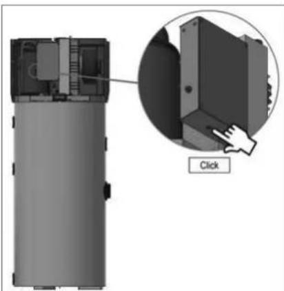
natural_image
Diagram of a device with an inset showing a close-up of a component, labeled 'Click' (no text or symbols on the diagram itself)Fig. 19 – Resetten van de veiligheidsthermostaat

WAARSCHUWING!
natural_image
3D rendering of a cylindrical mechanical component with mounting holes and housing (no text or symbols visible)natural_image
Illustration of a mechanical device with a person adjusting its part, accompanied by two checkmarks (no text or symbols present)
¡ATENCIÓN!
natural_image
Four identical mechanical components with cross-shaped hatching, shown from top to bottom (no text or symbols visible)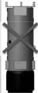
natural_image
Pure mechanical component diagram without any text, numbers, or symbols
natural_image
Illustration of a worker in safety gear pointing at a large industrial machine component (no text or symbols visible)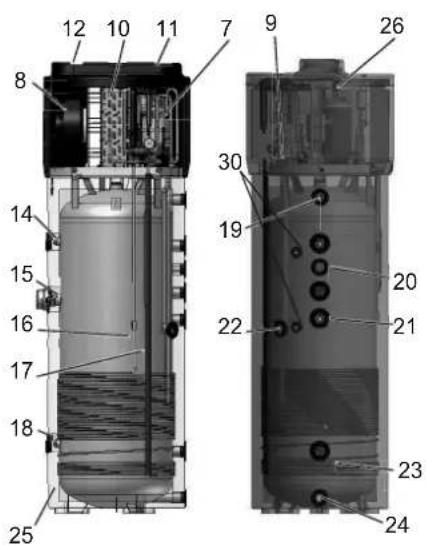
natural_image
Technical line drawing of two electrical installation components mounted on a wall, with brick walls and ground reference (no text or symbols)Fig. 7 – Conexiones hidráulicas
natural_image
Line drawing of a vertical electrical cabinet mounted on a brick wall, with an electrical outlet and power source (no text or symbols)natural_image
3D mechanical assembly diagram showing internal components and a close-up of a device (no text or symbols visible)natural_image
3D diagram of a device with an inset showing a button labeled 'Click' (no text or symbols on the device itself)natural_image
3D rendering of a cylindrical mechanical component with mounting holes and housing (no text or symbols visible)natural_image
Illustration of a worker assembling a cylindrical device with checkmarks indicating inspection or approval (no text or symbols present)
ATTENZIONE
natural_image
Four identical mechanical components with cross-shaped hatching, shown from top to bottom (no text or symbols)
natural_image
Pure mechanical component diagram without any text, numbers, or symbols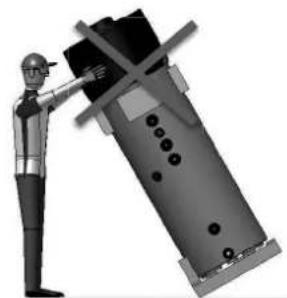
natural_image
Illustration of a worker in safety gear pointing at a large industrial machine component (no text or symbols visible)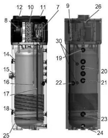
natural_image
Technical line drawing of two electrical grounding systems with pipes and a brick wall (no text or symbols)natural_image
Line drawing of a rectangular electrical cabinet mounted on a brick wall, with a power outlet and wiring (no text or symbols)natural_image
3D mechanical assembly diagram showing internal components with no visible text or symbolsFig. 14 – Cavi per connessione remota
8.1.1.1 Tasto ON / Stand by

natural_image
3D mechanical component with cylindrical features and two protruding rods (no visible text or symbols)natural_image
Diagram of a device with an inset close-up showing a button labeled 'Click' (no text or symbols on the diagram itself)9.3 Controlli annuali
natural_image
Blank grid paper with uniform squares, no text or symbols present
natural_image
Blank grid paper with uniform gray squares on white background (no text or symbols)

ÍNDICE
natural_image
3D rendering of a cylindrical mechanical device with mounting holes and housing (no text or symbols visible)
AVISO!
natural_image
Illustration of a mechanical device with a person adjusting its part, accompanied by two checkmarks (no text or symbols present)
AVISO!
natural_image
Technical illustration of industrial cylindrical components with cross-hatched sections and a worker inspecting a component (no text or symbols)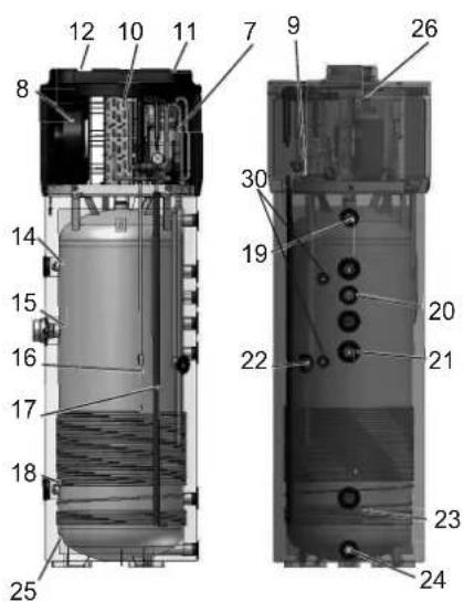
natural_image
Line drawing of a cabinet with electrical wiring and a control panel, set against a brick wall (no text or symbols)Fig. 17 – Ecrã da interface de utilizador

LED do compressor
natural_image
3D mechanical component with cylindrical features and mounting holes (no visible text or symbols)natural_image
Diagram of a device with an inset showing a close-up of a component, labeled 'Click' (no text or symbols on the diagram itself)natural_image
Blank grid paper with uniform squares, no text or symbols present
natural_image
Blank grid paper with uniform gray squares on white background (no text or symbols)

INNEHÅLLSFÖRTECKNING
natural_image
3D rendering of a cylindrical mechanical component with mounting holes and housing (no text or symbols visible)
WARNING!
natural_image
Illustration of a worker assembling a cylindrical device with checkmarks indicating inspection or approval (no text or symbols present)
WARNING!
natural_image
Technical illustration of industrial cylindrical components with cross-bracing, plus a worker inspecting a component (no text or symbols)
4.1 Tekniska egenskaper
natural_image
Technical line drawing of two electrical installation components mounted on a vertical pole, with brick walls and ground anchors (no text or symbols)natural_image
Exploded view of a mechanical device showing internal components and assembly (no text or symbols visible)natural_image
3D mechanical component with two circular ports and two threaded fasteners, shown without any text or symbols.natural_image
Diagram of a device with an inset showing a button labeled 'Click' (no text or symbols on the diagram itself)natural_image
Blank grid paper with uniform squares, no text or symbols present
natural_image
Blank grid paper with uniform gray squares on white background (no text or symbols)

SPIS TREŚCI
natural_image
3D rendering of a cylindrical mechanical component with mounting holes and housing (no text or symbols visible)
OSTRZEŻENIE!
natural_image
Illustration of a mechanical device with a person adjusting its part, accompanied by two checkmarks (no text or symbols present)
OSTRZEŻENIE!
natural_image
Technical illustration of industrial cylindrical components with cross-bracing, plus a worker inspecting a component (no text or symbols)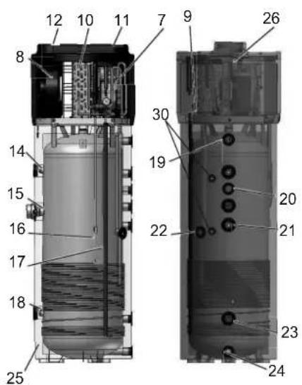
4.1 Dane techniczne
natural_image
Line drawing of a rectangular electrical cabinet mounted on a brick wall, with an electrical outlet and power source (no text or symbols)natural_image
3D cutaway view of a mechanical device showing internal components and assembly (no text or symbols visible)natural_image
3D mechanical component with two circular ports and labeled features, no readable text or symbols beyond technical label (text is part of the diagram)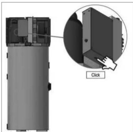
natural_image
3D diagram of a device with an inset showing a button labeled 'Click' (no text or symbols on the device itself)natural_image
Blank grid paper with uniform squares, no text or symbols present
natural_image
Blank grid paper with uniform gray squares on white background (no text or symbols)


natural_image
Two identical empty grid paper sheets with no text, numbers, or symbols


natural_image
Blank grid paper with uniform squares, no text or symbols present
natural_image
Blank grid paper with uniform gray squares on white background (no text or symbols)

DAIKIN EUROPE N.V.
- Installation and user manual
- Domestic Hot Water Heat Pump Monobloc type
- General safety precautions
- About the documentation
- Meaning of warnings and symbols
- DANGER
- DANGER: RISK OF ELECTROCUTION
- DANGER: RISK OF BURNING
- DANGER: RISK OF EXPLOSION
- WARNING
- WARNING: FLAMMABLE MATERIAL
- CAUTION
- NOTICE
- INFORMATION
- Symbol
- Explanation
- For the user
- For the installer
- General
- Refrigerant
- Water
- Electrical
- Glossary
- Introduction
- Products
- Disclaimer
- WARNING!
- Copyright
- Operating principle
- Available versions and configurations
- Handling and transport
- Construction characteristics
- Important information
- Conformity with European regulations
- Degrees of protection provided by enclosures
- Limitations of use
- N.B.
- Operating limits
- Fundamental safety rules
- Information on coolant used
- Installation and connections
- Preparation of the installation site
- Securing to the floor
- Ventilation connection
- Particular installation conditions
- Device mounting and connection
- Water supply connections
- PLEASE NOTE!
- Condense drain connections
- Solar power system
- integration
- Electrical connections
- Remote links
- Remote link mode
- Commissioning
- Operation and use
- The User Interface
- Interface keys and display
- The ON/Stand-by key
- The [SET] key
- The [UP] key
- The [DOWN] key
- The Interface Display
- Operating logic
- Operating modes
- Basic management
- Manual switching on /off of the equipment
- Change of operating mode (AUTOMATIC, ECONOMY and OVERBOOST)
- AUTOMATIC operating mode
- ECO (economy) operating mode
- OVERBOOST operating mode
- Keyboard locking/unlocking
- Temperature setting in the ECO operating mode (SP1)
- Temperature setting in the Automatic mode (SP2)
- Timeslot settings for the switching on/off of the equipment
- Display of the operating status
- Silencing of the alarm sound
- Different operating mode start conditions
- The display
- Alarms
- NOTE
- Defrosting
- Day and real time settings
- Configuration parameter settings
- Restoring default factory settings
- TOTAL OF THE COMPRESSOR OPERATING HOURS
- General information
- Display of compressor operating hours
- Particular operations
- Maintenance and cleaning
- Resetting of safety equipment
- Quarterly inspections
- Annual inspections
- Cleaning of the ventilation filter
- Magnesium anodes
- Emptying the boiler
- Inspection of the electrical resistance compartment
- Troubleshooting
- Disposal
- INFORMATION TO USERS
- INHALTSVERZEICHNIS
- GEFAHR: STROMSCHLAGGEFAHR
- GEFAHR: EXPLOSIONSGEFAHR
- ACHTUNG!
- Aufbau
- Hydraulikanschlüsse
- Fernanschlüsse
- LISTE DES CONTENUS
- Installation et raccordements .... 14
- Manutention et transport
- ATTENTION!
- Installation et raccordements
- Interface usager
- WAARSCHUWING: ONTVLAMBAAR
- MATERIAAL
- VOORZICHTIG
- WAARSCHUWING!
- Bouwkenmerken
- ¡ATENCIÓN!
- ATTENZIONE
- Tasto ON / Stand by
- Controlli annuali
- ÍNDICE
- AVISO!
- INNEHÅLLSFÖRTECKNING
- SPIS TREŚCI
- OSTRZEŻENIE!
Brand : DAIKIN
Model : EKHH2E200BAV33
Category : Boiler