
EKSRDS2A - Boiler DAIKIN - Free user manual and instructions
Find the device manual for free EKSRDS2A DAIKIN in PDF.

| Brand | Daikin |
| Model | EKSRDS2A |
| Category | Solar pump group (pressure station) |
| Dimensions (W x H x D) | 240 x 314 x 220 mm |
| Weight | 5.5 kg |
| Valve material | Brass CW617N |
| Insulation material | Polypropylene EPP |
| System connection | G 3/4 |
| Pump supply | 230 V ~ / 50 Hz |
| Max. installation pressure | 6 bar |
| Max. liquid temperature | 120 °C (temporary 160 °C) |
| Max. ambient temperature | 40 °C |
| Flow meter | 2 - 12 l/min |
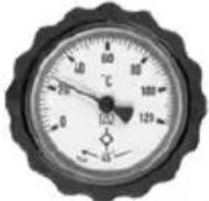
| Thermometer range | 0 - 120 °C |
| Safety valve | 6 bar (membrane) |
| Pressure gauge | 0 - 10 bar, ∅ 63 mm |
| Main functions | Circulation of heat transfer fluid, integrated safety group, air purge, filling/flushing |
| Maintenance | Regular air purge, flow meter check |
| Safety | Overheat protection, thermal shutdown, safety valve |
| Spare parts | Circulation pump, gaskets, expansion vessel, safety valve |
| Warranty | 24 months |
Frequently Asked Questions - EKSRDS2A DAIKIN
User questions about EKSRDS2A DAIKIN
0 question about this device. Answer the ones you know or ask your own.
Ask a new question about this device
Download the instructions for your Boiler in PDF format for free! Find your manual EKSRDS2A - DAIKIN and take your electronic device back in hand. On this page are published all the documents necessary for the use of your device. EKSRDS2A by DAIKIN.
USER MANUAL EKSRDS2A DAIKIN
Operating and installation instructions
Solar pressure station
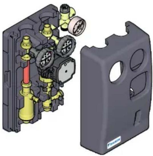
natural_image
3D mechanical assembly diagram showing internal components and a separate gray plastic housing (no text or symbols)Operating and installation instructions Solar pressure station
Operating and installation instructions
Solar pressure station

natural_image
3D mechanical assembly diagram showing internal components and a separate housing (no text or symbols)Operating and installation instructions Solar pressure station
English
Table of contents
1 About these operating instructions.... 3
2 Information on safety.... 4
2.1 Safety messages and hazard categories.... 4
2.2 Intended use 5
2.3 Predictable incorrect application.... 5
2.4 Qualification of personnel 6
2.5 Personal protective equipment 6
2.6 Modifications to the product.... 6
3 Transport and storage....7
4 Product description 8
4.1 Overview 8
4.2 Dimensions 9
4.3 Function 9
4.4 Approvals, conformities, certifications.... 9
4.5 Technical data.... 10
5 Mounting 11
5.1 Preparing mounting.... 11
5.2 Mounting the product 11
5.3 Connecting the product.... 13
5.4 Retrofitting the product.... 14
5.5 Electrical connection.... 14
6 Commissioning.... 16
6.1 Commissioning the product 16
7 Operation 18
7.1 Reading mark at flow meter.... 18
7.2 Venting the system 19
8 Maintenance....20
8.1 Maintenance intervals.... 20
9 Troubleshooting 20
9.1 Replacing the circulation pump.... 21
10 Decommissioning, disposal.... 22
11 Returning the device 22
12 Warranty.... 22
1 About these operating instructions
These operating instructions describe the solar pump assembly
"EKSRDS2A" (also referred to as "product" in these operating instructions).
These operating instructions are part of the product.
- You may only use the product if you have fully read and understood these operating instructions.
- Verify that these operating instructions are always accessible for any type of work performed on or with the product.
- Pass these operating instructions as well as all other product-related documents on to all owners of the product.
- If you feel that these operating instructions contain errors, inconsistencies, ambiguities or other issues, contact the manufacturer prior to using the product.
These operating instructions are protected by copyright and may only be used as provided for by the corresponding copyright legislation. We reserve the right to modifications.
The manufacturer shall not be liable in any form whatsoever for direct or consequential damage resulting from failure to observe these operating instructions or from failure to comply with directives, regulations and standards and any other statutory requirements applicable at the installation site of the product.
2 Information on safety
2.1 Safety messages and hazard categories
These operating instructions contain safety messages to alert you to potential hazards and risks. In addition to the instructions provided in these operating instructions, you must comply with all directives, standards and safety regulations applicable at the installation site of the product. Verify that you are familiar with all directives, standards and safety regulations and ensure compliance with them prior to using the product.
Safety messages in these operating instructions are highlighted with warning symbols and warning words. Depending on the severity of a hazard, the safety messages are classified according to different hazard categories.
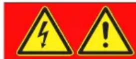
DANGER
DANGER indicates a hazardous situation, which, if not avoided, will result in death or serious injury.
WARNING
WARNING indicates a potentially hazardous situation, which, if not avoided, can result in serious injury or equipment damage.
NOTICE
NOTICE indicates a hazardous situation, which, if not avoided, can result in equipment damage.
In addition, the following symbols are used in these operating instructions:
This is the general safety alert symbol. It alerts to injury hazards or equipment damage. Comply with all safety instructions in conjunction with this symbol to help avoid possible death, injury or equipment damage.
This symbol alerts to hazardous electrical voltage. If this symbol is used in a safety message, there is a hazard of electric shock.
2.2 Intended use
This product may only be used to circulate the following liquids in intrinsically safe, sealed, solar systems:
- Standard heat transfer fluids (solar liquids) suitable for solar systems such as water-glycol mixtures
The integrated safety group assembly serves to secure against excessive pressure.
Any use other than the application explicitly permitted in these operating instructions is not permitted and causes hazards.
Verify that the product is suitable for the application planned by you prior to using the product. In doing so, take into account at least the following:
- All directives, standards and safety regulations applicable at the installation site of the product
- All conditions and data specified for the product
• The conditions of the planned application
In addition, perform a risk assessment in view of the planned application, according to an approved risk assessment method, and implement the appropriate safety measures, based on the results of the risk assessment.
Take into account the consequences of installing or integrating the product into a system or a plant.
When using the product, perform all work and all other activities in conjunction with the product in compliance with the conditions specified in the operating instructions and on the nameplate, as well as with all directives, standards and safety regulations applicable at the installation site of the product.
2.3 Predictable incorrect application
The product must never be used in the following cases and for the following purposes:
• Operation with swimming pool water
- Use with adherent, corrosive or flammable fluids
• Operation outside of the the permissible temperatures and pressures
2.4 Qualification of personnel
Only appropriately trained persons who are familiar with and understand the contents of these operating instructions and all other pertinent product documentation are authorized to work on and with this product.
These persons must have sufficient technical training, knowledge and experience and be able to foresee and detect potential hazards that may be caused by using the product.
All persons working on and with the product must be fully familiar with all directives, standards and safety regulations that must be observed for performing such work.
2.5 Personal protective equipment
Always wear the required personal protective equipment. When performing work on and with the product, take into account that hazards may be present at the installation site which do not directly result from the product itself.
2.6 Modifications to the product
Only perform work on and with the product which is explicitly described in these operating instructions. Do not make any modifications to the product which are not described in these operating instructions.
3 Transport and storage
The product may be damaged as a result of improper transport or storage.
NOTICE
INCORRECT HANDLING
- Verify compliance with the specified ambient conditions during transport or storage of the product.
- Use the original packaging when transporting the product.
- Store the product in a clean and dry environment.
- Verify that the product is protected against shocks and impact during transport and storage.
Failure to follow these instructions can result in equipment damage.
4 Product description
4.1 Overview

A. Flow
B. Return
C. Ball valve, can be shut off, with thermometer blue and gravity brake
D. Safety group assembly
E. Diaphragm safety valve
F. Discharge opening
G. Pressure gauge with mounting valve
H. Connection for expansion vessel
I. Circulation pump
J. Shut-off
K. Filling and flushing valves
L. Flow meter
M. Insulation
N. Vent pot
O. Vent valve with hand wheel
P. Ball valve, can be shut off, with thermometer red and gravity brake
Fig. 1: EKSRDS2A, flow and return with filling and flushing valves and vent pot
4.2 Dimensions
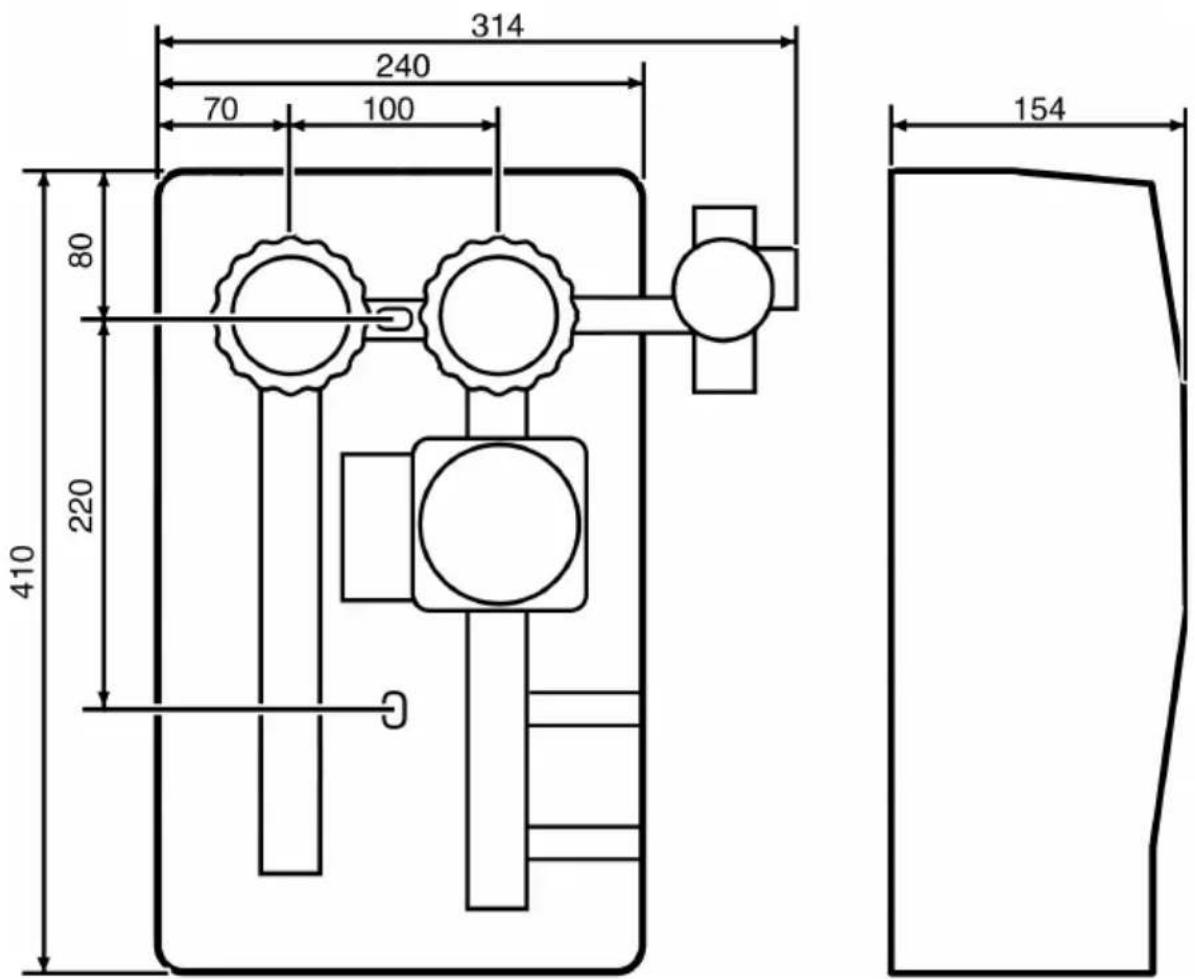
Fig. 2: EKSRDS2A (in mm)
4.3 Function
The product is a pre-assembled, tightness-tested and heat-insulated solar pump assembly with all required safety and functional components.
Both ball valves can be shut off and contain a thermometer and a gravity brake.
4.4 Approvals, conformities, certifications
Refer to the operating instructions of the diaphragm safety valve.
See operating instructions of the manufacturer of the circulation pump for versions with circulation pump.
4.5 Technical data
| Parameter Value | |
| General specifications | |
| System connection G3⁄4 | |
| Weight Max. 5.5 kg | |
| Material of fittings Brass CW617N | |
| Insulation material Polypropylene EPP | |
| System pressure Max. 6 bar | |
| Type of sealing Flat-sealing | |
| Ambient conditions | |
| Ambient temperature operation Max. | 40 °C |
| Temperature of the medium Max. 120 | °C,short-term max. 160 °C |
| Flow meter | |
| Pump connection Pump end with flange and union nutG11⁄2 | |
| Measuring range 2 ... 12 l/min | |
| Combination valve red (flow) | |
| Range 0 ... 120 °C | |
| Combination valve blue (return) | |
| Pump connection Pump end with flange and union nutG11⁄2 | |
| Range 0 ... 120 °C | |
| Safety group assembly | |
| Connection for expansion vessel | G3⁄4 for flex pipe, flat-sealing with union nut |
| Diaphragm safety valve | 6 bar |
| Pressure gauge | ∅ 63 mm, 0 ... 10 bar |
5 Mounting
Only mount the product after having completed all pipe assembly work, all welding work and all soldering work.
- Flush the lines of the system before installing the product.
If you install the product in an existing system, observe the information in chapter "Retrofitting the product".
Observe the operating instructions of the diaphragm safety valve when mounting the product.
5.1 Preparing mounting
→ Verify that the nominal pressure of the product corresponds to the specification value of the system.
→ Verify that the liquid in the system complies with the intended use.
→ Verify that the product has been mounted without a shut-off element.
- Do not install shut-off valves, filters or similar equipment.
→ Verify that the product is mounted in such a way that no external forces can act on the components after it has been installed.
If the expansion vessel is mounted at the same height as the product or higher than the product, the expansion vessel must be protected from thermal loads (for example, heat trap siphon).
5.2 Mounting the product
The product is delivered ready to be installed. You must not dismount any of the parts.
→ Verify that no steam can get into the expansion vessel in the case of stagnation in the system.
→ Verify that all pipe ends are perpendicular and have been deburred.
→ Verify that all sealing surface are clean and free from damage.
→ Verify that the enclosed dowels are suitable for the intended wall.
- Remove the upper insulation.
- Hold the product to the wall and align it with a level
- Draw two marks.
-
Drill a hole ( 10 mm) each.
-
Mount the product using the enclosed dowels and screws.
-
long hanger bolt at the top
-
short hanger bolt at the bottom
-
Fit the product with the bottom insulation and secure it with a washer and a nut.
- Connect the pipes of the solar circuit to the connections of the product (see chapter "Connecting the product").
- Refit the upper insulation.
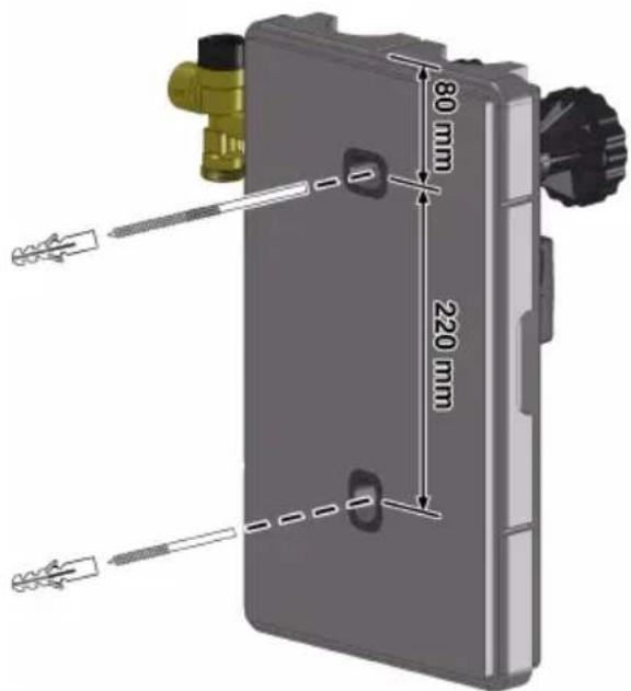
Fig. 3: EKSRDS2A
5.3 Connecting the product
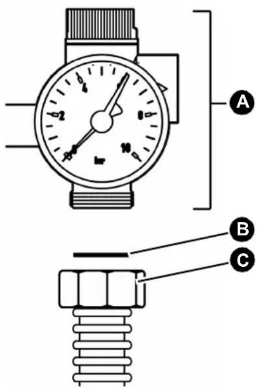
A. Safety group assembly
B. Flat gasket
C. Flex pipe, flat-sealing
Fig. 4: Connection flex pipe G^3/4
- Connect the pipes of the solar circuit to the connections of the product.
- Connect the pipe or flex pipe of the expansion vessel to the safety group assembly.
5.4 Retrofitting the product
WARNING
HOT LIQUID
The liquid in solar systems is under high pressure and can have temperatures of more than 100 °C .
- Verify that the liquid has cooled down before opening the system and mounting the product.
- Verify that the system has been unpressurised and drained before mounting the product.
Failure to follow these instructions can result in death, serious injury or equipment damage.
→ Verify that the nominal pressure of the product corresponds to the specification value of the system.
Verify that the liquid in the system and the application area of the product are compatible.
When the system has cooled down and unpressurised, you can mount the product.
- Drain the system.
- Flush the lines of the system.
- Mount the product as described in chapter "Mounting the product".
5.5 Electrical connection
DANGER
ELECTRIC SHOCK
- Verify that the degree of protection against electric shock (protection class, double insulation) is not reduced by the type of electrical installation.
Failure to follow these instructions will result in death or serious injury.
DANGER
ELECTRIC SHOCK CAUSED BY LIVE PARTS
- Disconnect the mains voltage supply before performing the work and ensure that it cannot be switched on.
- Verify that no hazards can be caused by electrically conductive objects or media.
Failure to follow these instructions will result in death or serious injury.
NOTICE
SUPPLY VOLTAGE FLUCTUATIONS
The pump electronics can be damaged by voltage fluctuations.
- Verify that the pump is not controlled via an external speed controller which changes the supply voltage.
- Verify that the pump is controlled with 230V without phase angle control.
- Switch the pump on and off via the controller.
Failure to follow these instructions can result in equipment damage.
- Connect the circulation pump in accordance with the instructions of the manufacturer.
- Route the connection cable of the circulation pump through the cable duct to the bottom and connect it to the solar controller.
- Observe the operating instructions of the solar controller.
Use a shielded cable 3 x 1.5 mm ^2 and up to ∅ 10 mm to extend the connection cable.
6 Commissioning
Prerequisite for commissioning is a complete installation of all hydraulic and electrical components.
6.1 Commissioning the product
EKSRDS2A is filled via the filling and flushing valves at the flow meter.
- Verify tightness of the components of the system.
- Adapt the test pressure and the test duration to the corresponding installation and the corresponding operating pressure.
- Set to ball valves to 45^ position for filling of the system.
| Thermometer ball valves | ||
 | 0° Normal operation: Ball valve open in direction of flow of solar liquid | |
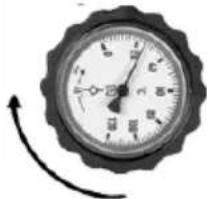 | 90° Maintenance: Ball valve closed | |
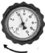 | 45° Commissioning, filling, venting, draining and flushing: Both ends open (gravity brake not active) | |
Filling the system
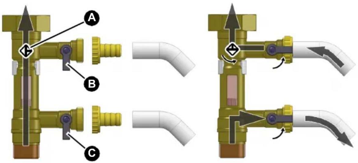
A. Shut-off in return B. Filling and flushing valve
C. Filling and flushing valve
-
Connect the hose connectors and hoses to the filling and flushing valves (B and C).
-
Open the filling and flushing valves and close the shut-off (A).
-
Fill the system with solar liquid via the upper filling valve (B).
-
During filling, verify that all connections are tight.
-
Close the lower shut-off valve (C) as soon as solar liquid escapes there.
-
Apply pressure to the system.
-
Close the upper filling and flushing valve (B).
-
Open the shut-off (A).
-
Vent the system (see chapter "Venting the system").
-
Set the two ball thermometers to 0^ position.
-
Fit the upper part of the insulation onto the product.
-
Make sure the pipe insulation reaches into the corresponding recess of the insulation of the product.
7 Operation
Proper operation is only possible if the thermometer ball valves and the ball valves are open ( 0^ setting).
For safety reasons, liquid must be able to escape via the discharge line of the diaphragm safety valve during heating.
- If the diaphragm safety valve has responded, check the system.
- Remove the cause before recommissioning the system.
7.1 Reading mark at flow meter
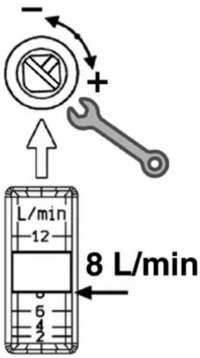
The lower edge of the float is the reading mark at the flow meter.
7.2 Venting the system
WARNING
HOT LIQUID
The liquid in solar systems is under high pressure and can have temperatures of more than 100 °C .
- Verify that the liquid has cooled down (< 50 °C at the red thermometer) before venting the system.
Failure to follow these instructions can result in death, serious injury or equipment damage.
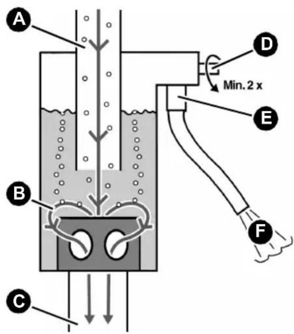
A. Solar liquid with air
B. Direction of flow of solar liquid
C. Vented solar liquid
D. Valve
E. Vent valve with hose
F. Separated air
Fig. 5: Function principle of vent pot
The solar liquid flows into the vent pot from the top (A). The air that is dragged along can be removed from the system by manual venting.
- Put the hose of the vent valve (E) into a collection receptacle.
- Open valve (D).
- The separated air escapes from the vent pot.
- Close the valve (D) as soon as solar liquid escapes.
8 Maintenance
Refer to the operating instructions of the diaphragm safety valve.
8.1 Maintenance intervals
| When Activity | |
| Flow meter can no longer be read | Drain, flush and fill the system. |
9 Troubleshooting
Any malfunctions that cannot be removed by means of the measures described in this chapter may only be repaired by the manufacturer.
Observe the information in the enclosed operating instructions in the case of malfunctions of the circulation pump.
| Problem Possible reason Repair | ||
| Noise in the system Air | in the system Vent the system | stem (see chapter "Venting the system") |
| Pump capacity too high | Set the pump capacity to a lower speed of rotation | |
| Noise in the circulation pump | System pressure is too low | Increase the system pressure or check the gas volume in the expansion vessel |
| Circulation pump does not start | No supply voltage Apply | supply voltage |
| Circulation pump blocked by deposits in the bearings | Observe the information of the pump manufacturer | |
| Circulation pump polluted | Clean the circulation pump | |
| Circulation pump defective | Replace the circulation pump | |
| Problem Possible reason | on Repair | |
| No pressure in the system | Diaphragm safety valve defective | Replace the product |
| Expansion vessel not tight | Replace the expansion vessel | |
| Leak in the system Contact your specialised company | ||
| When the system is drained, no liquid escapes via the filling and flushing valves | Ball valves and/or are shut-off closed | Set the ball valves to 45° position and open shut-off |
| Other malfunctions - Send the product to the manufacturer | ||
9.1 Replacing the circulation pump
DANGER
ELECTRIC SHOCK CAUSED BY LIVE PARTS
- Disconnect the mains voltage supply before performing the work and ensure that it cannot be switched on.
Failure to follow these instructions will result in death or serious injury.
- Disconnect the mains voltage.
- Close the shut-off at the flow meter and set the blue ball valve to 90^ position.
- Replace the circulation pump.
- Use new seals.
- Open the shut-off at the flow meter and set the blue ball valve to 0^ position.
- Fill and vent the system.
- Connect the circulation pump to supply voltage.
10 Decommissioning, disposal
Dispose of the product in compliance with all applicable directives, standards and safety regulations.
Electronic components must not be disposed of together with the normal household waste.
- Disconnect the product from mains.
- Dismount the product (see chapter "Mounting", reverse sequence of steps).
- Dispose of the product.
11 Returning the device
Get in touch with us before returning your product (customercare@daikin.de).
12 Warranty
The manufacturer's warranty for this product is 24 months after the date of purchase. This warranty shall be good in all countries in which this product is sold by the manufacturer or its authorised dealers.
natural_image
3D mechanical assembly diagram showing internal components and a separate gray plastic housing (no text or symbols)natural_image
3D mechanical assembly diagram showing internal components of a device housing (no text or symbols)MANUTENTION INAPPROPRIÉE
FLUCTUATIONS DE LA TENSION D'ALIMENTATION
natural_image
3D mechanical assembly diagram showing internal components and housing (no text or symbols)Figura 2: EKSRDS2A (in mm)
4.3 Funzionamento
natural_image
3D mechanical assembly diagram showing internal components and housing (no text or symbols)natural_image
3D mechanical assembly diagram showing internal components and housing (no text or symbols)A. Sistema de segurança
B. Junta plana
C. Tubo corrugado de junta plana