
ASP 100 - Tiller accessory STIHL - Free user manual and instructions
Find the device manual for free ASP 100 STIHL in PDF.

| Brand | Stihl |
| Model | ASP 100 |
| Product type | Tiller attachment (snow blade) |
| Working width in centered position | 1000 mm |
| Working width in angled position | 872 mm |
| Blade height | 500 mm |
| Weight | 46 kg |
| Total length | 637 mm |
| Main functions | Snow clearing, pivoting on 3 positions, pedal lift |
| Tractor compatibility | RT 4082, RT 4097 S/SX, RT 4112 S/SZ, RT 5097/C/Z, RT 5112 Z, RT 6112 C/ZL, RT 6127 ZL |
| Safety features | Tripping springs, anti-scalp wheels, skid shoe, locking lever |
| Maintenance | Greasing lubrication points, turning/replacing skid shoe, adjusting springs |
| Common spare parts | Skid shoe (ref. 6907 731 8305), Anti-scalp wheel (ref. 6170 704 9700) |
| Recommended accessories | Snow chains ASK 016/018/020 |
| Main material | Steel (estimated) |
| Power supply | None (mechanical attachment) |
| Cleaning | With running water, no pressure washer |
| Storage | Dry and closed room, blade in stable position |
| Repairability index | High (spare parts available, adjustments possible) |
| Warranty | STIHL manufacturer warranty (not specified) |
Frequently Asked Questions - ASP 100 STIHL
User questions about ASP 100 STIHL
0 question about this device. Answer the ones you know or ask your own.
Ask a new question about this device
Download the instructions for your Tiller accessory in PDF format for free! Find your manual ASP 100 - STIHL and take your electronic device back in hand. On this page are published all the documents necessary for the use of your device. ASP 100 by STIHL.
USER MANUAL ASP 100 STIHL
natural_image
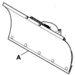
Technical line drawing of a snow plow assembly (no text or symbols)ASP 100.1 ASP 125.1
2
natural_image
Technical line drawing of a mechanical component with mounting holes and a curved base (no text or symbols)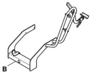
natural_image
Technical line drawing of a mechanical bracket or clamp assembly (no text or symbols)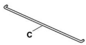
natural_image
Simple line drawing of a diagonal line with label 'C' at one end (no other text or symbols)ASP 100
natural_image
Technical line drawing of a curved metal frame with mounting holes and a labeled component 'A' (no text or symbols beyond label)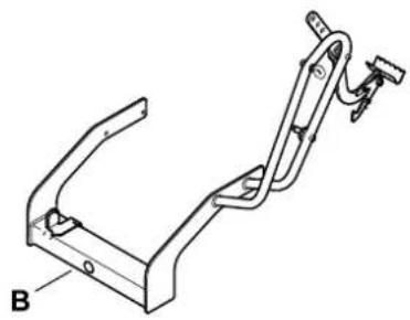
natural_image
Technical line drawing of a mechanical bracket or support structure (no text or symbols)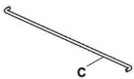
natural_image
Simple line drawing of a diagonal pipe or rod with a labeled point 'C' (no text or symbols beyond the label)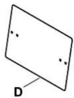
ASP 125
natural_image
Line drawing of a long, straight tool or rod with a labeled end point 'H' (no other text or symbols)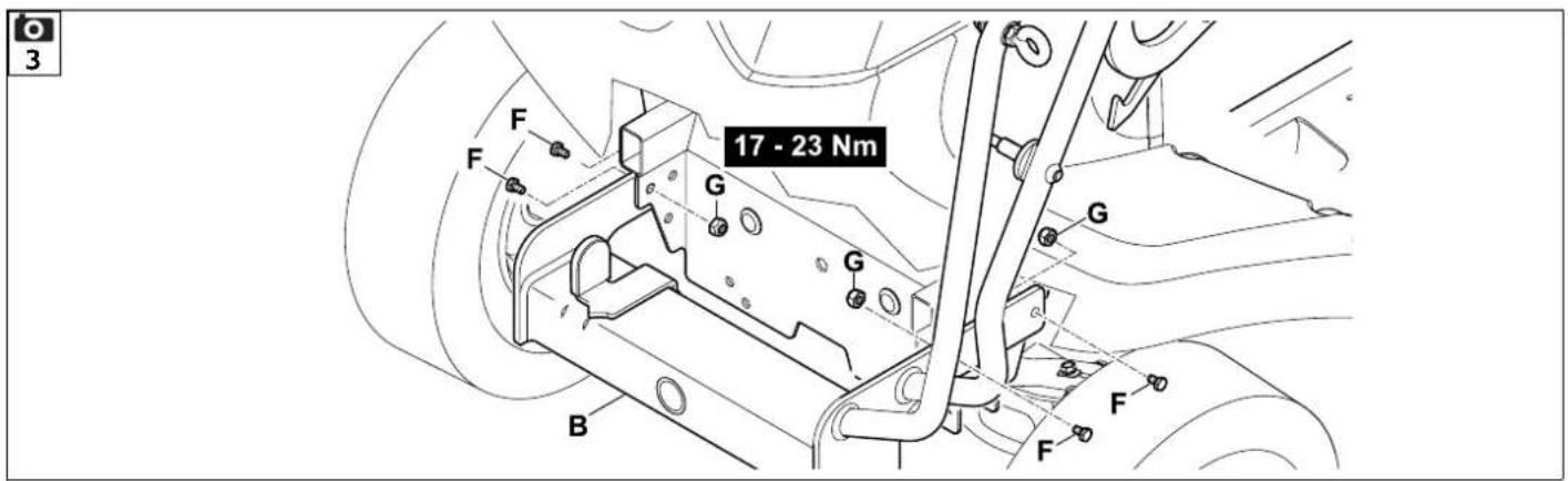
6
7
8
natural_image
Mechanical assembly diagram showing a motor with wheels and a camera icon (no text or labels)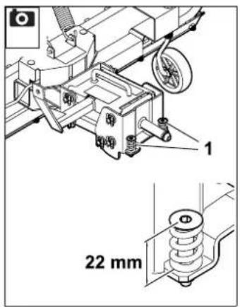
2
Thank you for choosing STIHL. We develop and manufacture our quality products to meet our customers' requirements. The products are designed for reliability even under extreme conditions.
STIHL also stands for premium service quality. Our specialist dealers guarantee competent advice and instruction as well as comprehensive service support.
We thank you for your confidence in us and hope you will enjoy working with your STIHL product.

Dr. Nikolas Stihl
IMPORTANT: READ BEFORE USE AND KEEP IN A SAFE PLACE.
1. Table of contents
Notes on the instruction manual 26
General 26
Instructions for reading the instruction manual 26
Machine overview 26
For your safety 27
General 27
Before operation 27
Working with your appliance 27
Storage for prolonged periods without operation 28
Disposal 28
Description of symbols 28
Standard equipment 28
Frame installation 29
General information on installing the mounting frame 29
Reading off the model designation on the ride-on mower and determining the installation variant 29
Installing the mounting frame – variant 1 29
Installing the mounting frame – variant 2 29
Assembling the snow plough 29
Assembling the snow plough 29
Installing and removing the snow plough 30
Installing the cover 30
Installing the snow plough 30
Installing the lift rod 30
Installing the swivel rod 31
Removing the snow plough 31
Removing the cover 31
Controls 32
Lift pedal 32
Swivel rod 32
Notes on working with the machine
Clearing large areas 33
Snowploughing paths 33
Preparing the ride-on mower for winter use
Precautions for winter operation 33
Operating the machine
Preparing the ride-on mower for operation 33
Placing the snow plough in the transport position 34
Lowering the snow plough into the working position
Swivelling the snow plough 34
Snowploughing 34
Parking the ride-on mower with snow plough
Maintenance
General 35
Maintenance schedule 35
Lubrication 36
Reversing or replacing a slide bar 36
Adjusting the thrust spring 36
Adjusting the snow plough
Adjusting the gauge wheels 37
Adjusting the coil springs 37
Adjusting the lift rod 37
Transport
Lifting the snow plough 38
Transporting the ride-on mower with installed snow plough 38
Standard spare parts
Accessories 38
Snow chains 38
Environmental protection
Declaration on the installation of an incomplete machine 38
Technical specifications 39
Troubleshooting 39
2. Notes on the instruction manual
2.1 General
This instruction manual constitutes original manufacturer's instructions in the sense of EC Directive 2006/42/EC.
STIHL is continually striving to further develop its range of products; we therefore reserve the right to make alterations to the form, technical specifications and equipment level of our standard equipment.
For this reason, the information and illustrations in this manual are subject to alterations.
This instruction manual may describe models that are not available in all countries.
This instruction manual is protected by copyright. All rights reserved, especially the right of reproduction, translation and processing using electronic systems.
2.2 Instructions for reading the instruction manual
Illustrations and texts describe specific operating steps.
All symbols which are affixed to the machine are explained in this instruction manual.
Viewing direction:
Viewing direction when "left" and "right" are used in the instruction manual: the user is standing behind the machine and is looking forwards in the direction of travel.
Section reference:
References to relevant sections and subsections for further descriptions are made using arrows. The following example shows a reference to a section: ( 3.)
Designation of text passages:
The instructions described can be identified as in the following examples.
Operating steps which require intervention on the part of the user:
- Release bolt (1) using a screwdriver, operate lever (2)...
General lists:
– Use of the product for sporting or competitive events
Texts with added significance:
Text passages with added significance are identified using the symbols described below in order to especially emphasise them in the instruction manual:

Danger
Risk of accident and severe injury to persons. A certain type of behaviour is necessary or must be avoided.

Warning
Risk of injury to persons. A certain type of behaviour prevents possible or probable injuries.

Caution
Minor injuries or material damage can be prevented by a certain type of behaviour.

Note
Information for better use of the machine and in order to avoid possible operating errors.
Texts relating to illustrations:
Illustrations relating to use of the machine can be found in the front of this instruction manual.
The camera symbol serves to link the figures on the illustration pages with the corresponding text passages in the instruction manual.

3. Machine overview
1 Snow plough assembly
2 Locking lever
3 Lift pedal
4 Swivel rod
5 Lift rod
6 Locking lever
7 Handle
8 Coil springs
9 Slide bar
10 Gauge wheels
4. For your safety
4.1 General

These safety regulations must be observed when working with the ride-on mower and attached accessories.

Read the entire instruction manual before using the machine for the first time. Keep the instruction manual in a safe
place for future reference.
Please also observe the instruction manual of the ride-on mower – particularly the safety instructions in the section “For your safety”.
The safety instructions contained in this instruction manual supplement the safety instructions in the instruction manual of the ride-on mower.
Caution – risk of accident!
The snow plough may only be used to clear snow; its use for other purposes is not permitted.

Risk of death from suffocation!
Packaging material is not a toy - danger of suffocation! Keep packaging material away from children.
Always keep warning and information stickers clean and readable. Damaged or missing stickers must be replaced by new, original plates from your STIHL specialist dealer. If a component is replaced with a new component, ensure that the new component is provided with the same stickers.
4.2 Before operation
Make sure that only persons who are familiar with the instruction manual are permitted to use the machine.
Ensure that you are familiar with all of the controls of the accessory before use.
Before using the ride-on mower on snow or ice-covered roads, snow chains should be fitted on the wheels.
Snow chains are available as accessories (see the section "Recommended accessories").
Ensure that sufficient lighting is available throughout the entire snow ploughing procedure.
Familiarise yourself with the contour of the area to be cleared beforehand. Avoid depressions (holes, recesses, ripples, etc.) at all times.
Check the area to be cleared thoroughly and mark or remove all protruding obstacles such as overhangs, flagstones, edges, large stones, etc. Obstacles may be hidden by snow.
Never use the machine with damaged safety devices or with safety devices removed.
Make sure that the locking lever is fully engaged before each use if there is a snow plough installed. ( 9.2)
Risk of injury!
Only operate the machine when properly assembled.
Before using the machine, always carry out a visual check to ensure that it is in good operating condition.
"Good operating condition" means that the machine is fully assembled, in particular:
- both gauge wheels are mounted,
– the protective cover on the snow plough is installed and functional,
– the slide bar is installed and functional,
– all cotter pins are properly installed,
– all bolted connections are present and securely tightened.
4.3 Working with your appliance
Caution – risk of injury!
After the mounting frame and the snow plough have been attached, the handling characteristics of the ride-on mower change due to the increased length, additional weight on the front axle (tyre pressure) and modified centre of gravity.
Adjust the driving speed accordingly.
Caution – risk of injury!
There may be hidden obstacles under the snow blanket to be cleared, therefore the steering wheel must always be firmly held with both hands when clearing snow.
Avoid abrupt steering and braking.
Always adapt the driving speed to the external conditions. Because of the reduced traction of the wheels on snow or ice-covered roads, always select a slow driving speed (walking speed).
The reduced traction of the wheels on snow or ice-covered roads has the following effects on the driving characteristics:
- Longer braking distances.
- Strong understeer. When steering, the ride-on mower may lose its course and continue straight when the front wheels are turned or follow a wider turning radius.
- When driving on inclines, the ride-on mower may skid more easily.
When the snow plough is installed, the increased weight makes steering more difficult. Adjust the driving speed accordingly.
Caution – risk of injury!
During winter operation, particularly at low temperatures and on snow or ice-covered roads, driving on inclines should be avoided because the ride-on mower may skid due to the reduced traction of the wheels.
For this reason, only slopes with a slope inclination that is significantly smaller than 10^ can be driven on safely in winter, particularly when clearing snow.
4.4 Storage for prolonged periods without operation
Ensure that the machine is protected from unauthorised use (e.g. by children).
Thoroughly clean the machine before storage (e.g. winter break).
Do not use high-pressure cleaners to clean the snow plough. Only clean the snow plough under running water (e.g. a garden hose).
Store the machine in good operational condition.
Perform all the necessary maintenance operations (lubrication, etc.) before storing the machine. ( 14.2)
Store the machine in a dry and locked place.
Store the snow plough in a safe position in a safe place. The snow plough is in a safe position when it is resting on the slide bar
and the two gauge wheels. Additionally secure the snow plough against falling over and moving independently.
4.5 Disposal
Waste products can be harmful to people, animals and the environment. They must consequently be disposed of properly.
Consult your recycling centre or your specialist dealer for information on the proper disposal of waste products. STIHL recommends STIHL specialist dealers.
5. Description of symbols

Caution!
Read the instruction manual before initial use.


Caution - danger of crushing!
Never put hands or feet on or underneath moving parts.
Risk of injury!
Keep other persons out of the danger area.
Danger of burns!
Do not touch hot surfaces. Engine components, especially mufflers and surrounding parts, can become extremely hot.

ASP 125:
Wear work gloves when car-rying out any work on the snow plough, mounting frame or mounting with handle!
6. Standard equipment

Item Designation Qty.
ASP 100:
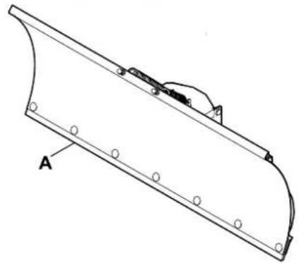
A Snow plough assembly 1
B Mounting frame 1
C Lift rod 1
ASP 125:
A Snow plough assembly 1
B Mounting frame 1
C Lift rod 1
D Cover 1
ASP 100, ASP 125:
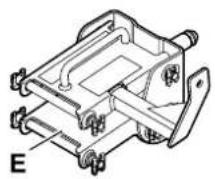
E Snow plough mounting 1
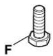
F Bolt 4
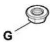
G Lock nut 4
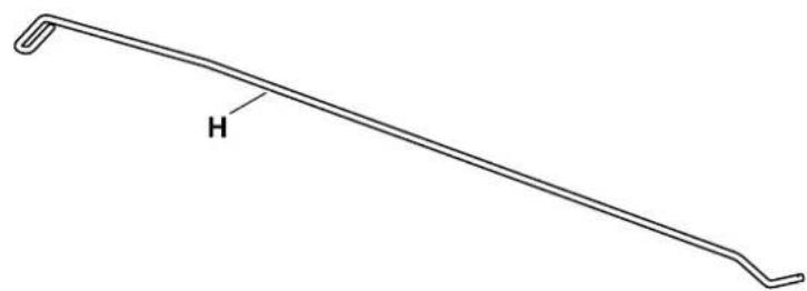
H Swivel rod 1 – Instruction manual 1
7. Frame installation
7.1 General information on installing the mounting frame
The mounting frame is installed in one of two ways, depending on the model designation of the ride-on mower. To determine the correct installation variant, the model designation must first be read off on the ride-on mower. The correct installation variant can then be defined using this model designation. ( 7.2)
7.2 Reading off the model designation on the ride-on mower and determining the installation variant
- Fold up the seat and read off the model designation (type) on the rating plate.
Installation variant 1: ( 7.3)
RT 4082
Installation variant 2: (→ 7.4)
RT 4097 S, RT 4097 SX, RT 4112 S,
RT 4112 SZ /
RT 5097, RT 5097 C, RT 5097 Z,
RT 5112 Z /
RT 6112 C, RT 6127 ZL, RT 6112 ZL
7.3 Installing the mounting frame – variant 1

These instructions for installing the mounting frame of the snow plough on the ride-on mower are valid for the model RT 4082:
- Push on mounting frame (B) and push bolts (F) through the bores from the outside.
- Screw on lock nuts (G) (do not tighten). Repeat this procedure on the other side.
- Counterhold lock nuts (G) using a spanner and tighten bolts (F) to 17-23 Nm. Repeat this procedure on all four bolts.
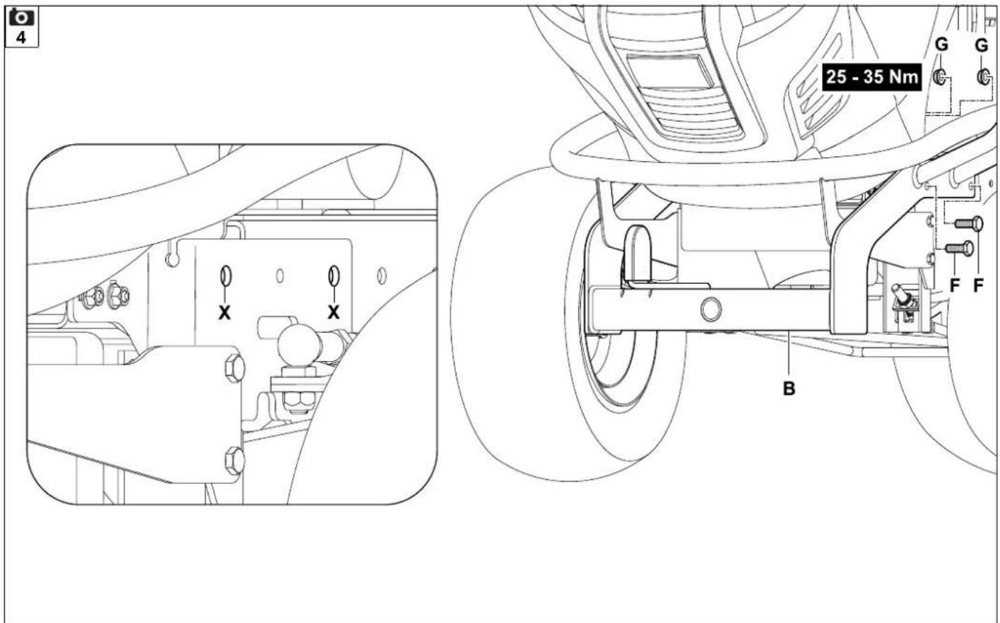
7.4 Installing the mounting frame – variant 2

These instructions for installing the mounting frame of the snow plough on the ride-on mower are valid for the following models:
RT 4097 S, RT 4097 SX, RT 4112 S, RT 4112 SZ /
RT 5097, RT 5097 C, RT 5097 Z, RT 5112 Z /
RT 6112 C, RT 6112 ZL, RT 6127 ZL:
- Use bores (X) in the frame for the bolt fastening.
- Push on mounting frame (B) and push bolts (F) all the way through the bores from the outside. Screw on lock nuts (G) on the inside of the frame (do not tighten).
- Repeat this procedure on the other side.
- Counterhold lock nuts (G) using a spanner and tighten bolts (F) to 25-35 Nm. Repeat this procedure on all four bolts.
8. Assembling the snow plough
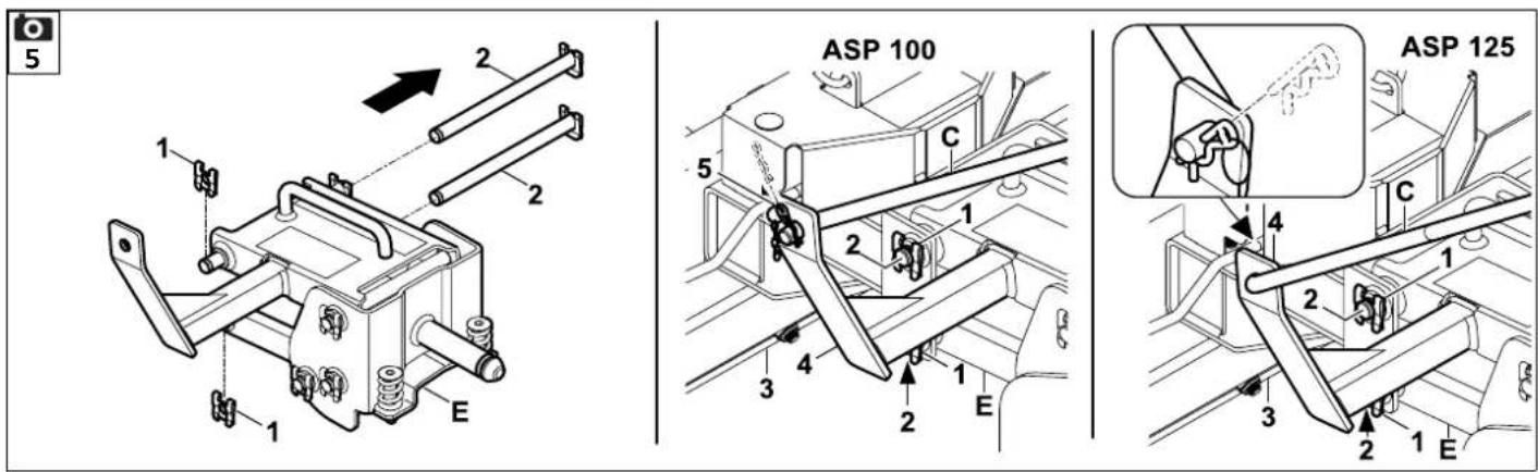
8.1 Assembling the snow plough

- Remove lock washers (1) from one side of studs (2). Pull studs (2) out of snow plough mounting (E) and remove.
- Place snow plough mounting (E) on snow plough (3). Guide studs (2) as far as they will go through the bores in snow plough (3) and snow plough mounting (E). Slide lock washers (1) as far as they will go onto both studs (2).
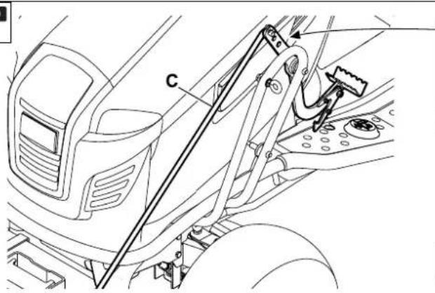
- ASP 100: Insert lift rod (C) into the bore in bracket (4) from the inside. Insert cotter pin (5) into the bore in lift rod (C).
- ASP 125: Insert lift rod (C) into the bore in bracket (4) from the outside. Insert cotter pin (5) into the bore in lift rod (C).
9. Installing and removing the snow plough
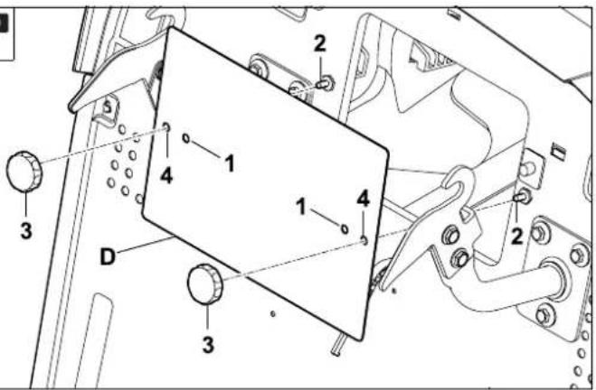
9.1 Installing the cover


Note!
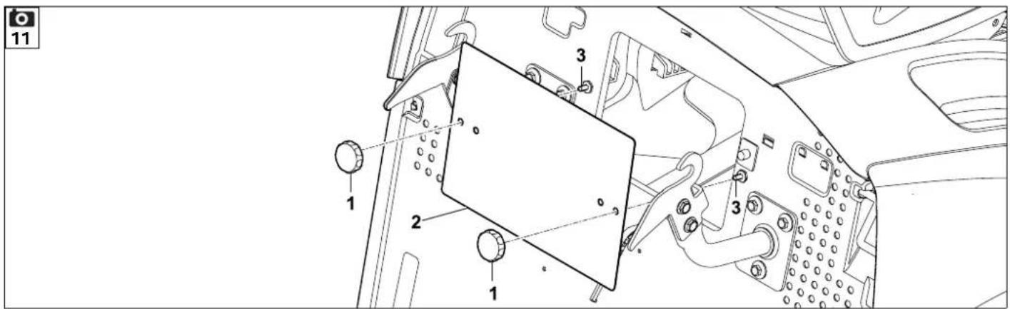
To prevent damage to the discharge chute when the mowing deck is not installed, it must be removed on the models RT 4082, RT 5097/ C/ Z, RT 5112 Z and RT 6112 C/ ZL, RT 6127 ZL. When the discharge chute is not installed, the cover must be installed as a safety device.
- RT 4082, RT 5097/ C/ Z, RT 5112 Z and RT 6112 C/ ZL, RT 6127 ZL: Remove the discharge chute. (See instruction manual of the ride-on mower)
- RT 5097/ C/ Z, RT 5112 Z: Fit cover (D) onto screws (2) using the respective inner bores (1). Fasten cover (D) by turning nuts (3).
- RT 6112 C/ ZL, RT 6127 ZL: Fit cover (D) onto screws (2) using the respective outer bores (4). Fasten cover (D) by turning nuts (3).
9.2 Installing the snow plough


Risk of injury!
Do not lift snow plough (A) when installing it. Take account of the weight of the snow plough assembly. ( 21.)
For safety reasons, the snow plough should only be lifted with the help of a second person. ( 16.1)
Keep others away from the direct vicinity when installing the snow plough.
ASP 125:
Wear work gloves when installing the snow plough. Danger of burns due to hot parts (exhaust, etc.) on the ride-on mower!
- Stop the engine. (See instruction manual for the ride-on mower)
- Engage the parking brake. (See instruction manual for the ride-on mower)
- Remove the mowing deck. (Follow the instructions in the instruction manual for the ride-on mower precisely)
• Install the cover. (⇔ 9.1)

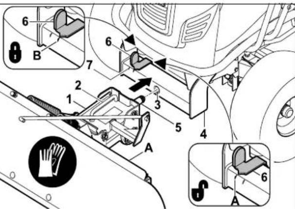
Hold handle (2) with one hand when installing the snow plough. With the other hand, press locking lever (6).
Danger of burns!
Avoid contact with the hot exhaust when pressing the locking lever. The model RT 4082 is an exception to this. The exhaust is not near the locking lever on these models.
Danger of pinching!
Do not hold the snow plough at moving parts during installation.
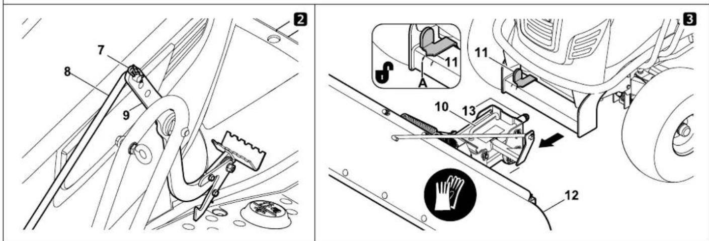
- Tilt snow plough (A) slightly so that it is balancing on the two gauge wheels. Lift snow plough mounting (1) at handle (2). Push the snow plough towards mounting bore (3) in mounting frame (4). Insert stud (5) into mounting bore (3).
- Push locking lever (6) outwards until the arrow on the locking lever lines up with outer marking (A).
- Push snow plough (A) as far as it will go onto mounting frame (4). Release locking lever (6) again, making sure it engages fully. When the locking lever is engaged, the arrow lines up with inner marking (B).
• Install the lift rod. ( 9.3)
• Install the swivel rod. (⇒ 9.4)
9.3 Installing the lift rod

• Install the snow plough. (⇒ 9.2)
- Read the section "Adjusting the lift rod" before installing the lift rod. ( 15.3)
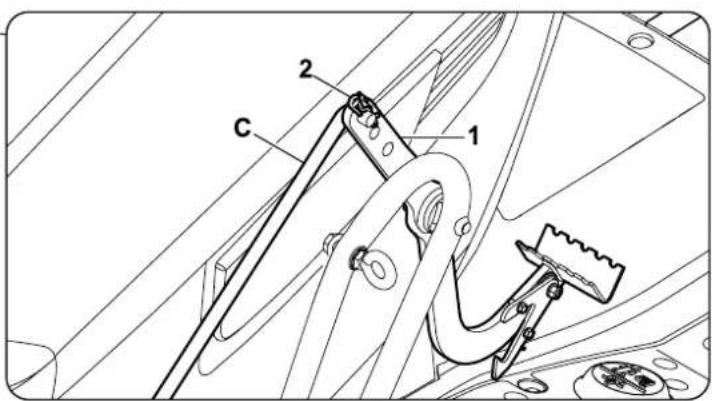
- Insert lift rod (C) into one of the three bores in lift arm (1). Insert cotter pin (2) into the bore in the lift rod.
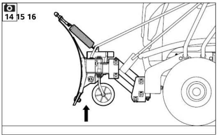
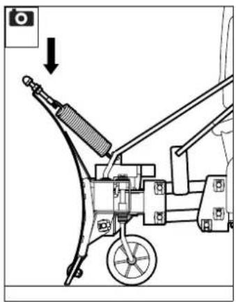
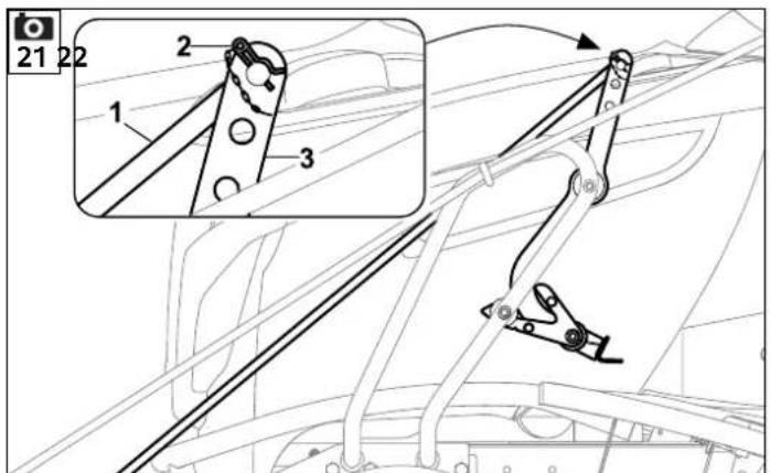
9.4 Installing the swivel rod


Note!
Cut the cable tie at the bracket using side cutters and remove during initial installation – caution: danger of cuts!
• Install the snow plough. (⇔ 9.2)
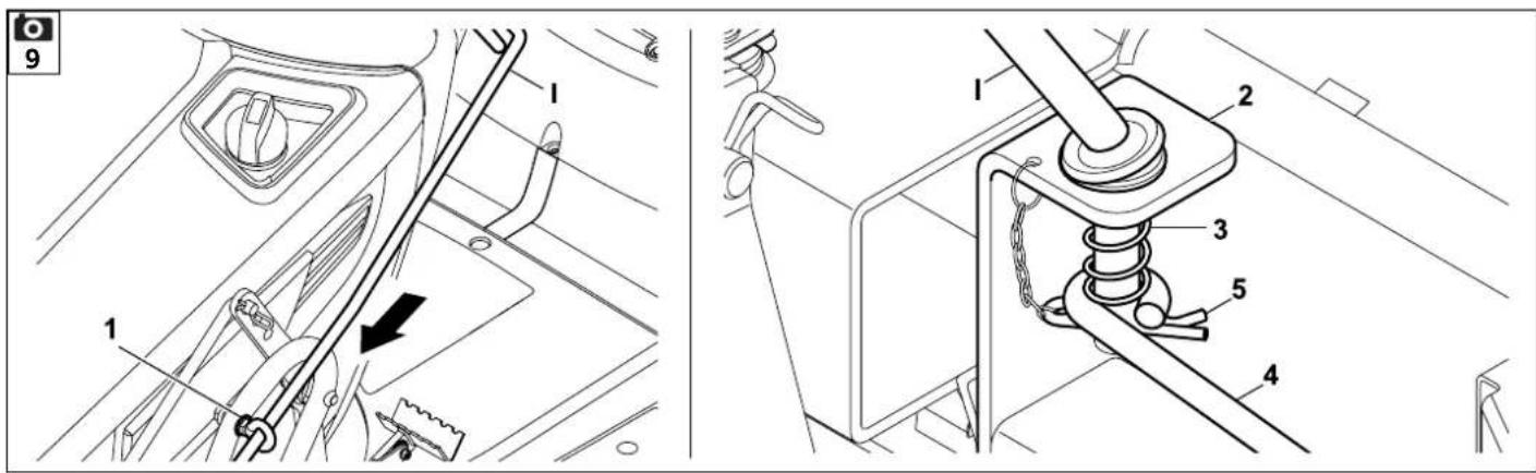
- Push swivel rod (I) into ring nut (1) from above.
- Push swivel rod (I) into bracket (2) and spring (3) on the snow plough. Attach release rod (4) to swivel rod (I). Insert cotter pin (5) through the bore in swivel rod (I).
9.5 Removing the snow plough


Risk of injury!
Do not lift the snow plough when removing it. Take account of the weight of the snow plough assembly. ( 21.)
For safety reasons, the snow plough should only be lifted with the help of a second person. ( 16.1)
Keep others away from the direct vicinity when removing the snow plough.
ASP 125:
Wear work gloves when removing the snow plough. Danger of burns due to hot parts (exhaust, etc.) on the ride-on mower!
- Stop the engine. (See instruction manual for the ride-on mower)
- Engage the parking brake. (See instruction manual for the ride-on mower)
- Swivel the snow plough to the central position. ( 13.4)
- Lower the snow plough into the working position. ( 13.3)
Step 1
Removing the swivel rod:
- Detach the swivel rod at the snow plough:
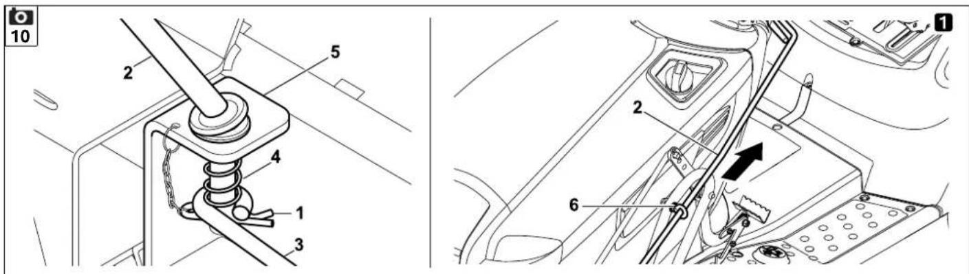
Pull out cotter pin (1) at swivel rod (2), remove release rod (3) from the swivel rod and place to one side. Pull swivel rod (2) out from spring (4) and bracket (5). - Remove the swivel rod at the frame: Pull swivel rod (2) out from ring nut (6) upwards.
Step 2
Detaching the lift rod:
- Pull out cotter pin (7) at lift rod (8). Detach lift rod (8) from lift arm (9). Turn lift rod (8) forwards and lean against the snow plough.
Step 3
Removing the snow plough:

Hold the snow plough at handle (10) with one hand when removing it. With the other hand, press locking lever (11).
Risk of injury!
Avoid contact with the hot exhaust and the surrounding parts when pressing the locking lever. The model RT 4082 is an exception to this. The exhaust is not near the locking lever on these models.
Danger of pinching!
Do not hold the snow plough at moving parts during removal.
- Pull locking lever (11) outwards as far as marking (A) and hold. Pull snow plough (12) forwards until stud (13) is freely accessible.
- Release locking lever (11) again.

Avoid damage to the machine! When installing the mowing deck, always remove the cover and install the discharge chute. The mowing deck must only be used with the discharge chute installed.
9.6 Removing the cover


Note
On the models RT 5097/ C/ Z, RT 5112 Z, RT 6112 C/ ZL, RT 6127 ZL, the discharge chute must be installed after the cover is removed.
• Unscrew and remove nuts (1).
- Detach and remove cover (2) from bolts (3).
- Install the discharge chute. (See instruction manual for the ride-on mower)
10. Controls
10.1 Lift pedal


Danger of crushing!
Only operate the lift pedal from the driver's seat of the ride-on mower. Keep others away from the direct vicinity when lowering the snow plough.
Only press the lift pedal when the ride-on mower is at a complete standstill.
Always counterhold the lift pedal securely with the foot when pressing it (lifting or lowering) and guide it until it reaches the working position or transport position. Do not allow the snow plough to fall abruptly to the ground when lowering it.

Note!
The following maximum forces can be required to operate the lift rod depending on the setting:
ASP 100: 255 N (26 kg)
ASP 125: 294 N (30 kg)
The snow plough has two positions - the transport position and the working position.
When the snow plough is in the transport position, it is raised and is not in contact with the ground.
When the snow plough is in the working position, its entire weight is on the ground.
The position of the snow plough can be changed conveniently from the driver's seat using the lift pedal.
Raising the snow plough:
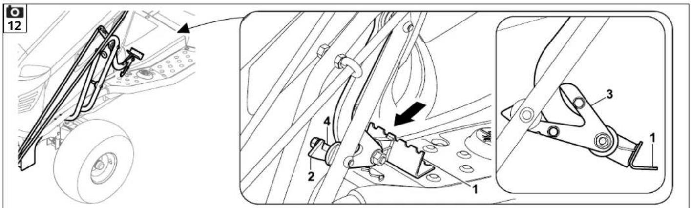
- Press lift pedal (1) down as far as it will go with the foot until locating lug (2) of locking lever (3) engages at stud (4).
Lowering the snow plough:
- Press lift pedal (1) down slightly with the foot, pressing locking lever (3) forwards as far as it will go with the tip of the foot and holding. Slowly guide lift pedal (1) upwards with the foot until the snow plough is in full contact with the ground. Remove foot from lift pedal (1).
10.2 Swivel rod


Danger of crushing!
Only operate the swivel arm release from the driver's seat of the ride-on mower.
Keep others away from the direct vicinity when swivelling the snow plough.
After the swivel arm release has been actuated, the snow plough can be swivelled into 3 positions with the aid of the swivel rod.
Never actuate the swivel arm release while clearing snow. Unload the snow plough before each actuation by raising it into the transport position.
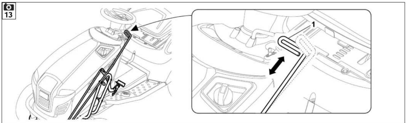
Turning swivel rod (1) releases the snow plough. The snow plough can then be swivelled.
After swivel rod (1) is released, the snow
plough engages in one of the 3 positions. The snow plough is locked in place after it engages.
Releasing and swivelling the snow plough:
- Turn the swivel rod (1) inwards (clockwise) at the handle and hold. The locking mechanism is released and the snow plough can be swivelled by pushing or pulling the swivel rod.
Locking the snow plough in place:
- Release swivel rod (1). When the snow plough is in one of the 3 notched positions, the locking mechanism engages automatically. The snow plough is locked in place and cannot be swivelled until it is released again.
11. Notes on working with the machine

Warning! Risk of injury!
Carefully read and observe the section "For your safety" before operating the machine. ( 4.) Observe all information regarding safe operation of the machine. Use of the ride-on mower is not permitted on public roads.
When clearing snow, the height and characteristics of the snow (temperature dependent) must be taken into consideration.
These two factors have a significant influence on the clearing performance of the machine.
11.1 Clearing large areas
Examples:
Wide driveway, car park, courtyard, etc.
Tips:
- Bring the snow plough into the straight position (90° to driving direction).
- Depending on the height and characteristics of the snow in the centre of the area to plough, clear a path (track) with the ride-on mower or snow shovel first.
- Gradually remove an appropriate amount of snow from the left and right snow-covered area; adjust the width based on the height and characteristics of the snow and traction of the wheels. Repeat this procedure until the entire surface is cleared.
11.2 Snowploughing paths
Examples:
Narrow path in a park, etc.
Tip:
- Swivel the snow plough to the left or right and allow it to engage. Clear the path by following its course carefully.
12. Preparing the ride-on mower for winter use
12.1 Precautions for winter operation

Note
Because of the cold and damp conditions, various precautions need to be taken for use in winter. These precautions ensure that the mower is ready for use and prevent damage to the machine.
Recommendations for safe winter operation of the ride-on mower:
- At low temperatures, use HD 15 W40 grade engine oil.
- After using the ride-on mower, store it in a closed, well-ventilated room (garage). If possible, do not leave the machine outdoors.

Risk of injury!
Petrol represents an explosive hazard! Never park the ride-on mower near a heat source.
13. Operating the machine

Risk of injury!
Carefully read and observe the section "For your safety" before operating the machine. ( 4.) Observe all information regarding safe operation of the machine. In addition, observe all safety instructions contained in the instruction manual of the ride-on mower. The additional weight, modified weight distribution (changed centre of gravity) and increased overall length when the snow plough is attached to the ride-on mower change the handling characteristics of the mower.
- Before use, check the settings on the snow plough and adjust them if necessary. ( 15.)
- Familiarise yourself with all of the controls of the snow plough before using it. ( 10.)
- Familiarise yourself with all of the controls of the ride-on mower before using it.
13.1 Preparing the ride-on mower for operation
- RT 4097 S/ SX, RT 4112 S/ SZ: Remove the mowing deck. (See instruction manual of the ride-on mower)
- RT 4082, RT 5097/ C/ Z, RT 5112 Z, RT 6112 C/ ZL, RT 6127 ZL: Remove the mowing deck, grass catcher box and discharge chute. (See instruction manual of the ride-on mower)
- RT 5097/ C/ Z, RT 5112 Z, RT 6112 C/ ZL, RT 6127 ZL: Install the cover ( 9.1).
- Prepare the ride-on mower for winter use. (⇔ 12.)
13.2 Placing the snow plough in the transport position

- Bring the ride-on mower to a complete standstill. (See instruction manual of the ride-on mower)
- Raise the snow plough. (⇒ 10.1)
13.3 Lowering the snow plough into the working position

- Bring the ride-on mower to a complete standstill.
(See instruction manual of the ride-on mower)
• Lower the snow plough. (⇒ 10.1)
13.4 Swivelling the snow plough
- Bring the ride-on mower to a complete standstill. (See instruction manual of the ride-on mower)
- Raise the snow plough into the transport position.
-
Turn the swivel rod and hold. (⇒ 10.2)
-
Swivel the snow plough into the desired position by pulling or pushing the swivel rod. ( 10.2)
- Release the swivel rod and ensure that the locking mechanism engages in the snow plough.
13.5 Snowploughing
Risk of injury!
⚠️ Clear snow at walking speed only, never at maximum driving speed. Prior to ploughing, check the area to be cleared thoroughly and mark or remove all protruding obstacles (overhangs, pavement, flagstones, etc.). Approach large accumulations of snow (e.g. already ploughed snow) at low speed only.
Note
Before ploughing, read and observe the section "Notes on working with the machine". ( 11.)
Starting (hydrostatic gearbox):
Note
Please see the ride-on mower instruction manual to determine whether the mower is equipped with a hydrostatic or manual gearbox.
- Start the engine. (See instruction manual of the ride-on mower)
- If necessary, turn the light on. (See instruction manual of the ride-on mower)
-
Raise the snow plough into the transport position. ( 13.2)
-
Drive the ride-on mower onto the area to be cleared. (See instruction manual of the ride-on mower)
- Set the throttle lever to the MAX position. The throttle lever must always be in the MAX position while clearing snow. (See instruction manual of the ride-on mower)
- Swivel the snow plough into the desired position. (⇒ 10.2)
- Lower the snow plough into the working position. ( 13.3)
- Press the drive pedal slowly and carefully. The ride-on mower starts moving slowly. If necessary, increase the driving speed. (See instruction manual of the ride-on mower)
Braking (hydrostatic gearbox):
- Release pressure on the drive pedal until the ride-on mower comes to a standstill.
(See instruction manual of the ride-on mower) - Operate the brake as required. (See instruction manual of the ride-on mower)
- Place the snow plough in the transport position if necessary. (⇒ 13.2)
Starting (manual gearbox):

Note
Please see the ride-on mower instruction manual to determine whether the mower is equipped with a hydrostatic or manual gearbox.
- Start the engine. (See instruction manual of the ride-on mower)
- If necessary, turn the light on. (See instruction manual of the ride-on mower)
- Raise the snow plough into the transport position. (⇒ 13.2)
- Drive the ride-on mower onto the area to be cleared. (See instruction manual of the ride-on mower)
- Set the throttle lever to the MAX position. The throttle lever must always be in the MAX position while clearing snow. (See instruction manual of the ride-on mower)
- Swivel the snow plough into the desired position. (⇒ 10.2)
- Lower the snow plough into the working position. (⇔ 13.3)
For models with a manual gearbox, snowploughing may only be performed in first gear for safety reasons. - With the clutch/brake pedal pressed down, select first gear.
(See instruction manual of the ride-on mower) - Slowly release the clutch/brake pedal. (See instruction manual of the ride-on mower)
- Press the clutch/brake pedal down evenly and hold. The ride-on mower stops. (See instruction manual of the ride-on mower)

Risk of injury!
Braking (manual gearbox):
- Place the snow plough in the transport position if necessary. ( 13.2)
13.6 Parking the ride-on mower with snow plough

Risk of injury!
For safety reasons, always lower the snow plough completely when storing the ride-on mower.
- Park the ride-on mower safely. (See instruction manual of the ride-on mower)
- Engage the parking brake. (See instruction manual of the ride-on mower)
- Lower the snow plough completely (working position) ( 13.3)
14. Maintenance

Risk of injury!
Read and observe the section "For your safety" before all maintenance and repair work. ( 4.) Also carefully read and observe the section "For your safety" in the instruction manual of the ride-on mower. Remove the ignition key and keep in a safe place before performing any maintenance, repair or cleaning operations (see instruction manual of the ride-on mower).
Danger of burns!
Allow the machine (ride-on mower) to cool down completely before performing any maintenance operations. Pay particular attention to the area around the exhaust.

Note
Always lower the snow plough completely before opening the engine hood. ( 13.3)
14.1 General
The "Maintenance" section refers to the snow plough only.
It is essential that these points are observed prior to maintenance, repair and cleaning work:
- Park the ride-on mower on level and solid ground.
- Stop the engine (see instruction manual of the ride-on mower).
- Lower the snow plough completely (working position). (⇒ 13.3)
- Remove the ignition key and keep in a safe place (see instruction manual of the ride-on mower).
- Engage the parking brake. (See instruction manual of the ride-on mower)
- Allow the engine to cool down.
- Remove the ignition key (see instruction manual of the ride-on mower).
- Carefully read and observe the section "For your safety". (⇒ 4.)
14.2 Maintenance schedule
The specified maintenance intervals must be strictly observed.
Maintenance operations after the first 5 operating hours:
- Check that all bolted connections are securely fastened.
Maintenance operations before each use:
- Check the wear on both gauge wheels and the slide bar.
Maintenance operations after each use:
- Clean the snow plough and ride-on mower thoroughly and remove any salt. Lubricate the snow plough if necessary. ( 14.3)
14.3 Lubrication
It is recommended to lubricate all moving parts as required with a commercially available lubricating spray (e.g. the lubricating grease from Teroson).

If the snow plough is being stored for an extended period, all moving parts must first be lubricated with a commercially available lubricating grease spray.

Danger of burns!
Allow the machine to cool down completely before any lubrication work. Pay particular attention to the muffler and all surrounding parts (except the model RT 4082).
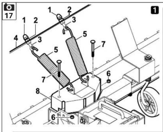
Removing the cover 1:
- Loosen and unscrew cap nuts (1).
- Loosen and unscrew nuts (2).
-
Pull studs (3) out from the respective bores in snow plough (4) and detach springs (5).
-
Loosen and unscrew both nuts (6). Remove bolts (7) and nuts (6).
- Remove cover (8) upwards.
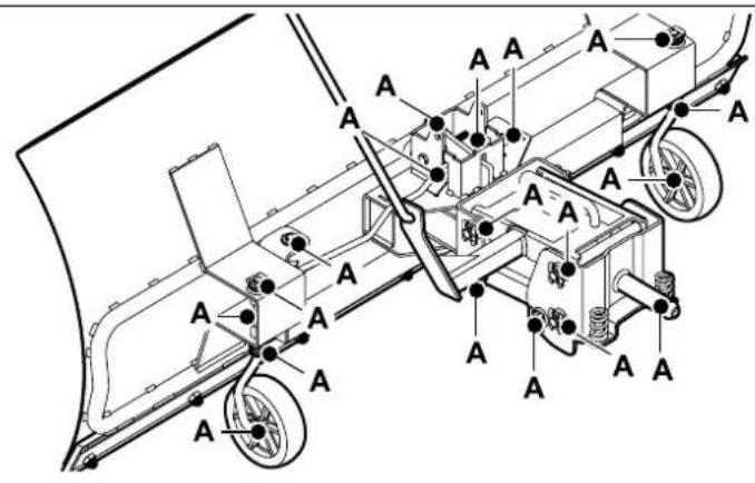
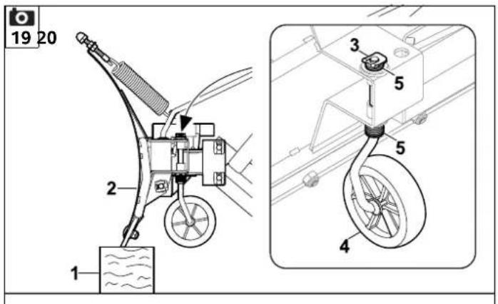
Lubricating the snow plough 2:
- Lubricate all lubrication points (A) on both sides with a commercially available lubricating grease spray.
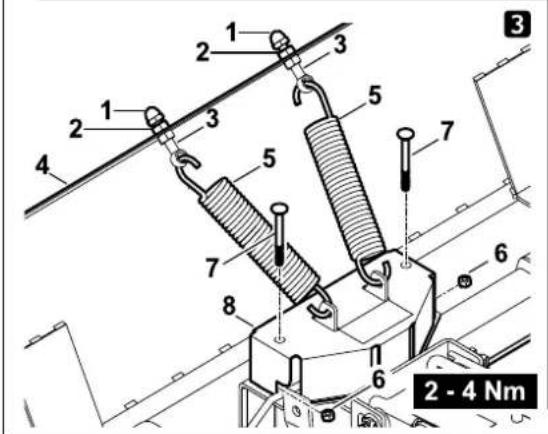
Installing the cover 3:
- Fit cover (8).
- Insert both bolts (7) through the bores from above and screw on nuts (6). Tighten nuts (6) to 2-4 Nm.
- Attach springs (5) and insert studs (3) through the respective bore in snow plough (4).
- Screw on nuts (2) and tighten.
- Screw on cap nuts (1) and tighten.
- Check the coil spring setting. (⇒ 15.2)
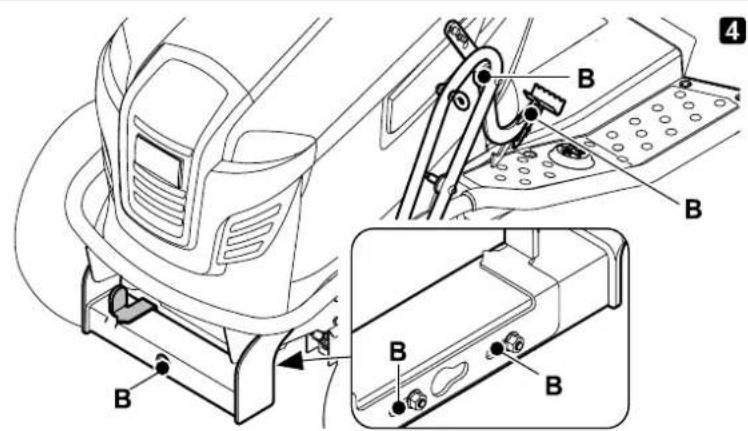
Lubricating the mounting frame 4:
- Lubricate all lubrication points (B) with a commercially available lubricating grease spray.

Note:
Remove excess grease and dispose of it in an environmentally-friendly way.
14.4 Reversing or replacing a slide bar


Note
In order for the snow plough to function optimally, the slide bar must be adjusted correctly. Reverse or replace a badly worn or damaged slide bar.
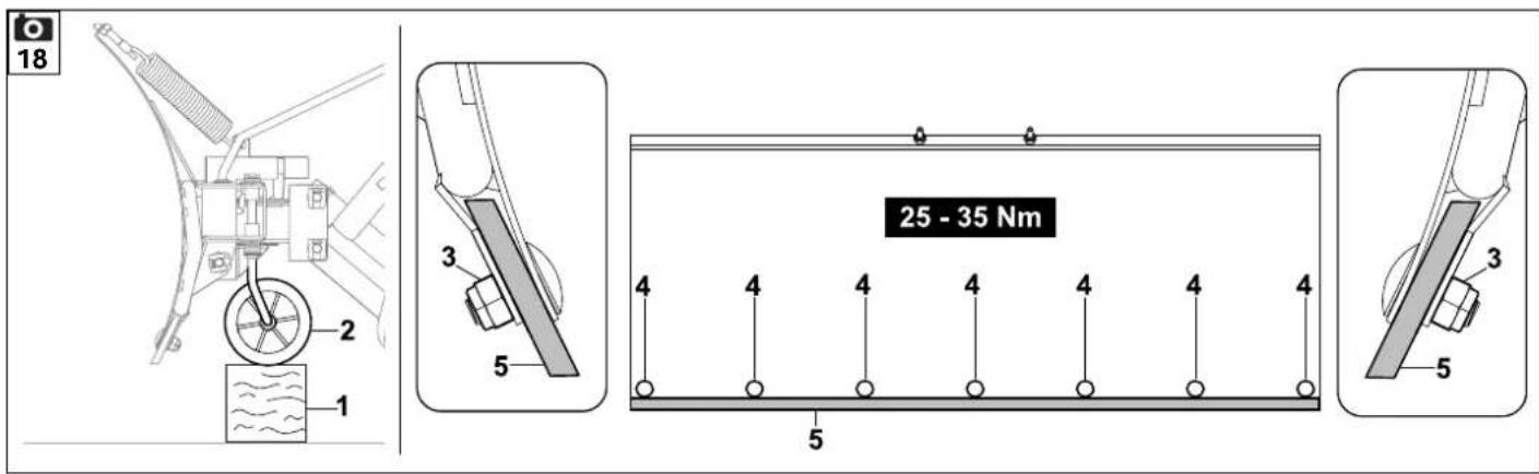
Removing the slide bar:
- Place the snow plough in the transport position.
- For safety, place a support (1) (e.g. piece of wood) under both gauge wheels (2) (right and left side of the snow plough).
- Unscrew nuts (3) and bolts (4) and remove slide bar (5).
Installing the slide bar:
- Reverse (worn edge upwards) or replace slide bar (5).
- Insert slide bar (5) so that the lower edge is parallel to the ground (note the position of the chamfer).
- Insert bolts (4) through the bores in the snow plough and slide bar (5). Screw on nuts (3) and tighten to 25-35 Nm.
- Place the snow plough in the transport position.
- Remove the support and lower the snow plough into the working position. (⇔ 13.3)
14.5 Adjusting the thrust spring


Note
The thrust spring must be adjusted in case of repair so that the snow plough can be installed correctly.
Adjusting the spring:
- Set the correct height by turning the screw. Both thrust springs must be installed in the same way.
Height: 22 mm
15. Adjusting the snow plough
15.1 Adjusting the gauge wheels


Note
The two gauge wheels must always be adjusted to be the same (discs in same arrangement) to guarantee safe and functional performance.
The higher the gauge wheels are adjusted, the greater the wear on the slide bar.
The slide bar must be checked and reversed or replaced if necessary before adjusting the gauge wheels. ( 14.4)
The height of the gauge wheels on delivery (gap between slide bar and ground) is the optimum setting to achieve the best possible performance.
Adjustment procedure:
- Place the snow plough in the transport position. (⇒ 13.2)
- Insert a parallel support (1) (e.g. wooden strip) along the entire width of the snow plough.
Lower snow plough (2) and ensure that the snow plough rests on the support with the slide bar.
- Pull off lock washer (3) at gauge wheel (4). Remove gauge wheel and washers (5) downwards. The gauge wheel height is determined by the arrangement of the washers (5).
- Repeat this procedure on the second gauge wheel.
- Place the snow plough in the transport position. ( 13.2)
- Remove the support and lower the snow plough into the working position. (⇒ 13.3)
15.2 Adjusting the coil springs
The coil springs act as a safety device.
If you hit an obstacle (e.g. pavement), the snow plough will swing forwards. This dampens the impact.


Risk of injury!
If the coil spring setting recommended by STIHL is changed so that the tension is increased, any impact will be harder.

Note
The setting must be the same for both coil springs. Do not use differing coil spring settings.
Recommended setting:
The optimum setting for both coil springs is slightly preloaded.
Adjustment procedure:
- Place the snow plough in the transport position. (⇒ 13.2)
- Loosen lock nut (2) while holding adjustment nut (1).
- Slightly preload the spring by turning adjustment nut (1).
- Tighten lock nut (2).
- Repeat this procedure on the other side.
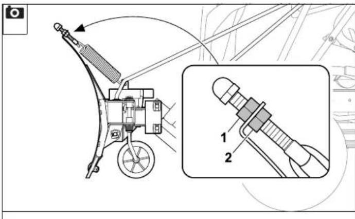
15.3 Adjusting the lift rod


Danger of crushing!
Lower the snow plough into the working position before performing any adjustments. ( 13.3)
The lift rod can be used to adjust the effort required to press the lift pedal.
Settings:
• Maximum lift position:
The lift rod (1) is attached to the top bore in the lift arm.
• Middle lift position:
The lift rod (1) is attached to the centre bore in the lift arm.
• Minimum lift position:
The lift rod (1) is attached to the bottom bore in the lift arm.
Adjustment procedure:
- Detach cotter pin (2) from lift rod (1).
- Position lift rod (1) as required in one of the three bores in lift arm (3) and fasten using cotter pin (2).

Note
The higher the lift rod setting, the more effort is required to press the lift pedal.
A lower lift rod setting reduces the lifting height of the snow plough.
16. Transport
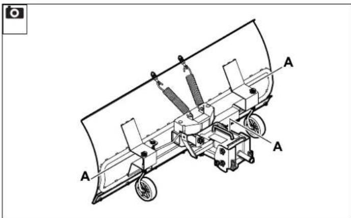
16.1 Lifting the snow plough


Risk of injury!
The snow plough should only be lifted with the help of a second person. Take account of the weight of the snow plough. ( 21.)
Do not hold the snow plough at moving parts when lifting it.
Always wear safety shoes with high-grip soles when lifting the snow plough.
- Hold the snow plough at handles (A) and lift.
16.2 Transporting the ride-on mower with installed snow plough

Risk of accident!
Before transport, carefully read and observe the section "For your safety". ( 4.)
Also observe the section "For your safety" in the instruction manual of the ride-on mower. If the ride-on mower with installed snow plough is transported on a load floor or a trailer, the snow plough must always be in the working position during transport. Take account of the overall weight when loading.
- Adjust the lift rod to the maximum lift position. ( 15.3)
- Place the snow plough in the transport position and drive onto the load floor with the ride-on mower. Then engage the parking brake. (⇔ 13.2)
- Lower the snow plough into the working position. ( 13.3)
- Secure the ride-on mower using adequately-dimensioned fastening materials (belts, ropes, etc.).
17. Standard spare parts
Slide bar: 6907 731 8305
Gauge wheels: 6170 704 9700
18. Accessories

Note
For safe and better operation of the ride-on mower during winter (different external conditions), additional accessories are recommended.
18.1 Snow chains
Snow chains improve the traction of the rear wheels on icy or snow-covered surfaces.
Snow chains, 16 inches ASK 016:
6907 730 3445
Snow chains, 18 inches ASK 018:
6907 730 3432
Snow chains, 20 inches ASK 020:
6907 730 3437

Note
Note that using snow chains can damage (scratch) the underlying surface (flagstones, asphalt, etc.).
19. Environmental protection
The machine, its packaging and accessories are all produced from recyclable materials and must be disposed of accordingly.
By disposing of materials separately and in an environmentally friendly manner, recyclable waste can be re-used. For this reason, the machine should be disposed of for recycling at the end of its useful life. Improper disposal may be harmful to health and pollute the environment. Pay particular attention to the information in the section "Disposal" during disposal. ( 4.5)
Consult your recycling centre or your specialist dealer for information on the proper disposal of waste products.
20. Declaration on the installation of an incomplete machine
STIHL Tirol GmbH
Hans Peter Stihl-Strasse 5
6336 Langkampfen
Austria
declares under our sole responsibility that the incomplete machine
snow plough,
manufacturer's
STIHL
brand:
type: ASP 100.1
serial number 6907
manufacturer's STIHL
brand:
type: ASP 125.1
serial number 6907
conforms to the following EC directives: 2006/42/EC
The versions of the standards valid on the production date apply to development and production of the products.
Compilation and storage of technical documentation:
Sven Zimmermann
STIHL Tirol GmbH
The year of manufacture and machine number appear on the rating plate of the machine.
The special technical documents have been drafted in accordance with Appendix VII Part B (2006/42/EC).
National authorities will be provided with the special documents regarding the incomplete machine in printed or digital form upon well-founded request.
The snow plough may only be operated if the ride-on mower is in good operating condition. The safety instructions in the relevant instruction manual must be observed.
Langkampfen,
2022-01-02 (YYYY-MM-DD)
STIHL Tirol GmbH
p.p.

Matthias Fleischer, Research and Development Division Manager
p.p.

Sven Zimmermann, Quality Division Manager
21. Technical specifications
ASP 100.1:
Snow plough width 1000 mm
Snow plough height 500 mm
Working width in cen-
tre position 1000 mm
Working width in
angled position 872 mm
Weight 46 kg
ASP 125.1:
Snow plough width 1250 mm
Snow plough height 500 mm
Working width in cen-
tre position 1250 mm
Working width in
angled position 1088 mm
Weight 50 kg
Dimensions:
ASP 100.1:
Overall length: 637 mm
ASP 125.1:
Overall length: 637 mm
22. Troubleshooting
✗ If necessary, contact a specialist dealer; STIHL recommends STIHL specialist dealers.
Fault:
RT 5097/ C/ Z, RT 5112 Z,
RT 6112 C/ ZL, RT 6127 ZL:
Starter not functioning. It is not possible to start the engine.
Possible cause:
- The cover is not installed (when using the snow plough).
- The safety devices are blocking the starter.
Remedy:
- Install the cover. (⇔ 9.1)
- Check the safety devices (see instruction manual for the ride-on mower).
Fault:
Poor clearing performance.
Possible cause:
– Amount of snow is too great.
Remedy:
- Reduce clearing width or mount snow chains (not included in standard equipment).
Fault:
Poor or no traction at rear wheels.
Possible cause:
- Amount of snow is too great.
Remedy:
- Reduce clearing width or mount snow chains (not included in standard equipment).
Chère cliente, cher client,
large entrée, parking, cour, etc.
Conseils :
- Monteer de afdekking. (⇒ 9.1)
Kjøre (hydrostatgir):

Merknad
Kjøre (manuelt gir):

Merknad
7.4 Montera ram, variant 2

Demonter glideskinne:
0478 907 9930 A