WOOB-4001400 - Machine tool MSW - Free user manual and instructions
Find the device manual for free WOOB-4001400 MSW in PDF.

| Product type | Wood router |
| Brand | MSW |
| Model | WOOB-4001400 |
| Supply voltage | 400 V ~ three-phase, 50 Hz |
| Rated power | 1500 W |
| Rotation speeds | 1400 / 4000 / 6000 / 9000 rpm |
| Spindle diameter | 30 mm |
| Max cutter diameter | 160 mm |
| Milling stroke | 0-105 mm |
| Table dimensions | 600 x 400 mm |
| Sliding table dimensions | 1000 x 218 mm |
| Overall dimensions (L x W x H) | 1045 x 710 x 1230 mm |
| Net weight | 95 kg |
| Extraction connection | Diameter 100 mm |
| Minimum extraction flow | 570 m³/h (dry) / 790 m³/h (wet) |
| Sound pressure level (no load) | 81.7 dB(A) |
| Sound pressure level (under load) | 89.5 dB(A) |
| Application | Longitudinal and cross shaping of wood |
| Safety | Protective cover, integrated emergency stop |
| Maintenance | Weekly cleaning, monthly lubrication |
| Spare parts | Available on request |
Frequently Asked Questions - WOOB-4001400 MSW
User questions about WOOB-4001400 MSW
0 question about this device. Answer the ones you know or ask your own.
Ask a new question about this device
Download the instructions for your Machine tool in PDF format for free! Find your manual WOOB-4001400 - MSW and take your electronic device back in hand. On this page are published all the documents necessary for the use of your device. WOOB-4001400 by MSW.
USER MANUAL WOOB-4001400 MSW
natural_image
Technical line drawing of a mechanical machine with no visible text or symbolsnatural_image
Technical line drawing of a mechanical assembly with labeled component A (no text or symbols beyond label)A- Einlaufanschlag
natural_image
Line drawing of a hand operating a mechanical device with a tool handle (no text or symbols)A- Kutter
B- Hinterer Zaun
C- Schnitttiefe
D- Futtermittel
E- Arbeit
F- Vorderer Zaun
G- Schnittkreis
A- Kutter
B- Hinterer Zaun

natural_image
Close-up of a mechanical optical device with no visible text or symbolsThis User Manual has been translated using machine translation. We have made every effort to ensure the translation is accurate, but please note that automated translations are not perfect and are not meant to replace human translators. The official version of the User Manual is in English. Any differences between the translated version and the original English are not legally binding. If you have any questions about the accuracy of the translation, please refer to the English version, which is the official reference. More language versions are available upon request via info@expondo.com.
Technical data
| Parameter description Parameter value | |
| Product name Spindle moulder | |
| Model | MSW-WOOB-4001400 |
| Rated voltage [V~, N] / frequency [Hz] 400, 3 / 50 | |
| Rated power [W] 1500 | |
| IP | 20 |
| Milling speed [/min] 1400/4000/6000/9000 | |
| Spindle [mm] 30 | |
| Max cutter [mm] 160 | |
| Milling travel [mm] 0-105 | |
| Table size [mm] 600*400 | |
| Sliding table size [mm] 1000*218 | |
| Dimensions [width * length * height; mm] 1045*710*1230 | |
| Weight [kg] 95 | |
Description
natural_image
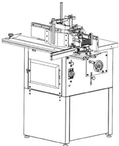
Technical line drawing of a mechanical machine with no visible text or symbolsThe machine enables lengthwise as well as crosswise moulding with a vertical spindle of semi-finished products made of wood or of materials based on wood. The machine is designed for operation performed by one worker only.
The machine is not intended nor designed for curved work and must not be used for curved work. There is no tenoning function. The machine is designed solely for straight work.
The user is liable for any damage resulting from unintended use of the device.
Technical specifications
| Level of noise A in the place of operation (LpAeq) | No-load | LpAeq =81.7 dB(A) |
| Load | LpAeq =89.5 dB(A) | |
| Level of acoustic power A (LWA) | No-load | LWA = 94.5 dB(A) |
| Load LWA = 103 dB(A) | ||
Operating conditions for noise measurement comply with annex B of ISO 7960.
The figures quoted are emission levels and are not necessarily safe working levels. Whilst there is a correlation between the emission and exposure levels, this cannot be used reliably to determine whether or not further precautions are required.
Factors that influence the actual level of exposure of the workforce include the characteristics of the work room, the other sources of noise etc., i.e. the number of machines and other adjacent processes. Also the permissible exposure level can vary from country to country. This information, however, will enable the user of the machine to make a better evaluation of the hazard and risk. Transport and storage
Installation
Connection of the exhaustion system
Work on the machine only with the exhaustion system connected and running! For the proper functioning of the machine, exhaustion equipment with minimum exhaustion capacity of 570 m ^3 /hour and minimum speed of air in the pipes equal to 20m/s for dry particles and 790 m ^3 /hour and minimum speed of air in the pipes equal to 28m/s for wet particles is necessary.
Switch on the machine drive and exhaustion system at the same time!
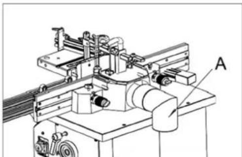
Use flexible exhausting hoses with diameters equal to 100 mm The exhausting hose is connected to exhausting outlet whose location on machine is as follows:
For the moulding machine the exhausting hose is fitted onto the outlet from the moulding tool cover which also forms the exhausting connector (A). The hose diameter is 100 mm.
natural_image
Technical line drawing of a mechanical assembly with labeled component A (no text or symbols beyond label)Connection to the mains
- Damaged power supply cables must be replaced by a competent specialist immediately. Operation with damaged cables is dangerous to life and is therefore forbidden!
- Before putting the machine into operation make sure that the voltage and frequency specified on the machine type plate comply with the values of the mains to which it is connected.
• Over voltage protection shall be provided by the end user. - Before adjustment and replacement of tools and before any adjustment work, alterations and maintenance work, always turn off the switch and disconnect the plug from supply socket.
- This machine must be connected to the protection earth. Inspect and be sure that the socket is reliably earthed.
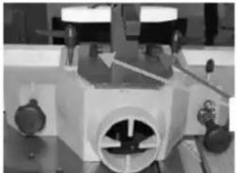
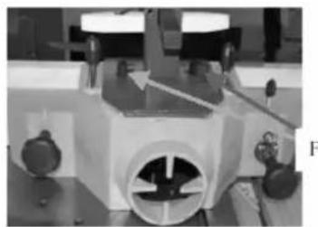
Direction of rotation
If you are standing on the side of the machine and viewing from the upper of the table, the moulder spindle rotates anticlockwise if you look down.
Operation
Preparation
Remove the protective coating from the working tables and other parts of the machine either with paraffin oil or any similar solvent, do not use petrol or similar solvents for this activity –they might cause reduced corrosion resistance of certain parts of the machine.
The working area size depends on the type of the machine, assumed working operations and size of material machined.
Do not forget about the space for location of a sufficiently effective exhausting system or connecting hoses for the central exhaustion.
Workers' qualifications
Only an expert skilled in the field of wood-machining or a worker instructed and trained by such expert may operate the machine, regardless of the gender. While working on the machine the operator must get familiar with these instructions and comply with any safety rules, regulations and provisions in force in the respective country.
Working environment
The machine must be operated in a workshop environment the temperature of which does not exceed +40°C and does not drop below +5°C. The relative humidity of ambient is from 30% to 95%, non-condensing. The height above the sea level is up to 1000 m.
Storage and transportation temperature: -25\~+55°C
The environment classification - danger of inflammable dust fire.
Working area
It is important to maintain free area of 0.8 m around the machine, which is required for the working place. If any long material is machined, it is necessary to have a sufficient room in front of the machine as well behind it in the places of material input and output.
Adjusting the machine
Set the height of the moulding spindle by means of the hand wheel located on the rear right side of the stand and secure it with the arresting screw. Select the suitable filler of the table (table ring) according to the tool used.
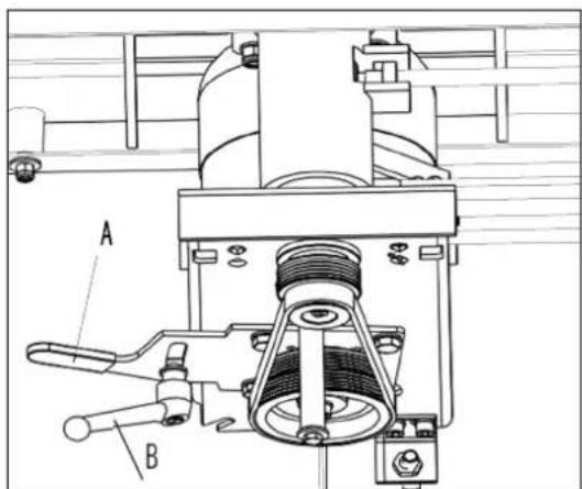
Speed change
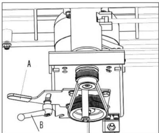
The machine may be operated at 6,500 RPM (lower pulleys) or 4,500 RPM (upper pulleys). To change the spindle speed, loosen the lock handle (A) and pivot the motor assembly toward the spindle. Reposition the belt to the desired speed and tension the knob (B).
Lengthwise moulding
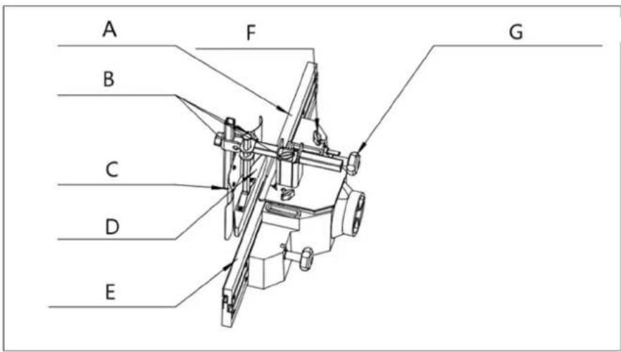
A- Infeed fence
B- Locking knob
C- Pressure pad
D- Pressure pad
E- Outfeed fence
F- Fine adjusting handle
Tool: use suitable tools with a defined thickness of the chip for manual feeding. Working cycle: while test moulding is being performed, start working with a workpiece with sufficient length, width and height. It is necessary to prevent blocking of the machine, or to use a security against kick-back adapted to the workpiece dimensions. In order to prevent kickback it is necessary to use back and/or front end stops fixed to the fence, table or fixed to and extension table.
Never set the rulers while the machine is being operated!
While working, perform the lateral adjustment of the fence plates, keep the opening for the tool to be reduced to a minimum, lock the fence plates and adjust the fine adjusting handle to set the required chip (wood removal) and lock the station by the locking knob.
Keep the pressure pads in contact with the table and the fence plates firmly and evenly along the guide ruler.
The cutting speed shall exceed 40ms^-1 in order to lessen the risk of kickback but shall not exceed 70ms^-1 in order to lessen the risk of tool damage.
Adequate general or localised lighting shall be provided.
Moulding of workpieces with small cross-section
Tool : Choose the tool suitable for manual feeding.
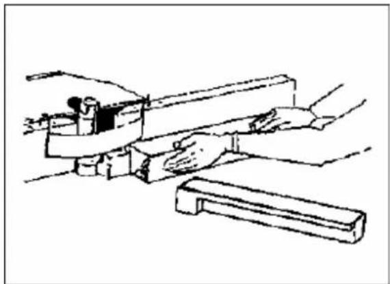
natural_image
Line drawing of a mechanical assembly or tool with no visible text or symbolsWorking cycle: Adjust the moulding machine and put both halves of the ruler close to the tool. Machine the material only by means of a pusher! Choose the size of the pusher so that the hand may be put on it comfortably.
Protective aids
For work on the machine eye protection are prescribed. It is advisable to use appropriate ear protection and commended working shoes. Working overall coats are not allowed to use.
Handlings NOT allowed
On the machine, it is NOT allowed to:
- Perform any alteration of the machine safety items without the manufacturer's permission.
• Perform any manipulation inconsistent with safety instructions in this handbook. - Touch the tool or its close surrounding places and other moving parts.
• Machine any materials other than wood or those based on wood.
• Overload the machine while machining large semi-finished products. - Remove chips from the place near the tools by hand or with any object while the machine is being operated.
• Use other tools than those delivered or recommended by the machine manufacturer.
Using the fence as a guide
Shaping with the fence is the safest and most satisfactory method of working. This method should always be used when work permits. Almost all-straight work can be used with the fence.
- For most work, where a portion of the edge of the work is not touched by the cutter, both the front and rear fences are in a straight line, as shown in the below figure.
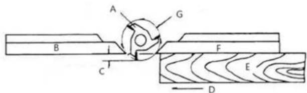
A- Cutter
B- Rear fence
C- Depth of cut
D- Feed
E- Work
F- Front fence
G- Cutting circle
- When the shaping operation removes the entire edge of the work (i.e. jointing or making a full bead), the shaped edge will not be supported by the rear fence when both fences are in line as shown in the below figure. In this case, the workpiece should be advanced to the position shown in in the below figure and stopped.
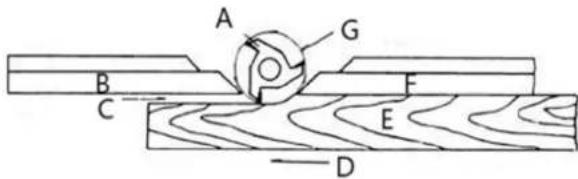
A- Cutter
B- Rear fence
C- No support
D- Feed
E- Work
F- Front fence
G- Cutting circle
- The front fence should be advanced to contact the work as shown in the below figure. The rear fence will then be in line with the cutting circle.
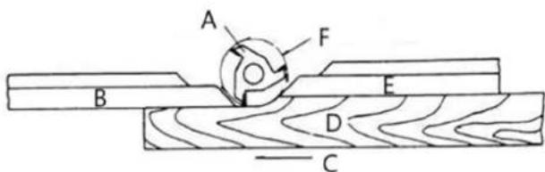
A- Cutter
B- Rear fence
C- Feed
D- Work
E- Front fence
F- Cutting circle
Shaping with collars
Follow these rules when shaping with collars for safest operation and best results:
- Collars must be smooth and free from all gum or other substances.
- The edge of the work must be smooth. Any irregularity in the surface, which rides against the collar, will be duplicated on the shaped surface.
- A portion of the work's edge must remain untouched by the cutter so that the collar will have sufficient bearing surface. See the below figure for an example of insufficient bearing surface.
F
A- Collar
B- Cutter
C- Table
D- Work
E- Not sufficient bearing surface
F- Wrong
- The below figure illustrates sufficient bearing surface.
F
A- Collar
B- Cutter
C- Table
D- Work
E- Sufficient bearing surface
F- Right
- Under no circumstances should a small workpiece be shaped against the collars as shown in the below
figure.
E
A- Collar
B- Cutter
C- Table
D- Narrow workpiece
E- Wrong
Collar positioning
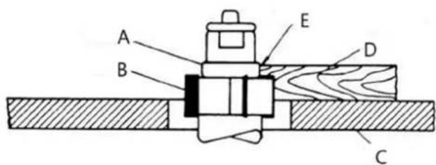
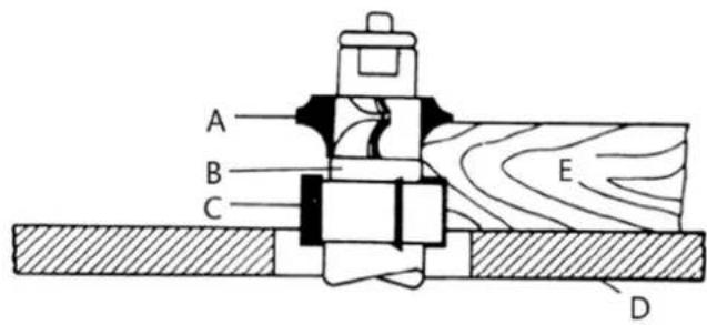
Collars may be positioned above, below, or between two cutters:
- When using the collar below the cutter, the below figure, the progress of the cut can be observed at all times. A disadvantage of this method is any accidental lifting of the work will gouge the wood and ruin the workpiece.
A- Cutter
B- Collar
C- Table
D- Work
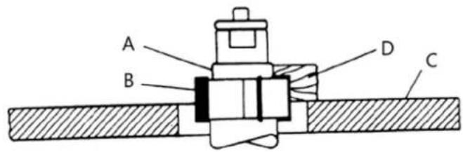
- Using the collar above the cutter, the below figure, offers the advantage of the cut not being affected by slight variations in the stock's thickness. However, the cut is not visible during the operation. Another advantage is accidental lifting of the work piece will not gouge the work piece. Simply correct the mistake by repeating the operation.
A- Collar
B- Cutter
C- Table
D- Work
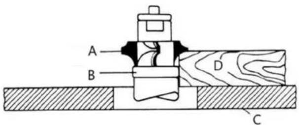
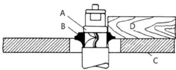
- The collar between cutters method, shown in the below figure, has both the advantages and disadvantages of the first two methods. This method is used primarily where both edges of the work are to be shaped. The machine can not be used for tenoning!
A- Cutter
B- Collar
C- Cutter
D- Table
E- Work
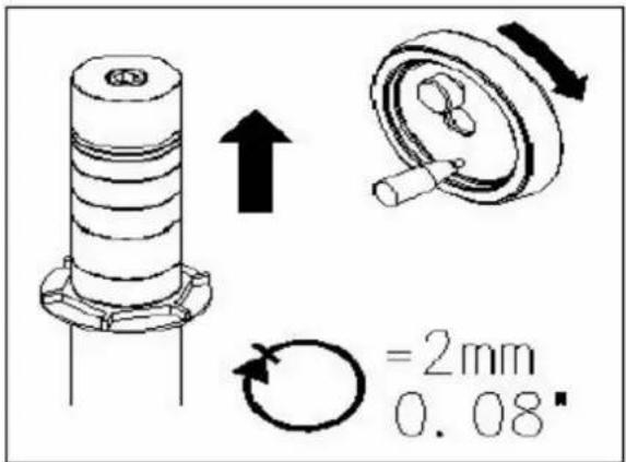
Replacement of moulding tools
Only use moulding tools that are designed for manual feeding and may be clamped firmly and safely. Only tools conforming to EN847-1:2005 and marked MAN shall be used.
natural_image
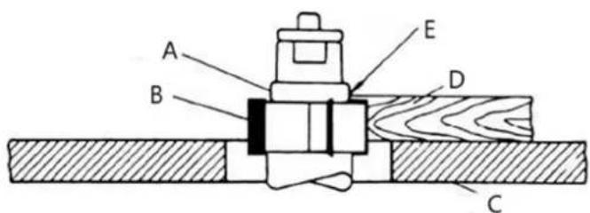
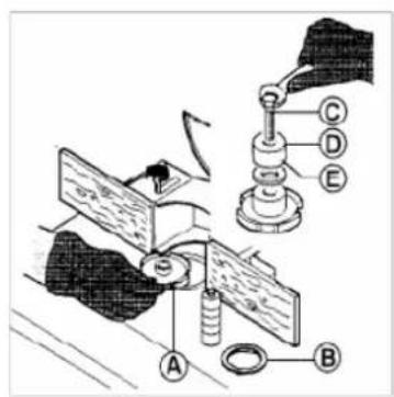
Close-up of a mechanical optical or laser device with no visible text or symbolsBefore mounting tool (A) make sure that spacing rings (E) are clean and not damaged. Make sure that the fastening method is proper. The moulding tool is fixed and clamped by bolt (nut) (C), through spindle ring (D) and spacing rings (E) on the moulding spindle! Adjust the hole in the table according to the diameter of moulding tool (A) by table rings (B).
When installing the moulding tools, the cover of guard needs to be opened. Loose the two locking knobs (F) to open the cover. After installation, close the cover and lock it through the locking knobs.

WARNING! Always close the cover of guard and lock it securely after the tools are installed.
Transportation and storage
Transportation and storage
While transporting or handling the machine, be most careful and let this activity be done by qualified personnel especially trained for this kind of activity.
While the machine is being loaded or unloaded, make sure that no person or subject gets pressed by the machine!
Do not enter the area under the machine lifted by a crane or a high-lift trolley!
During transporting or storing the machine, means must be taken to protect the machine against excessive vibrations and humidity.
It should be stored in a shelter at temperatures ranging from -25^ to 55^ . As standard, the machine is wrapped up in a plastic tray and is transported this way. Upon request, the machine may also be packed in a robust wooden box.
Lifting of the machine
The machine or its individual parts may only be lifted by means of an approved lifting device with verified lifting capacity.
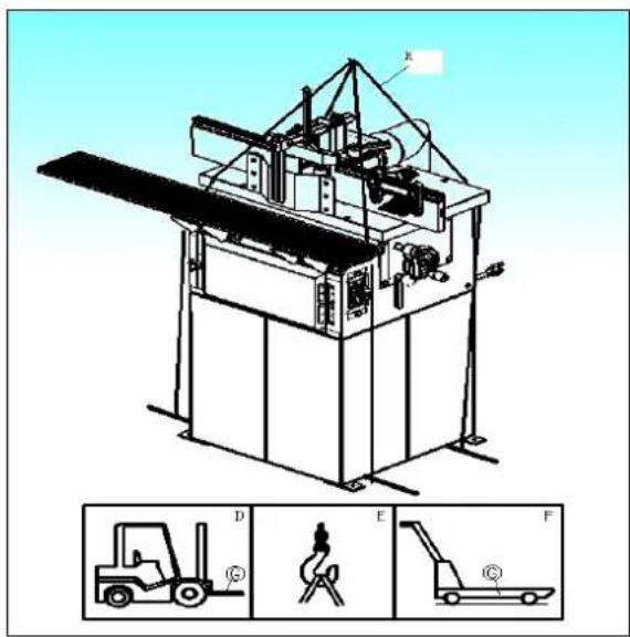
Prepare a high-lift truck (D) or a manual lifting carriage (F) with sufficient lifting capacity, put the forks (G) below the machine, as shown in the picture.
Should you use a crane (E) or a similar hoisting equipment, proceed as follows:
• Prepare four lifting belts (H) or steel ropes at least 2 m long with sufficient lifting capacity.
• Fix the ropes to the hook of the crane with the required capacity.
- Place the other end of the ropes on the lifting rods put under the machine (rods are not part of delivery).
• After lifting the machine slightly, check the stability of the machine hanging on the ropes.
- Lift the machine carefully and slowly and then move it without any rapid changes of the movement to the selected place.
Maintenance
Before starting maintenance or repair work always disconnect the machine from the mains! Turn off the machine and remove the plug from the supply socket!
Always keep the V-belts (transmission belt for spindle) tight is necessary.
The machine should be cleaned. The rods, pins, threads and other parts liable to be rusty should be lubricated with suitable oil. The interval for such activities will depend on the manner of work but it should be performed at least once a month.
The bearings of the electrical motors and moulding spindle have permanent grease filling, are closed on both sides and do not require any lubrication.
Avoid contamination of belts with oil or grease. If this occurs, clean the belt with paper only or dry it.
Removing the dust is best to be done with a vacuum cleaner. Perform this activity regularly, at east once a week.
Troubleshooting
No faults should occur while the machine is used correctly and maintained duly. If the exhausting hose is blocked with chips, the machine should be switched off before handling. If a workpiece becomes jammed, turn off the machine immediately! A blunt knife often causes that the electric motor to become heated excessively. If the machine vibrates excessively, check its setting and anchoring, possibly also clamping and balancing of the tools used.
| Problem | Possible | cause |
| Shaper will not start | Fuse blown or circuit breaker tripped | Replace fuse or reset circuit breaker |
| Cord damaged Replace cord | ||
| Cord unplugged from the power source | Plug in power cord | |
| Reversing switch is in the OFF position | Turn switch to forward or reverse | |
| Overload kicks out frequently | The extension cord or wiring inadequate size | Replace cord or wiring with proper gauge wiring |
| Feeding stock too fast Reduce stock feed rate | ||
| Cutter head is dull Use only sharp cutters | ||
| Cutter does not come up to full speed | Shop wire gauge is too small | Replace cord or wiring with proper gauge wire |
| Extension cord too light or too long Replace with adequate size cord | ||
| Power source is not adequate | Contact local electrical utility | |
| Cuts are unsatisfactory | Dull cutter | Replace cutter |
| Gum or pitch on cutter | Remove cutter and clean with solvent | |
| Cutterhead rotating in the wrong direction | Check for proper rotation at start up | |
| Feeding work in the wrong direction Feed work against the cutter rotation | ||
| Machine vibrates | Cutterhead damaged | Replace cutterhead |
| Stand on an uneven surface | Stand must rest solidly on level surface, bolt to floor if necessary | |
| Defective V-belt Replace V-belt | ||
| V-belt incorrectly tensioned Apply proper tension | ||
| Bent pulley Replace pulley | ||
| Motor mounted improperly | Motor must be properly mounted with snug nuts and bolts | |
| Edge splits off on cross grain cut | Characteristic of this type of cut | Make cross-grain cuts first, then finish cut with the grain |
| Use scrap block to support end of cut | ||
| Raised areas on shaped edge | Variation of pressure holding work against cutter | Hold work firmly against table and fence |
| Use hold-downs | ||
| Work pulled from hand Feeding work in the wrong direction | Always feed work against the rotation of the cutterhead | |
| Depth of cut not uniform | Fence misalignment Align outfeed fence | |
| Side pressure not uniform | Use hold-downs: keep constant pressure against fence | |
| Work burns | Cutting too deep on one pass | On hardwoods take light cuts; attain full depth with several passes |
| Forcing work Feed work slowly and steadily | ||
| Cut height not uniform | Variation in pressure holding work to table | Keep pressure firm throughout pass |
| Use hold-downs | ||
| Make pass slowly and steadily | ||
| Keep work under cutter whenever possible | ||
| Cuts not smooth | Wrong R.P.M. Use faster speed | |
| Feeding too fast Slow feed speed | ||
| Working against the grain | Work with the grain whenever possible | |
| Cutting too deep on one pass Take several passes on very deep cuts | ||
| Spindle does not raise freely | Sawdust or dirt in the raising mechanism | Brush or blow out dirt and saw dust |
Disposing of used devices
Do not dispose of this device in municipal waste systems. Hand it over to an electric and electrical device recycling and collection point. Check the symbol on the product, instruction manual, and packaging. The plastics used to construct the device can be recycled following their markings. By choosing to recycle you are making a significant contribution to the protection of our environment.
Contact local authorities for information on your local recycling facility.
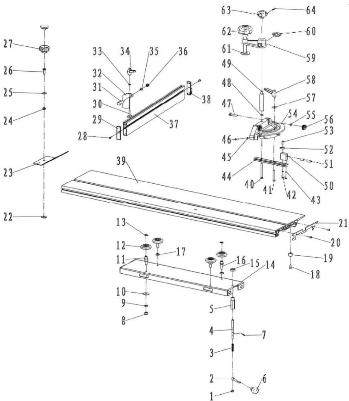
Parts diagram
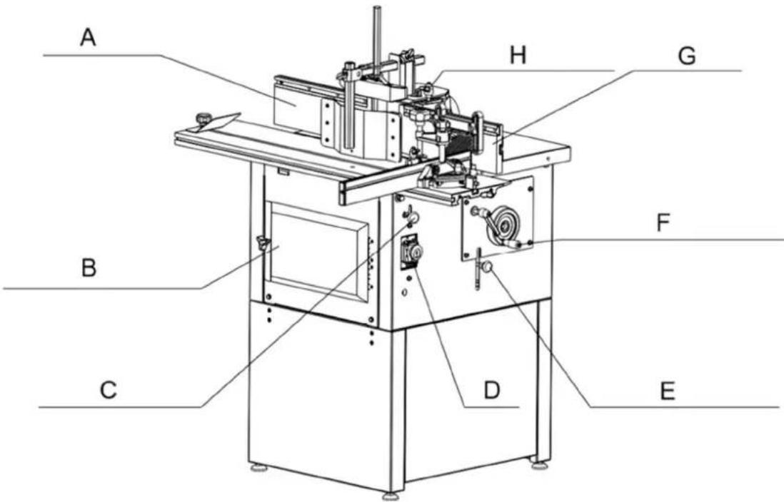
Features
| Part number Description | |
| A | Outfeed |
| B | Motor |
| C | Sliding |
| D | Switch |
| E Spindle rotation lock | |
| F Spindle rise & fall control | |
| G | Infeed |
| H Fence securing bolt |
f
compartment table
f
Final assembly
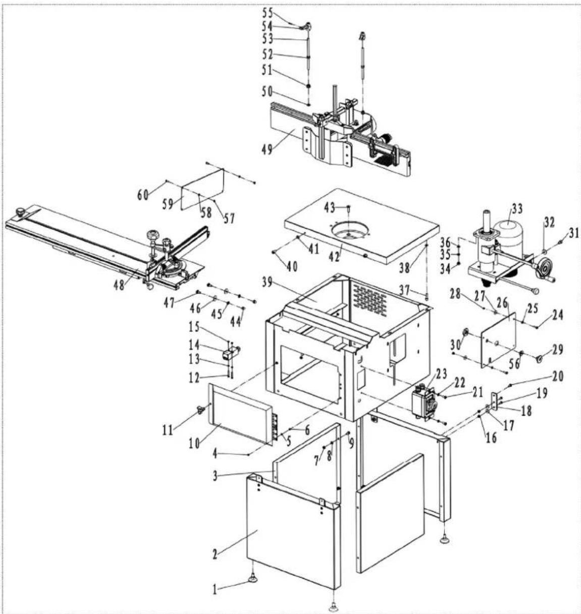
| NO. | DESCRIPTION | NO. | DESCRIPTION |
| 1 | Underprop | 2 | |
| 3 | Cover | board | 4 |
| 5 Washer 4 6 Hex nut M4 | |||
| 7 Hex nut M6 8 Washer 6 | |||
| 9 Hex bolt M6X16 10 Protective cover | |||
| 11 | Door | knob | 12 |
| 13 | Washer | 4 | 14 |
| 15 | Hex nut M4 | 16 | Hex nut M6 |
| 17 | Large washer 6 | 18 | Linking plate |
| 19 | Screw M6X16 | 20 Hex bolt M6X12 | |
| 21 | Screw M6X16 | 22 | Washer 6 |
| 23 | Switch assembly | 24 Screw M6) | |
| 25 | Washer | 6 | 26 |
Lower Screw
Screw Interl
Moulding
| 27 Large washer 6 28 Hex nut M6 | ||
| 29 Bush | 30 Hex | |
| 31 Screw M8X25 32 Large washer 8 | ||
| 33 Moulder assembly 34 Hex nut M8 | ||
| 35 Spring washer 8 36 Washer 8 | ||
| 37 Screw M8X25 38 Washer 8 | ||
| 39 Box assembly | 40 | |
| 41 Washer | 8 | 42 |
| 43 Screw M8X30 44 Dome hex nut M8 | ||
| 45 Dentiform washer 8 | 46 Large washer 8 | |
| 47 Square neck bolt M8X16 | 48 Sliding table assembly | |
| 49 Exhaustion socket assembly | 50 Washer 8 | |
| 51 Hex flange nut M8 52 Hex nut M8 | ||
| 53 Locking shaft | 54 Locking handle | |
| 55 Spring pin 3X16 56 | bush | |
| 57 Hex nut M5 | 58 Washer 8 | |
| 59 Window plate | 60 Screw M5X12 |
Moulding spindle unit assembly
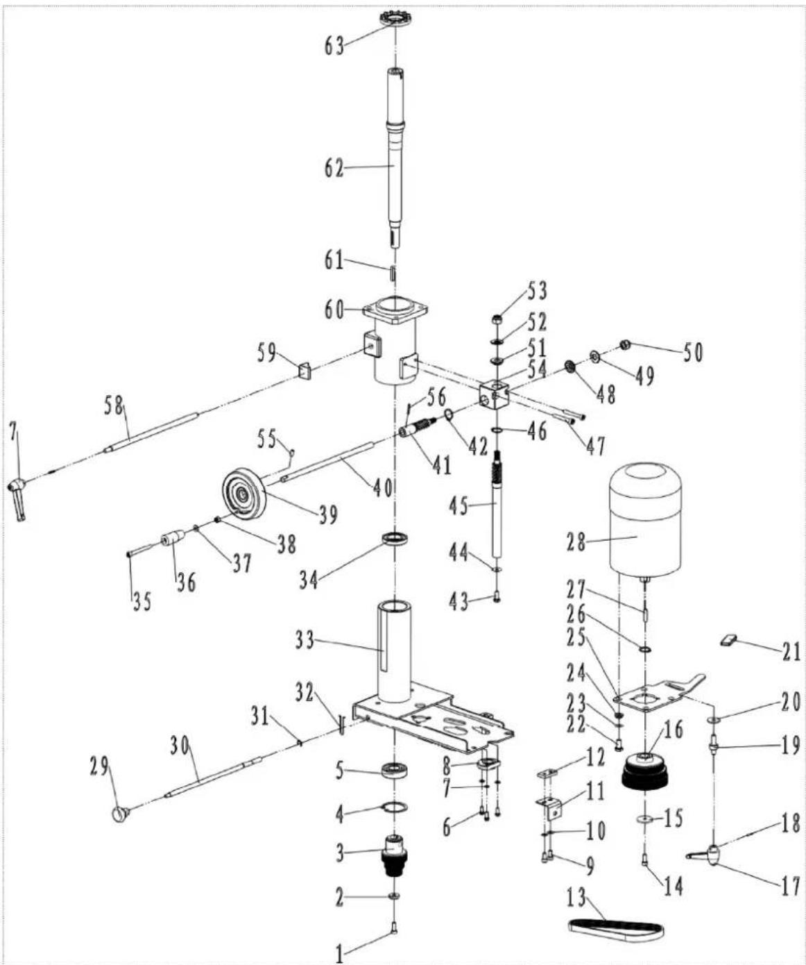
| NO. | DESCRIPTION | NO. | DESCRIPTION |
| 1 | Screw M6X16 | 2 | Circular |
| 3 Driven pulley 4 “C” ring φ47 | |||
| 5 | Bearing | 6204 | Hex |
| 7 Washer 5 8 Nut bush | |||
| 9 Screw M6X14 10 Washer 6 | |||
| 11 | Angle plate | 12 | |
| 13 Cuneal bel 14 Screw M6X16 | |||
| 15 | Large washer | 16 | Motor |
| 17 | Locking handle | 18 | Spring pin 3X16 |
| 19 | Locking bolt | 20 | Large washer 8 |
| 21 | Handle | coat | 22 Hex |
| 23 | Washer 8 | 24 | Space bush |
| 25 | Rotation plate | 26 | “C” ring φ19 |
| 27 | Key | 6X25 | 28 |
| 29 | handgrip | 30 | Locking |
| 31 | “E” ring 6 | 32 | Spring |
| 33 | Motor | rack | 34 Bearing |
| 35 Screw M6X60 36 Handle bush | |||
| 37 | Washer | 6 | 38 Hex |
| 39 Hand wheel 40 Rotation pole | |||
| 41 | Gear | shaft | 42“C” ring 18 |
| 43 Hex bolt M6X16 44 Large washer 6 | |||
| 45 | Gear | shaft | 46“C” ring 18 |
| 47 | Screw M6X45 | 48 | |
| 49 | Bearing | 50 | Hex locking nut M10 |
| 51 | Gear bush | 52 | Bearing |
| 53 | Hex locking nut M10 | 54 | Gear |
| 55 | Set screw M6X12 | 56 | Spring pin 3X20 |
| 57 | Locking handle | 58 | Locking pole |
| 59 | Locking block | 60 | Oriented stand |
| 61 | Key | 5X30 | 62 Spir |
| 63 | Fan cap | ||
pole clip
Gear
box
Moulding exhaustion socket assembly
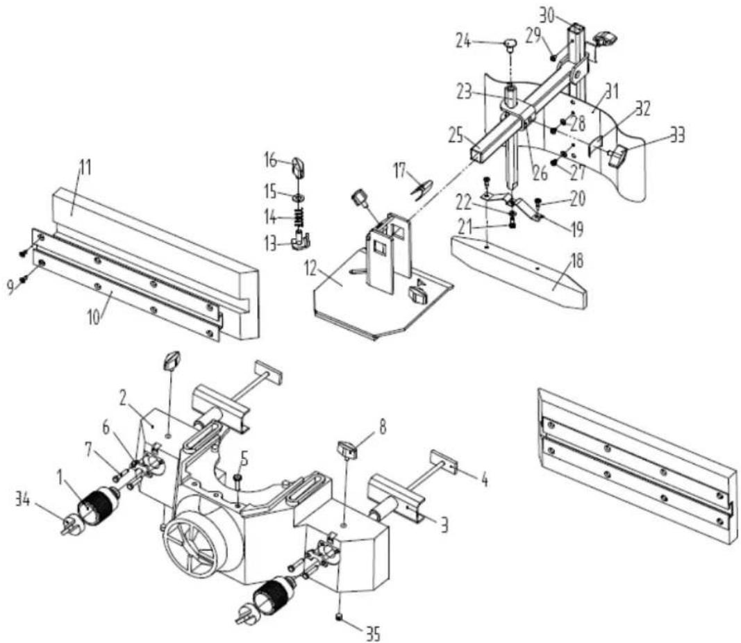
| NO. | DESCRIPTION | NO. | DESCRIPTION |
| 1 | Adjusting wheel | 2 | Exhaustion socket |
| 3 | Guide rack | 4 | T-shaped bolt |
| 5 | Screw | M6X10 | 6 |
| 7 Hex bolt M5X12 8 Rhombic handgrip | |||
| 9 | Screw | M4X12 | 10 T-shaped |
| 11 | Horizontal wood broad | 12 | Turing |
| 13 | Locking sheet | metal 14 | |
| 15 | Washer 8 | 16 | Rhombic handgrip |
| 17 | Saucer | 18 | Horrent |
| 19 M-shaped plate 20 Screw M4X16 | |||
| 21 | Hex bolt M5X12 | 22 | Washer 5 |
| 23 | Hexangular leader | 24 | Bolt M8X10 |
| 25 | Square leader assembly | 26 | Capstan |
| 27 | Screw | M4X6 | 28 Washer 4 |
| 29 | Screw | M4X6 | 30 Standpipe |
| 31 | Spring protective broad | 32 | Locking patch |
| 33 | Rhombic handgrip | 34 | Locking knob |
| 35 Set screw M8X10 | |||
Meta
wood
Sliding table assembly
| NO. | DESCRIPTION | NO. | DESCRIPTION |
| 1 Hex nut M6 2 Pin pole | |||
| 3 | Spring | 4 Locking | |
| 5 Pole bush 6 Locking handle | |||
| 7 Spring pin 3X16 8 Hex nut M8 | |||
| 9 Dentiform washer 8 10 Large washer 8 | |||
| 11 | Eccentric pole | 12 Trolley | |
| 13 | “C” ring 10 | 14 | Table support |
| 15 | Hex thin nut M12 | 16 | Homocentric pole |
| 17 | Hex thin nut M8 18 Screw M6X16 | ||
| 19 | Nylon bush | 20 Screw M4X10 | |
| 21 Guide rail insert 22 Square nut | ||
| 23 Stopping plate 24 Hex nut M6 | ||
| 25 Large washer 6 26 Hex bolt M6X20 | ||
| 27 Handle assembly 28 Screw M4X10 | ||
| 29 Fence insert | 30 | |
| 31 Stopping bolt 32 Locking plate | ||
| 33 Washer 5 | 34 Small handle | |
| 35 Washer 6 | 36 Locking hex nut M6 | |
| 37 Fence | 38 Fence insert | |
| 39 Guide rail | 40 Screw M6X70 | |
| 41 Screw M6X50 42 | Screw M4X12 | |
| 43 Spring washer 4 44 | T-shaped plate | |
| 45 Hex nut M4 46 | Screw M4X16 | |
| 47 Square neck bolt M6X30 | 48 Washer 6 | |
| 49 Erection shaft | 50 Fixed support | |
| 51 Stopping pole | 52 pointer | |
| 53 Screw M4X12 | 54 Miter gauge | |
| 55 Washer 6 | 56 Locking button | |
| 57 Large washer 6 58 Small handle | ||
| 59 Rocker | 60 Rhombic handgrip | |
| 61 Press plate 62 | Press handle | |
| 63 Handle | 64 Spring pin 3X16 | |

natural_image
Technical line drawing of a mechanical machine assembly (no text or symbols visible)natural_image
Technical line drawing of a mechanical assembly with labeled component A (no text or symbols beyond label)natural_image
Line drawing of a mechanical assembly or tool with no visible text or symbolsA- Nóž
B- Plot tylny
C- Głębokość cięcia
D- Karmić
E- Praca
F- Płot przedni
G- Krag tnacy
A- Nóž
B- Plot tylny
C- Brak wsparcia
D- Karmić
E- Praca
F- Płot przedni
G- Krag tnacy

natural_image
Close-up of a mechanical optical device with no visible text or symbolsnatural_image
Technical line drawing of a mechanical machine with no visible text or symbolsnatural_image
Technical line drawing of a mechanical assembly with labeled component A (no text or symbols beyond label)Změna rychlosti
natural_image
Line drawing of a mechanical assembly or tool with no visible text or symbolsA- Stolní kutr
B- Zadní plot
C- Hloubka řezu
D- Krmivo
E- Práce
F- Přední plot
G- Řezací kruh
A- Stolní kutr
B- Zadní plot
C- Žádná podpora
D- Krmivo
E- Práce
F- Přední plot
G- Řezací kruh
natural_image
Close-up of a mechanical device with circular components and adjustment knobs (no visible text or symbols)natural_image
Technical line drawing of a mechanical machine with no visible text or symbolsnatural_image
Technical line drawing of a mechanical assembly with labeled component A (no text or symbols beyond label)natural_image
Line drawing of a hand operating a mechanical device with a tool handle (no text or symbols)A- Cutter de table
B- Clôture arrière
A- Cutter de table
B- Clôture arrière
C- Aucun support
D- Alimentation
E- Travail
F- Clôture avant
G- Cercle de coupe
natural_image
Close-up of a mechanical optical device with no visible text or symbolsnatural_image
Technical line drawing of a mechanical machine with no visible text or symbolsnatural_image
Technical line drawing of a mechanical assembly with labeled component A (no text or symbols beyond label)natural_image
Line drawing of a hand operating a mechanical device with a tool handle (no text or symbols)A- Tritatutto
A- Tritatutto