TC-750 - Machine tool MSW - Free user manual and instructions
Find the device manual for free TC-750 MSW in PDF.

| Product type | Tire machine |
| Brand | MSW |
| Model | TC-750 |
| Rated power | 1100 W |
| Voltage / Frequency | 230 V ~ / 50 Hz |
| Max tire width | 310 mm |
| Max bead breaker pressure | 2500 kg |
| Rim clamping diameter (outer) | 11 - 18 inches |
| Rim clamping diameter (inner) | 13 - 22 inches |
| Working pressure | 6 - 8 bar |
| Turntable torque | 1100 Nm |
| Max table rotation speed | 9 rpm |
| Dimensions (L x W x H) | 950 x 1050 x 1830 mm |
| Weight | 169 kg |
| Protection class | I |
| Protection degree of electrical components | IP2X |
| Sound pressure | ≤ 70 dB(A) |
| Control pedals | Bead breaker, jaws, turntable |
| Main functions | Bead breaking, demounting, mounting, tire inflation |
| Maintenance and cleaning | Weekly greasing of moving parts, belt check, silencer cleaning |
| Safety | Use PPE, disconnect before maintenance, do not exceed max pressure |
| Spare parts and repairability | Repairs only by manufacturer service, use original parts |
| General information | CE compliant, manual included |
Frequently Asked Questions - TC-750 MSW
User questions about TC-750 MSW
0 question about this device. Answer the ones you know or ask your own.
Ask a new question about this device
Download the instructions for your Machine tool in PDF format for free! Find your manual TC-750 - MSW and take your electronic device back in hand. On this page are published all the documents necessary for the use of your device. TC-750 by MSW.
USER MANUAL TC-750 MSW
natural_image
Technical line drawing of a car tire mounted on a vehicle (no text or symbols)natural_image
Line drawing of a car tire with a hand holding the rim (no text or symbols)natural_image
Diagram of a mechanical device with directional arrows indicating movement (no text or symbols)natural_image
Illustration of a hand operating a circular mechanical device with pipes and a base (no text or symbols visible)natural_image
Line drawing of a circular object with internal patterns and a rod inserted (no text or symbols)natural_image
Line drawing of a car tire with a hand holding the wheel (no text or symbols)natural_image
Line drawing of a mechanical component with a cylindrical shaft and textured base (no text or symbols)natural_image
Line drawing of a car wheel with visible blades and hub (no text or symbols)natural_image
Mechanical assembly diagram showing a clamping mechanism with a tool and spring (no text or labels)natural_image
Two mechanical clamps labeled A and B, shown in side-by-side assembly (no text or symbols on the clamps themselves)natural_image
Two mechanical components labeled A and B, showing different assembly forms (no text or symbols present)natural_image
Simple line drawing of a hand using a tool to press or write on a textured cylindrical object (no text or symbols)natural_image
Simple line drawing of a 3D cube with two arrows pointing to its side (no text or symbols)natural_image
Technical line drawing of a mechanical assembly with no visible text or symbols| Parameter description Parameter value | ||
| Product name Tire Changer | ||
| Model MSW- | TC-750 | MSW-TC-1100HA |
| Rated power [W] 1100 | ||
| Rated voltage [V~]/Frequency [Hz] | 230/50 | |
| Maximum tyre width[mm] | 310 | |
| Maximum rim separator pressure [kg] | 2500 | |
| Outer rim diameter [inch] 11-18 11-21 | ||
| Inner rim diameter [inch] 13-22 12-25 | ||
| Working pressure [bar] 6-8 8-10 | ||
| Turntable torque [Nm] 1100 | ||
| Maximum speed of table rotation [rpm] | 9 | |
| Dimensions [mm] 950x1050 | x1830 | 1500x2040x1880 |
| Weight [kg] 169 279 | ||
| Protection class I | ||
| Electrical components protection degree | IP2X | |
The acoustic pressure does not exceed 70 dB (A).
1. GENERAL DESCRIPTION
The user manual is designed to assist in the safe and trouble-free use of the device. The product is designed and manufactured in accordance with strict technical guidelines, using state-of-the-art technologies and components. Additionally, it is produced in compliance with the most stringent quality standards.
DO NOT USE THE DEVICE UNLESS YOU HAVE THOROUGHLY READ AND UNDERSTOOD THIS USER MANUAL.
To increase the product life of the device and to ensure trouble-free operation, use it in accordance with this user manual and regularly perform maintenance tasks. The technical data and specifications in this user manual are up to date. The manufacturer reserves the right to make changes associated with quality improvement. The device is designed to reduce noise emission risks to a minimum, taking into account technological progress and noise reduction opportunities.
LEGEND

The product satisfies the relevant safety standards.

Read instructions before use.

The product must be recycled.

WARNING! or CAUTION! or REMEMBER! Applicable to the given situation (general warning sign).

Wear protective goggles.

Wear protective gloves.

Wear foot protection.

Wear protective clothing.

ATTENTION! Electric shock warning!

ATTENTION! Rotating parts, entanglement hazard!

WARNING! Danger of crushing hands or other extremities!

PLEASE NOTE! Drawings in this manual are for illustration purposes only and in some details may differ from the actual product.
The original operation manual is written in German. Other language versions are translations from the German.
2. USAGE SAFETY

ATTENTION! Read all safety warnings and all instructions. Failure to follow the warnings and instructions may result in electric shock, fire and/or serious injury or even death.
The terms "device" or "product" are used in the warnings and instructions to refer to < Tire Changer >. Do not use in very humid environments or in the direct vicinity of water tanks. Prevent the device from getting wet. Risk of electric shock! Do not cover air inlets / outlets! Do not exceed the maximum permissible operating pressure! Do not cover the ventilation openings! Do not put your hands under the mounting head or between the clamping jaws of the turntable during operation. When removing the tyre, do not put your hands into the tyre rim. Do not put your legs or other body parts between the separator blade and the machine body during operation. Do not stand behind the column when using the machine (applies to the MSW-TC-1100HA model).
2.1. ELECTRICAL SAFETY
a) The plug must fit the socket. Do not modify the plug in any way. Using original plugs and matching sockets reduces the risk of electric shock.
b) Avoid touching earthed elements such as pipes, heaters, boilers and refrigerators. There is an increased risk of electric shock if the earthed device is exposed to rain, comes into direct contact with a wet surface or is operating in a damp environment. Water getting into the device increases the risk of damage to the device and of electric shock.
c) Do not touch the device with wet or damp hands.
d) Use the cable only for its designated use. Never use it to carry the device or to pull the plug out of a socket. Keep the cable away from heat sources, oil, sharp edges or moving parts. Damaged or tangled cables increase the risk of electric shock.
e) If using the device in a damp environment cannot be avoided, a residual current device (RCD) should be applied. The use of an RCD reduces the risk of electric shock.
2.2. SAFETY IN THE WORKPLACE
a) Make sure the workplace is clean and well lit. A messy or poorly lit workplace may lead to accidents. Try to think ahead, observe what is going on and use common sense when working with the device.
b) Do not use the device in a potentially explosive environment, for example in the presence of flammable liquids, gases or dust. The device generates sparks which may ignite dust or fumes.
c) If you discover damage or irregular operation, immediately switch the device off and report it to a supervisor without delay.
d) If there are any doubts as to the correct operation of the device, contact the manufacturer's support service.
e) Only the manufacturer's service point may repair the device. Do not attempt any repairs independently!
f) In case of fire, use a powder or carbon dioxide ( CO_2 ) fire extinguisher (one intended for use on live electrical devices) to put it out.
g) Children or unauthorised persons are forbidden to enter a work station. (A distraction may result in loss of control over the device).
h) Use the device in a well-ventilated space.
i) Only connect and disconnect the pressure line when the air valve is closed.
j) Do not point the pressure line towards yourself or toward other people or animals.
k) Do not cut off the supply of compressed air by crushing or bending pressure hoses.
1) When starting the device, increase the air supply to the device gradually in order to ensure that it is functioning properly. If you notice any abnormal operation of the device, disconnect it immediately from the compressed air and contact the manufacturer's service point.
m) Regularly inspect the condition of the safety labels. If the labels are illegible, they must be replaced.
n) Please keep this manual available for future reference. If this device is passed on to a third party, the manual must be passed on with it.

REMEMBER! When using the device, protect children and other bystanders.
2.3. PERSONAL SAFETY
a) Do not use the device when tired, ill or under the influence of alcohol, narcotics or medication which can significantly impair the ability to operate the device.
b) The machine may be operated by physically fit persons who are able to handle the machine, are properly trained, who have reviewed this operating manual and have received training in occupational health and safety.
c) The machine is not designed to be handled by persons (including children) with limited mental and sensory functions or persons lacking relevant experience and/or knowledge unless they are supervised by a person responsible for their safety or they have received instruction on how to operate the machine.
d) When working with the device, use common sense and stay alert. Temporary loss of concentration while using the device may lead to serious injuries.
e) Use personal protective equipment as required for working with the device, specified in section 1 (Legend).
The use of correct and approved personal protective equipment reduces the risk of injury.
f) To prevent the device from accidentally switching on, make sure the switch is on the OFF position before connecting to a power source.
g) Do not overestimate your abilities. When using the device, keep your balance and remain stable at all times. This will ensure better control over the device in unexpected situations.
h) Do not wear loose clothing or jewellery. Keep hair, clothes and gloves away from moving parts. Loose clothing, jewellery or long hair may get caught in moving parts.
i) Remove all adjusting tools or spanners before turning the device on. A tool or spanner left in the revolving part of the device may cause injury.
j) Compressed air may cause serious injury.
k) The device is not a toy. Children must be supervised to ensure that they do not play with the device.
2.4. SAFE DEVICE USE
a) Do not overload the device. Use the appropriate tools for the given task. A correctly-selected device will perform the task for which it was designed better and in a safer manner.
b) Do not use the equipment if any of the pedals or control buttons is not working properly (it does not turn on or off). The equipment that cannot be controlled by pedals or control buttons is dangerous, should not be operated and must be repaired.
c) Make sure the plug is disconnected from the socket before attempting any adjustments, accessory replacements or before putting the device aside. Such precautions will reduce the risk of accidentally activating the device.
d) Make sure the pressure line is disconnected before attempting any adjustments, accessory replacements or doing any work on the device. Such a preventive measure reduces the risk of an accident.
e) When not in use, store in a safe place, away from children and people not familiar with the device who have not read the user manual. The device may pose a hazard in the hands of inexperienced users.
f) Keep the device in perfect technical condition. Before each use check for general damage and especially check for cracked parts or elements and for any other conditions which may impact the safe operation of the device. If damage is discovered, hand over the device for repair before use.
g) Keep the device out of the reach of children.
h) Device repair or maintenance should be carried out by qualified persons, only using original spare parts. This will ensure safe use.
i) To ensure the operational integrity of the device, do not remove factory-fitted guards and do not loosen any screws.
j) When transporting and handling the device between the warehouse and the destination, observe the occupational health and safety principles for manual transport operations which apply in the country where the device will be used.
k) Avoid situations where the device stops working during use due to excessive loading. This may result in overheating of the drive elements and damage to the device.
I) Do not touch articulated parts or accessories unless the device has been disconnected from the power source.
m) Do not move, adjust or rotate the device in the course of work.
n) Do not use the machine with more than one wheel at a time.
o) Only use air to supply the device, do not use any other gases.
p) Clean the device regularly to prevent stubborn grime from accumulating.
q) At locations where there is a high risk of mechanical damage, use a reinforced hose for compressed air connections.
r) Before each use ensure the nozzle is correctly installed in the device and that the hose is correctly attached and undamaged.
s) The air supplied to the device should be dry, clean and free of contamination. Contamination can clog the conduits and lead to damage to the device and its components.
t) Do not exceed the recommended supply pressure as this may damage the device.
u) Do not cover the air intake and outlet.
v) The machine may only be used by trained persons who understand its operation and safety rules.
w) Do not stand near the machine while it is running.
x) Unauthorized persons should keep a safe distance from the working machine.
y) Do not leave unattached nuts, bolts, tools or other objects on the machine as they may get between the moving parts while the machine is in operation.

ATTENTION! Despite the safe design of the device and its protective features, and despite the use of additional elements protecting the operator, there is still a slight risk of accident or injury when using the device. Stay alert and use common sense when using the device.
3. USE GUIDELINES
The device is designed for demounting and mounting tyres on passenger car wheels.
The user is liable for any damage resulting from unintended use of the device.
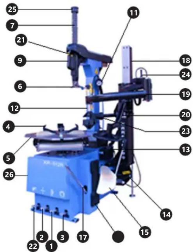
3.1. DEVICE DESCRIPTION

ATTENTION! This product's view can be found on the last pages of the operating instructions (pp. 64).
- Separator control pedal
- Jaws control pedal
- Turntable rotation control pedal
- Clamping jaws
- Turntable
- Mounting head
- Mounting arm
- Knob limiting the movement of mounting arm
- Swivel arm
- Locking lever
- Inflation gun with pressure gauge
- Column
- Accessories / grease container
- Separator arm
- Separator blade
- Stopper
- Tyre lever
- Three-tool support
- Tyre bead clamp
-
Circular roller
-
Locking switch
- Column control pedal
- Pressure roller
- Three-tool support control switch
- Security tip
- Machine body
Operation of control pedals:
- Press the pedal to start the tyre separator. After releasing the pedal, the separator returns to its starting position.
- Press the pedal to open the four jaws of the device. Press again to close the jaws.
- When the pedal is pressed, the turntable will rotate clockwise. When the pedal is released, the turntable will rotate counter-clockwise. 22 (only model MSW-TC-1100HA) – Pressing the pedal causes the column to tilt backwards. Pressing the pedal again causes the column to return to its initial position.
The compressed air gun trigger can be in 3 positions:
- trigger in its initial position (not pressed) – the air flow is closed
- trigger partially depressed – air is let out
- trigger pressed all the way – air is pumped in
3.2. PREPARING FOR USE
Unpacking
Use gloves when unpacking the machine. After unpacking, check that it is in good condition and that all parts have been delivered and are not damaged. If in doubt as to the efficiency and completeness of the machine, contact the manufacturer. The packaging and its components (nails, plastic bags, clamps, films, pieces of wood) should be kept (for transport or storage of the machine) in a safe place away from children.
APPLIANCE LOCATION
The following conditions should apply in the workplace:
| Ambient temperature [°C] (-20)-45 | |
| Humidity [%] 30-95 | |
| Maximum height above sea level [m] | 1000 |
Ensure good ventilation in the room in which the device is being used. There should be at least 10 cm distance between each side of the device and the wall or other objects. Keep the device away from hot surfaces. Operate the device on an even, stable, clean, fire-proof and dry surface and out of the reach of children and persons with mental disabilities. The machine should be positioned in such a way that at any time you can reach the mains plug and the valve that switches off the compressed air supply. Make sure that the air pressure and power supply requirements correspond to the data provided on the nameplate!
The device should be placed in such a way that the free space around is not smaller than in the drawing.
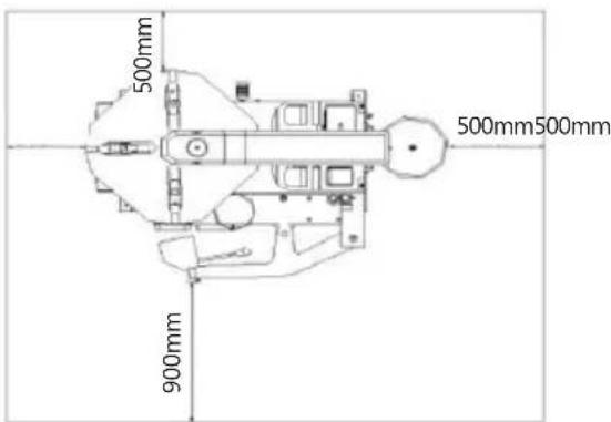
If the machine is placed outside the building, it must be roofed and adequately shielded from weather conditions.
ASSEMBLING THE APPLIANCE
MSW-TC-750
- Pull the locking lever [10] of the mounting arm.
- Extend the mounting arm [7] fully to the top.
- Lock the position of the mounting arm [7] using the locking lever [10].
- Remove the protective tip [25] of the mounting arm [7] using a suitable wrench.
- Slide the spring onto the mounting arm [7].
- Put the protective tip [25] on the upper part of the arm [7] and secure the connection using the appropriate wrench.
- Mount the column [12] with the mounting arm [7] on the machine body [26] using four bolts and nuts.
- Mount the movement limiting knob [8] in the horizontal part of the mounting arm [7].
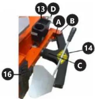
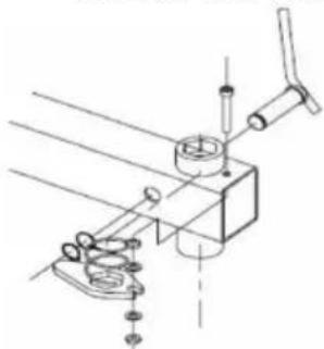
- Mount the separator arm [14] on the shank [B] found on the side of the machine body [26].
- Unscrew the nut from the piston rod [C] (in the drawing it is obscured by the separator arm) protruding from the side of the machine body [26].
- Put the separator arm [14] on the piston rod [C] and secure the connection with the nut.
- Install the small spring [A] between the separator arm [14] and the machine body [26].
- Install the accessories / lubricant container [13] on the right side of the machine body.
- Insert the tyre lever into the hole behind the stopper [16].
- Attach the blow gun hose [11] to the top connection of the compressed air unit of the machine [D].
- Connect the compressed air supply line to the side connection of the compressed air unit [D].
3.3. DEVICE USE
Machine operation is divided into four parts:
1) separating the tyre
2) removing the tyre
3) mounting the tyre
4) pumping the tyre
IMPORTANT: Before using the machine, deflate the tyre and remove all balance weights from the rim.
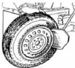
1) Separating the tyre
IMPORTANT: Exercise caution when using the separator. Anything within the range of the separator's arm is vulnerable to crushing.
a) Deflate the tyre before you start to separate it.
b) Fully close the turntable jaws by pressing the pedal (2).
c) Lean the wheel against the stopper found on the right side of the machine. Position the edge of the separator blade along the tyre bead, approximately 1 cm from the rim.
natural_image
Technical line drawing of a tire assembly with mounting bracket (no text or symbols)d) Press the pedal (1) to start the separator.
The separator arm presses on the tyre and separates it from the rim.
e) Release the pedal (1) so that the separator returns to its initial position.
f) Turn the tyre a little and repeat the tyre peeling process.
g) Repeat the above steps until the entyre tyre is detached from the rim.
h) Turn the tyre to the other side and repeat the peeling process.
2) Removing the tire
IMPORTANT: Before using the machine, deflate the tyre and remove all balance weights from the rim.
MSW-TC-1100HA
NOTE: When tilting the column, make sure that nobody is behind the machine.
a) Press the pedal (22) to tilt the column.
b) Position the wheel on the turntable jaws (in the case of asymmetrical rims, the narrower part of the rim should be up).
c) Tighten the wheel in the turntable jaws by pressing the pedal (2). In order to properly grip the wheel with the jaws, it must be positioned exactly in the middle of the turntable.
WARNING: Do not hold your hands under the wheel while clamping the turntable jaws.
Gripping the rim from the outside:
I. Press the pedal (2) and open the jaws.
II. Position the wheel on the jaws and press the pedal (3) all the way down to tighten the rim. The jaws will grip the wheel.
Gripping the rim from the inside:
I. Set the jaws in the closed position.
II. Position the wheel on the jaws and press the pedal (2). The jaws will part and grip the wheel.
d) Ensure that the rim is securely clamped by the jaws.
e) Apply a proper slip enhancer to the tyre bead as follows:
- Place the pressure roller on the side of the tyre and press the tyre lightly with it (push the switch (24) forward to lower the roller position). This will bend the bead away from the rim and lubricate the bead and the rim edge with a suitable slip enhancer.
II. Turn the rotary table by pressing the pedal (3) and at the same time lubricate with a brush soaked in the slip enhancer.
natural_image
Line drawing of a car tire with a hand cleaning the rim (no text or symbols)WARNING: Not lubricating the rim bead will cause serious damage to the tyre.
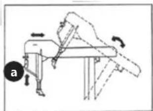
f) Press the pedal (22), the column will be restored to its initial position.
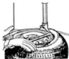
natural_image
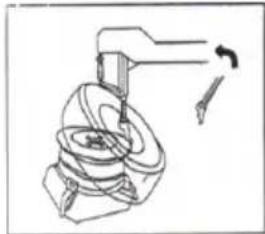
Diagram of a mechanical exercise setup with a table, arm, and directional arrows indicating motion (no text or symbols)g) Press the locking button (21) in the holder and lower the mounting arm until the mounting head rests against the rim edge.
h) Lock the mounting arm with the button (21) on the holder.
IMPORTANT: Keep a distance of approx. 1-2 mm vertically and approx. 3-5 mm horizontally between the mounting head and the rim edge.
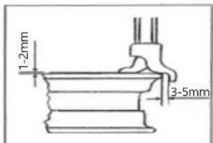
WARNING: Do not put your hands on the wheel when mounting it. When the mounting arm is being moved to its working position, the user's hand can be crushed between the rim and the mounting head.
WARNING: In order to avoid damage to the inner tube (if there is one in the tyre), when the mounting head and the tyre lever are being positioned, the inner tube valve should be moved away by 10 cm to the right of the mounting head.
i) Slide the tyre lever under the tyre bead. While holding the tyre lever against the recess in the mounting head, tilt the protruding part of the lever towards the rim.
natural_image
Illustration of a hand operating a circular device with pipes and a chimney (no text or symbols visible)j) Turn the table clockwise by pressing the pedal (3) until the tyre is completely separated from the rim. If the tyre removal process is stopped by an interlock or slowed down by large resistance, stop the table rotation (stop pressing the pedal 3) and temporarily reverse the table rotation by releasing the pedal (3). Release the interlock and continue removing the tyre.

natural_image
Line drawing of a bowl with internal patterns and a handle (no text or symbols)WARNING: Keep your hands and other parts of the body as far as possible from the mounting arm when the table is turning.
k) Remove the tube (if any) from the tyre. To facilitate this, tilt the column by pressing the pedal (22).
I) To facilitate removal of the second tyre bead from the rim, you can use the circular roller.
I. Set the circular roller so that it touches the bottom side of the tyre and half of the roller is under the tyre.
II. Use the switch (24) and pedal (3) to lift the tyre to the upper edge of the rim.
m) Remove the other side of the tyre in the same way without changing the position of the rim. Slide the tyre lever under the tyre bead. While holding the lever against the recess in the mounting head, tilt the protruding part of the lever towards the rim.
n) Turn the table clockwise by pressing the pedal (3) until the tyre is completely separated from the rim.
o) Tilt the column by pressing the pedal (22) and remove the tyre.
MSW-TC-750a)
a) Unlock the position of the mounting arm by pulling the lever (10) and raise the mounting arm.
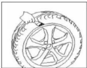
b) Apply a proper slip enhancer to the tyre bead.
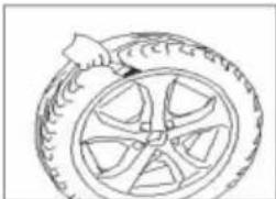
natural_image
Line drawing of a car tire with a hand adjusting the wheel (no text or symbols)WARNING: Not lubricating the rim bead will cause serious damage to the tyre.
c) Position the wheel on the turntable jaws (in the case of asymmetrical rims, the narrower part of the rim should be up).
d) Tighten the wheel in the turntable jaws by pressing the pedal (2). In order to properly grip the wheel with the jaws, it must be positioned exactly in the middle of the turntable.
WARNING: Do not hold your hands under the wheel when closing the turntable jaws.
Gripping the rim from the outside:
I. Press the pedal (2) and open the jaws.
II. Position the wheel on the jaws and press the pedal (3) all the way down to tighten the rim. The jaws will grip the wheel.
Gripping the rim from the inside:
- Set the jaws in the closed position.
II. Position the wheel on the jaws and press the pedal (2). The jaws will part and grip the wheel.
e) Make sure that the rim is securely clamped in the jaws.
f) Lower the mounting arm until the mounting head rests on the rim edge.
g) Lock the mounting arm using the lever (10).
IMPORTANT: Keep the distance of approx. 2 mm between the mounting head and the rim edge.
WARNING: Do not put your hands on the wheel when mounting it. When the mounting arm is being moved to its working position, the user's hand can be crushed between the rim and the mounting head.
WARNING: In order to avoid damage to the inner tube (if there is one in the tyre), when the mounting head and the tyre lever are being positioned, the inner tube valve should be moved away by 10 cm to the right of the mounting head.
h) Slide the tyre lever under the tyre bead. While holding the lever against the recess in the mounting head, tilt the protruding part of the lever towards the rim.
natural_image
Line drawing of a mechanical component with a cylindrical shaft and textured base (no text or symbols)i) Turn the table clockwise by pressing the pedal (3) until the tyre is completely separated from the rim. If the tyre removal process is stopped by an interlock or slowed down by large resistance, stop the table rotation (stop pressing the pedal 3) and temporarily reverse the table rotation by releasing the pedal (3). Release the interlock and continue removing the tyre.
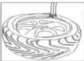
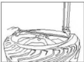
natural_image
Line drawing of a circular object with internal geometric patterns and a handle (no text or symbols)WARNING: Keep your hands and other parts of the body as far as possible from the mounting arm when the table is turning.
j) Remove the tube if there is one in the tyre. Lift the mounting arm by pulling the locking lever (10) to facilitate removal of the inner tube.
k) The other side of the tyre should be peeled off in the same way without changing the rim position.
Slide the tyre lever under the tyre bead. While holding the lever against the recess in the mounting head, tilt the protruding part of the lever towards the rim.
I) Turn the table clockwise by pressing the pedal (3) until the tyre is completely separated from the rim.
m) Pull the lever (10) to move the mounting arm upwards, then remove the tyre.
3) Mounting the tyre
WARNING: An unsuitable tyre or a tyre in poor condition can burst when inflated. Before mounting the tyre, check the following:
• The tyre and presure hose are not damaged. A damaged tyre must never be mounted.
- The rim is without dents and is not bent. Special attention should be paid to aluminum wheels, which may be cracked on the inside and the defect may not be visible to the naked eye. Rims that are bent, dented or with hidden material defects can be potentially dangerous when the tyre is being inflated.
- The tyre and rim diameters are the same. Do not mount tyres on rims unless it is clear without doubt that the diameters are the same.
a) Lubricate the tyre beads with a suitable agent to avoid damage and to facilitate assembly.
b) Place the rim in the center of the turntable, lightly press the rim and press the pedal (2) so that the clamping jaws will grip the rim.
c) Position the tyre on the rim so that the mounting head can be placed against the rim.
d) (This step applies only to the model MSW-TC-1100HA). Put the column in an upright position.
natural_image
Mechanical assembly diagram showing a clamping mechanism with a tool and rotating component (no text or labels)e) Lower the mounting arm until the mounting head rests against the edge of the rim (if the arm is locked, it must be unlocked first using the locking lever (10) for the MSW-TC-750 model or the button on the handle (21) for the MSW - model TC-1100h).
f) Lock the mounting arm with the lever (10) for the MSW-TC-750 model or the button on the handle (21) for the MSW-model TC-1100h). The mounting head will be locked in a vertical position. IMPORTANT: Keep a distance of approx. 1-2 mm vertically and approx. 3-5 mm horizontally between the mounting head and the rim edge.
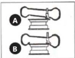
g) Position the tyre so that its bead passes over the head (A) from the back of the mounting head and under the head (B) from the front of the mounting head.
natural_image
Two mechanical clamps labeled A and B, showing different mounting configurations (no text or symbols present)h) Press the tyre towards the rim and simultaneously press the pedal (3) to rotate the turntable clockwise. Continue this operation until the entire bead has passed the edge of the rim. If the tyre requires an inner tube, insert it.
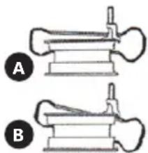
i) Position the tyre so that its upper bead passes over the head (A) from the back of the mounting head and under the head (B) from the front of the mounting head.
natural_image
Two mechanical components labeled A and B, showing different assembly forms (no text or symbols present)j) Press the tyre towards the rim and simultaneously press the pedal (3) to rotate the turntable clockwise. Continue this operation until the entire bead has passed the rim edge. It is recommended to take extra care to slow down the tyre-mounting process when only 10-15 cm of unmounted tyre remain.
• (For the MSW-TC-1100HA model)
In order to facilitate the work, it is possible to use a tyre bead presser and a pressure roller.
1. Position the pressure roller on the side of the tyre approximately 10 cm to the right of the mounting head.
II. Position the bead presser on the side of the tyre approximately 10 cm to the right of the pressure roller.
III. Lower the pressure roller and the bead presser so as to put a small pressure on the tyre (when using the bead presser, it is not recommended to touch the tyre when the turntable is rotating).
IV. Rotate the turntable by pressing the pedal (3)
NOTE: Tyre mounting and demounting is always carried out when the table is rotating in a clockwise direction. The anti-clockwise movement is used only to correct operator errors.
4) Inflating the tyre

ATTENTION! Inflating tyres is a dangerous operation! Please follow the instructions given.
Pay special attention when inflating tyres. The machine is not designed to provide adequate protection to the user or persons in the vicinity of the machine in case of tyre explosion.
WARNING: A tyre explosion can cause serious injury, even death. Before inflating the tyre, make sure that the diameter of the tyre and rim are the same, check the technical condition of the tyre and check if the pressure hoses are connected properly.
natural_image
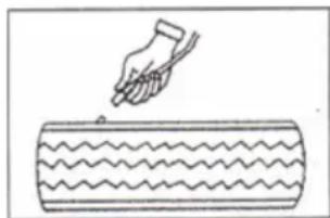
Simple line drawing of a hand pressing down on a wavy object (no text or symbols)a) Connect the compressed air line to the wheel valve (remove the valve stem first).
b) Start pumping with the compressed air gun (press the trigger all the way down).
c) After the bead is pushed out, remove the compressed air hose, insert the stem into the tyre valve and proceed to inflate the tyre as required.
d) Connect the compressed air line to the valve in the wheel and start pumping. Make frequent breaks to check the pressure inside the tyre. The maximum inflating pressure must not exceed 3 bar for the model MSW-TC-1100HA or 3.5 bar for the model MSW-TC-750.
If the pressure inside the tyre is to reach a value close to the maximum values for the given model of tyre changer, it is recommended to remove the tyre from the machine and pump it behind a suitable guard that will protect the user and the persons around from possible explosion.
NOTE: When inflating tyres keep your hands and other parts of the body as far as possible from the machine.
3.4. TRANSPORTING THE MACHINE
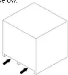
The machine must be transported in its original packaging and only in the position indicated on the packaging. The packaged machine can be transported only with a forklift having the permissible load at least equal to the weight of the packaged machine. The fork should be placed as shown below.
natural_image
Simple 3D diagram of a cube with two arrows pointing to its side (no text or symbols)Moving the machine over short distances
- The machine can be moved over short distances only with a forklift.
- Before moving the machine, disconnect it from the power and compressed air supply.
a) Lift and slightly raise the machine on one side with a sufficiently strong lever.
b) Slide the fork under the machine.
c) Lift and move the machine to a new location. The transport and storage temperature should be in the range of -20 to 55°C.
Scrapping
- It is recommended to break all power cords to make them inoperable.
- Dispose of the non-metallic materials in accordance with regulations.
- Drain the oil and dispose of it in accordance with regulations.
- Deliver the rest of the machine to an authorized metal waste collection point.
3.5. HAZARDS IN THE COURSE OF USING THE DEVICE The hazards that can occur during use of the machine are mechanical hazards. The mechanical hazard occurs in situations in which injuries can result from mechanical impact of various elements, e.g. machine parts, tools, etc. on people. The basic mechanical hazards include squeezing, crushing, cutting, pulling in or catching; impact; puncture; abrasion; as well as slipping and stumbling.
These hazards can occur both during normal machine operation and as a result of irregularities in machine operation. These irregularities might result in machine failure. The mechanical hazards can result from: moving machines, transported loads, moving elements, sharp/rough elements, dropping elements/loads, slippery uneven surfaces, limited space, location of the work station in relation to the ground.
3.6. CLEANING AND MAINTENANCE
a) Before each cleaning, adjustment, exchange of accessories and when the device is not in use, disconnect the mains plug and the compressed air supply line, equalize the pressure in the cylinders with atmospheric pressure and completely cool the device.
b) Use only non-corrosive cleaners to clean the surface.
c) After cleaning the device, all parts should be dried completely before using it again.
d) Store the unit in a dry, cool place, free from moisture and direct exposure to sunlight.
e) Before putting the machine into storage, lubricate all coupled moving parts, empty the oil / liquid container and cover the machine with a plastic tarp to prevent dust settling on it.
f) Never spray the device with water.
g) Do not allow water to get inside the device through vents in the housing of the device.
h) Clean the vents with a brush and compressed air.
i) The device must be regularly inspected to check its technical efficiency and spot any damage.
j) Use a soft cloth for cleaning.
k) Movable parts should be regularly lubricated depending on how often they are used. It is recommended to do this once a week.
I) Regularly check and correct the drive belt tension.
m) Regularly check the connections of all parts and tighten the loose nuts and bolts.
n) Regularly check and remove sediment, contamination and water from the compressed air unit of the machine.
Inspections and periodic control
Before being used, the new or repaired machine must be checked by qualified technical personnel who have knowledge and experience within the scope of operation and maintenance of this type of machine. The machine must be checked regularly by means of visual control of the machine's condition, before, during and after use. The check must be performed by the machine's operators. Any irregularities in machine operation as well as any damage must be reported to the proper technical personnel. Do not use the machine if damage or any irregularities in its operation were found.
IMPORTANT: Before each inspection, disconnect the machine from the power and compressed air supply. After disconnecting the power supply, use the separator 3-4 times to get rid of the pressure in the machine's pneumatic system.
Machine inspection every 30 days:
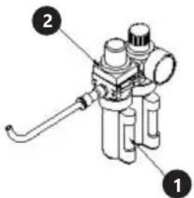
- Check the oil level in the lubricating tank. The recommended oil is SAE30.
- Check that there is oil in the tank (1). One drop of oil should be added every 3-4 clicks of the separator control pedal. If it is not, adjust with the screw (2) as shown in the drawing below.
- Tighten the jaw screws and screws under the turntable.
- If the turntable does not work, the drive belt may be too loose. Adjust the drive belt.
- Adjust the locking lever screw [10] (applies to MSW-TC-750) to allow the mounting arm to be locked
natural_image
Technical line drawing of a mechanical assembly with no visible text or symbols- If the clamping jaws or the separator move too slowly, clean or replace the suppressor.
DANE TECHNICZNE
natural_image
Technical line drawing of a car tire mounted on a vehicle (no text or symbols)natural_image
Line drawing of a hand cleaning a car tire (no text or symbols)natural_image
Diagram of a mechanical or ergonomic device with directional arrows indicating movement (no text or symbols)natural_image
Illustration of hands operating a mechanical device with a cylindrical component (no text or symbols visible)natural_image
Line drawing of a circular object with internal patterns and a handle (no text or symbols)natural_image
Line drawing of a car tire with a hand holding the rim (no text or symbols)natural_image
Line drawing of a car tire with handle and wheel (no text or symbols)natural_image
Line drawing of a car wheel with visible blades and hub (no text or symbols)natural_image
Mechanical assembly diagram showing a rotating component with arrows indicating motion (no text or symbols)natural_image
Diagram of two mechanical components labeled A and B, showing assembly or assembly steps without any text or symbols.natural_image
Two mechanical components labeled A and B, showing different assembly forms (no text or symbols present)natural_image
Simple line drawing of a hand pressing down on a cylindrical object with wavy lines (no text or symbols)natural_image
Simple line drawing of a 3D cube with two black arrows pointing to its side (no text or symbols)natural_image
Technical line drawing of a mechanical assembly with no visible text or symbolsnatural_image
Technical line drawing of a car tire mounted on an industrial vehicle (no text or symbols)natural_image
Line drawing of a car tire with a hand holding the tire (no text or symbols)natural_image
Diagram of a mechanical device with directional arrows indicating motion (no text or symbols)natural_image
Illustration of a hand operating a mechanical device with a cylindrical component (no text or symbols visible)natural_image
Line drawing of a decorative bowl with floral patterns and a handle (no text or symbols)natural_image
Line drawing of a car tire with a handle, no text or symbols presentnatural_image
Line drawing of a mechanical component with a handle and base, no text or symbols presentnatural_image
Line drawing of a mechanical component with concentric grooves and a central hub (no text or symbols)natural_image
Mechanical assembly diagram showing a rotating component with a tool and directional arrow (no text or labels)natural_image
Diagram of two mechanical components labeled A and B, showing assembly or assembly steps without any text or symbols.natural_image
Two diagrams of a mechanical or anatomical structure labeled A and B, showing different views (no text or symbols present)natural_image
Simple line drawing of a hand using a tool to press or mark a wavy object on a rectangular surface (no text or symbols)natural_image
Simple line drawing of a 3D cube with two black arrows pointing downward on its side (no text or symbols)natural_image
Technical line drawing of a mechanical assembly with no visible text or symbolsnatural_image
Technical line drawing of a tire mounted on a vehicle (no text or symbols)natural_image
Line drawing of a car tire with a hand holding the tire (no text or symbols)natural_image
Diagram of a mechanical device with directional arrows indicating motion (no text or symbols)natural_image
Illustration of a hand operating a circular mechanical device with pipes and a base (no text or symbols visible)natural_image
Line drawing of a circular object with internal patterns and a handle (no text or symbols)natural_image
Line drawing of a car tire with a hand holding the wheel (no text or symbols)natural_image
Line drawing of a mechanical component with a curved base and lever (no text or symbols)natural_image
Line drawing of a car wheel with visible blades and hub (no text or symbols)natural_image
Mechanical assembly diagram showing a clamping mechanism with a tool and arrow indicating motion (no text or symbols)natural_image
Diagram of two mechanical components labeled A and B, showing assembly or assembly steps without any text or symbols.natural_image
Two mechanical components labeled A and B, showing different assembly forms (no text or symbols present)natural_image
Simple line drawing of a hand using a tool to press or mark a wavy object on a cylindrical surface (no text or symbols)natural_image
Simple line drawing of a 3D cube with two arrows pointing to its side (no text or symbols)natural_image
Technical line drawing of a mechanical assembly with no visible text or symbolsnatural_image
Technical line drawing of a car tire mounted on a vehicle (no text or symbols)natural_image
Line drawing of a hand cleaning a car tire (no text or symbols)natural_image
Diagram of a mechanical or ergonomic device with directional arrows indicating movement (no text or symbols)natural_image
Illustration of a hand operating a mechanical device with a cylindrical component (no text or symbols visible)natural_image
Line drawing of a bowl with decorative patterns and a handle (no text or symbols)natural_image
Line drawing of a car tire with a hand holding the tire (no text or symbols)natural_image
Line drawing of a mechanical component with a tool inserted, no visible text or symbolsnatural_image
Line drawing of a mechanical component with concentric grooves and a central hub (no text or symbols)natural_image
Diagram of a mechanical device with a rotating shaft and housing (no text or symbols)natural_image
Diagram of two mechanical components labeled A and B, showing different assembly configurations (no text or symbols present)natural_image
Two mechanical components labeled A and B, showing different assembly forms (no text or symbols present)natural_image
Simple line drawing of a hand using a tool to press or write on a textured cylindrical object (no text or symbols)natural_image
Simple line drawing of a 3D cube with two arrows pointing to its side (no text or symbols)natural_image
Technical line drawing of a mechanical assembly with no visible text or symbolsnatural_image
Technical line drawing of a car tire mounted on a vehicle (no text or symbols)natural_image
Line drawing of a car tire with a hand cleaning the wheel (no text or symbols)natural_image
Diagram of a mechanical device with directional arrows indicating movement (no text or symbols)natural_image
Illustration of a hand operating a mechanical device with a cylindrical component (no text or symbols visible)natural_image
Line drawing of a circular object with internal patterns and a rod inserted (no text or symbols)natural_image
Line drawing of a car tire with a hand holding the rim (no text or symbols)natural_image
Line drawing of a mechanical component with a handle and base, no text or symbols presentnatural_image
Line drawing of a mechanical component with concentric grooves and a central shaft (no text or symbols)natural_image
Mechanical assembly diagram showing a tool interacting with a mechanical component (no text or symbols visible)natural_image
Diagram of two mechanical components labeled A and B, showing assembly or assembly steps without any text or symbols.natural_image
Two mechanical components labeled A and B, showing different assembly forms (no text or symbols present)natural_image
Simple line drawing of a hand using a tool to press or mark a wavy object on a rectangular surface (no text or symbols)natural_image
Simple line drawing of a 3D cube with two arrows pointing to its side (no text or symbols)natural_image
Mechanical assembly diagram showing a clamp and mounting bracket with no visible text or symbolsMSW-TC-1100HA
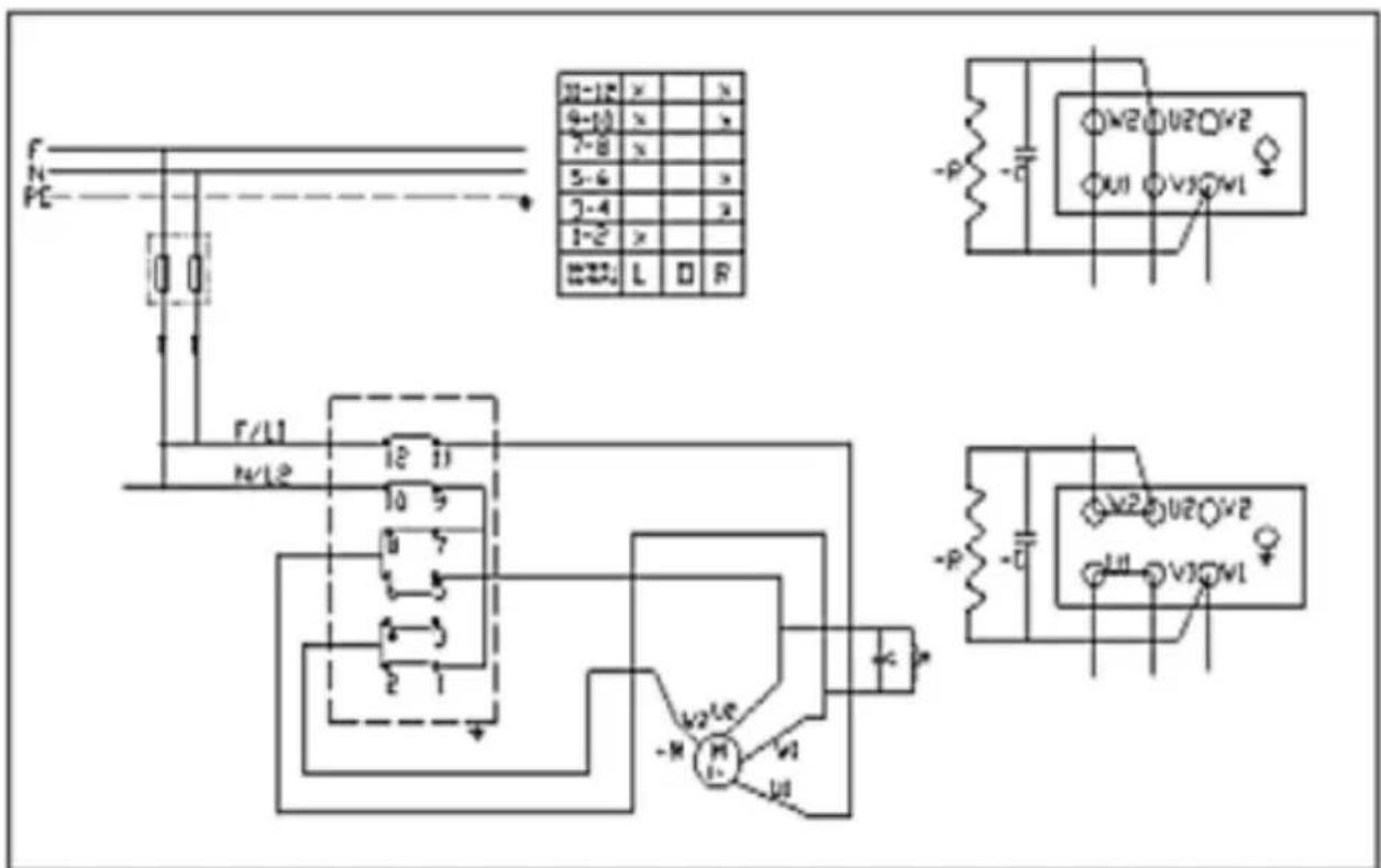
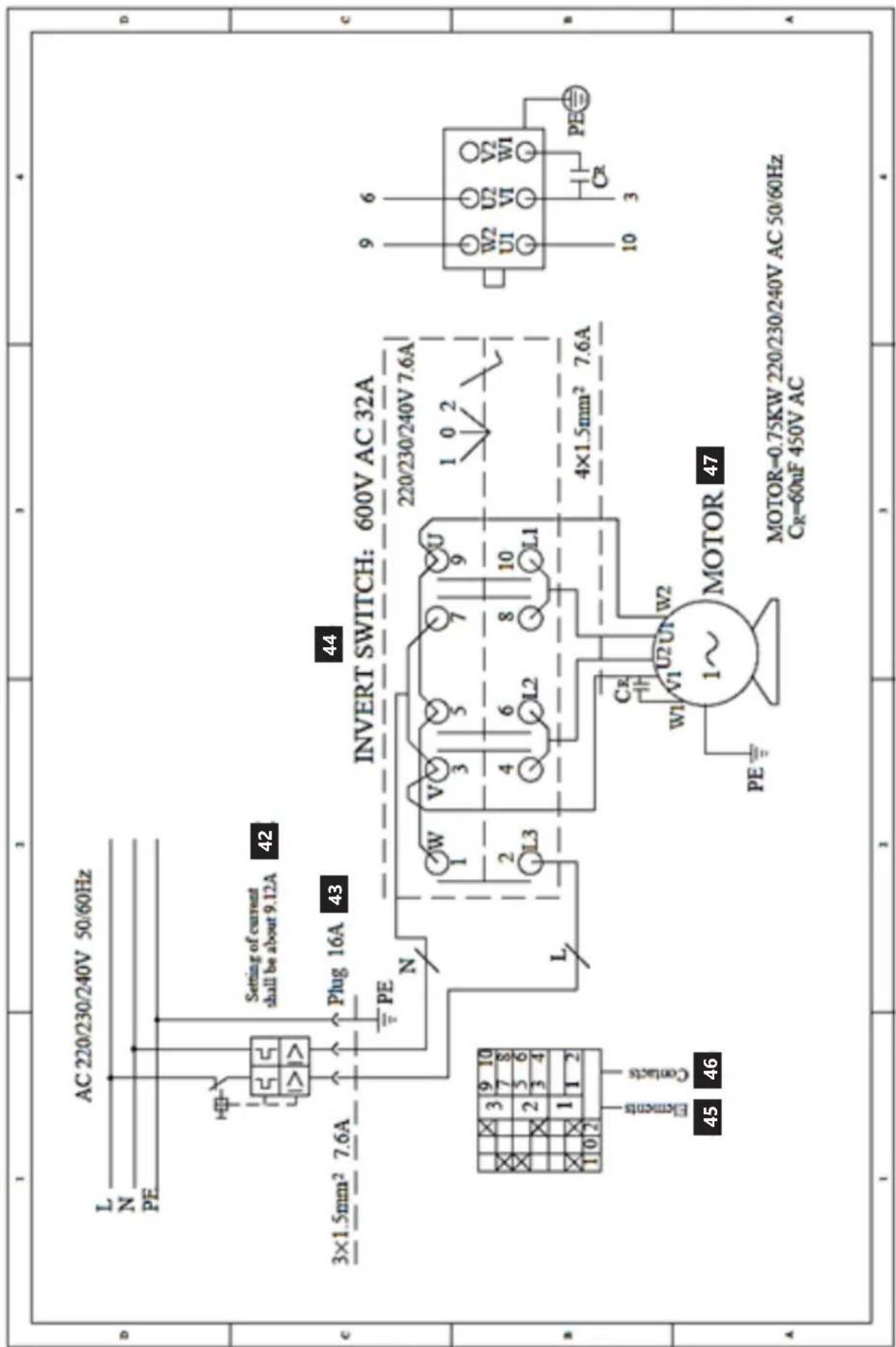
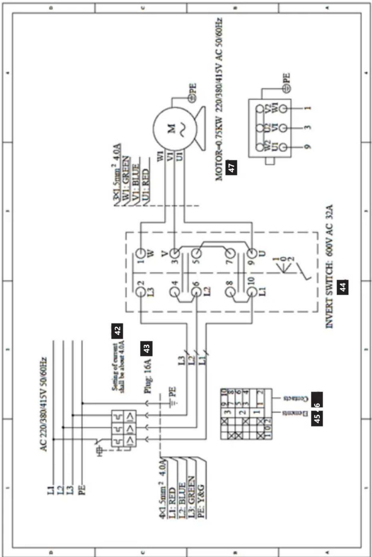
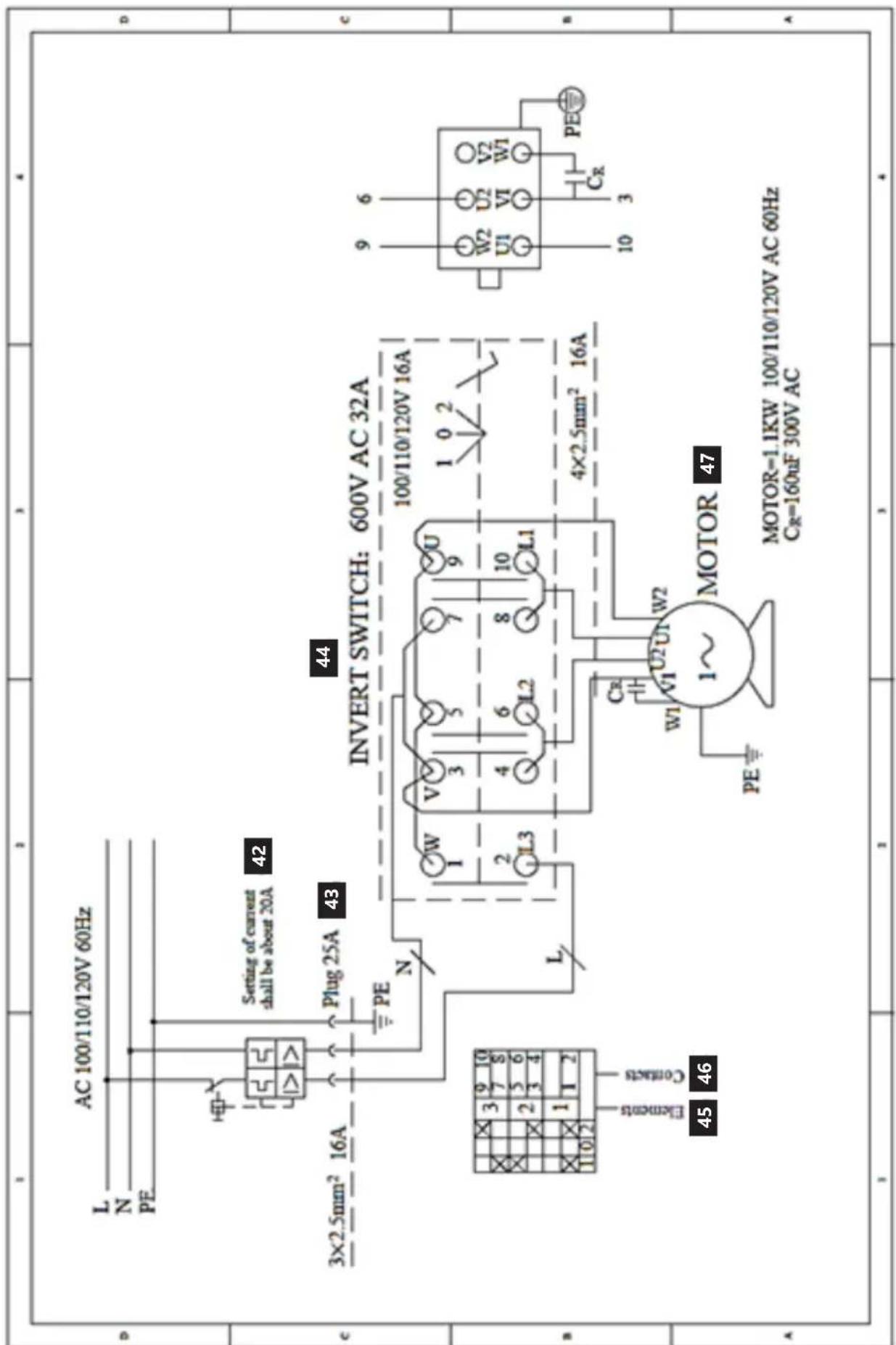
ELEKTRISCHES SCHEMA / WARNING DIAGRAM / SCHEMAT ELEKTRYCZNY / ELEKTRICKÉ SCHÉMA SCHÉMA ÉLECTRIQUE / SCHEMA ELETTRICO / ESQUEMA ELÉCTRICO
MSW-TC-750


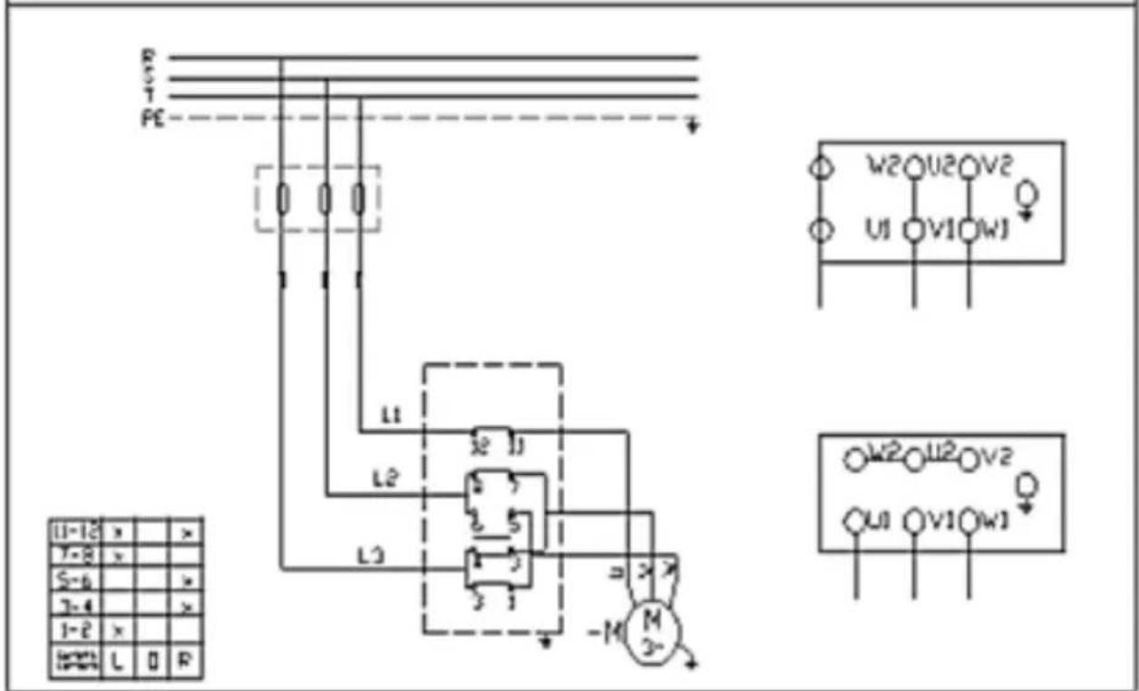
MSW-TC-1100HA
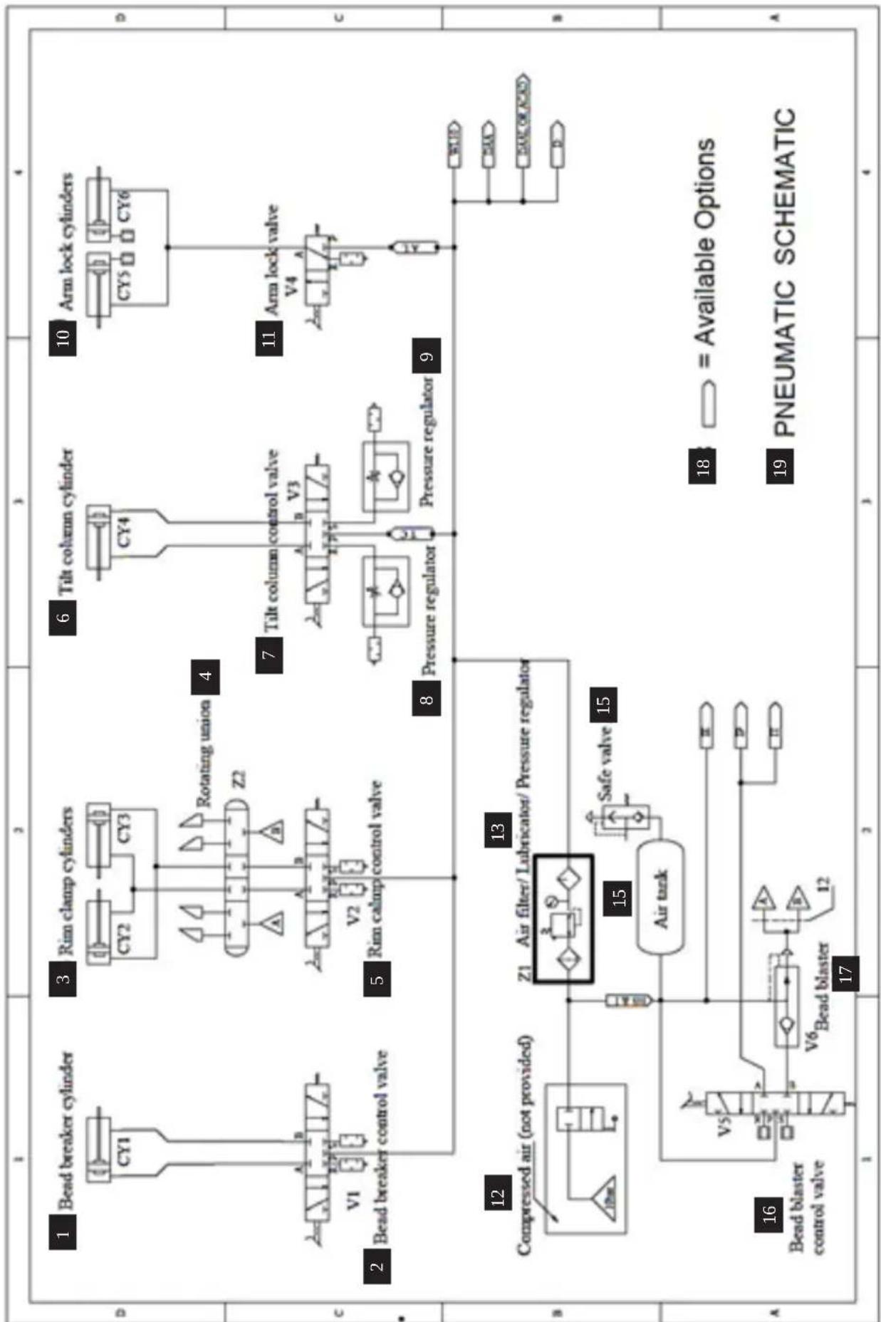
flowchart
graph TD
    A["1"] --> B["11"]
    B --> C["12"]
    C --> D["13"]
    D --> E["14"]
    E --> F["15"]
    F --> G["16"]

    subgraph Section A
        H["Bead breaker cylinder"] --> I["CY1"]
        J["Bead breaker control valve"] --> K["V1"]
        L["Rim clamp cylinders"] --> M["CY2"]
        N["Rim calmp control valve"] --> O["V2"]
    end

    subgraph Section B
        P["Tilt column cylinder"] --> Q["CY4"]
        R["Tilt column control valve"] --> S["V3"]
        T["Pressure regulator"] --> U["Pressure regulator"]
        V["Compressed air (not provided)"] --> W["Z1"]
        X["Bead blaster control valve"] --> Y["V5"]
        Z["Bead blaster"] --> AA["V6"]
    end

    subgraph Section C
        AB["Arm lock cylinders"] --> AC["CY5"]
        AD["Arm lock valve"] --> AE["V4"]
    end

    subgraph Section D
        AF["= Available Options"] --> AG["PNEUMATIC SCHEMAIC"]
    end
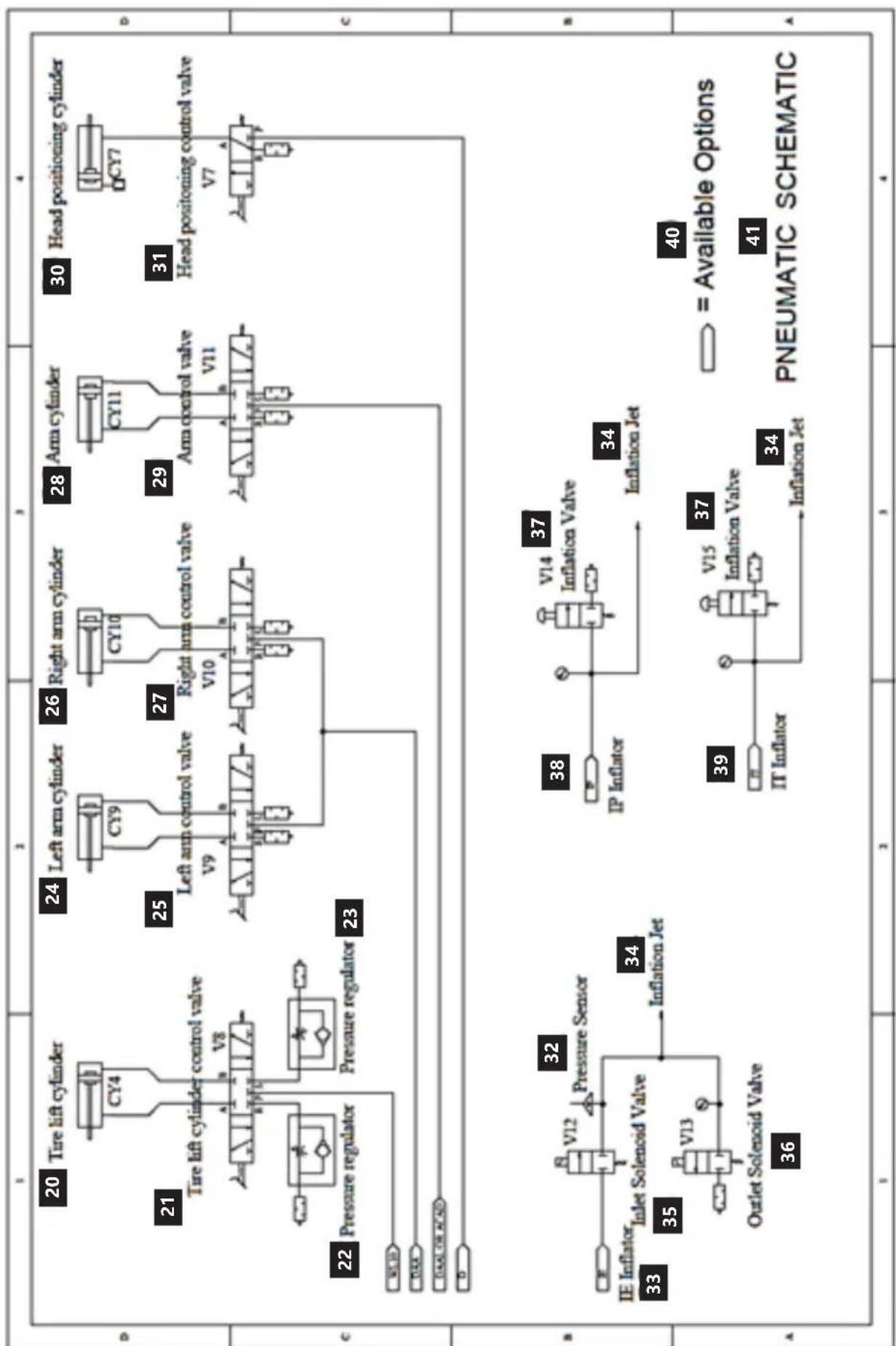
flowchart
graph TD
    A["20 Tire lift cylinder"] --> B["CY4"]
    C["21 Tire lift cylinder control valve"] --> D["V8"]
    E["22 Pressure regulator"] --> F["Pressure regulator"]
    G["23"] --> H["24 Left arm cylinder"]
    I["24"] --> J["CY9"]
    K["25 Left arm control valve"] --> L["V9"]
    M["26 Right arm cylinder"] --> N["CY10"]
    O["27 Right arm control valve"] --> P["V10"]
    Q["28 Arm cylinder"] --> R["CY11"]
    S["29 Arm control valve"] --> T["V11"]
    U["30 Head positioning cylinder"] --> V["CY7"]
    W["31 Head positioning control valve"] --> X["V7"]
    Y["32 Pressure Sensor"] --> Z["V12"]
    AA["33 IE Inflator"] --> AB["V13"]
    AC["34 Inflation Jet"] --> AD["V14 Inflation Valve"]
    AE["35 Outlet Solenoid Valve"] --> AF["V15 Inflation Valve"]
    AG["36 Inflation Jet"] --> AH["V14 Inflation Valve"]
    AI["38 IP Inflator"] --> AJ["V14 Inflation Valve"]
    AK["39 IT Inflator"] --> AL["V15 Inflation Valve"]
    AM["40 = Available Options"] --> AN["PNEUMATIC SCHEMAIC"]
| Nr. | DE EN PL CZ FR IT ES | ||||||
| 1 | Abdrückeran-trieb | Bead breaker cylinder | Siłownik odrywacza | Servomotor odráżeče | Vérin du détalonneur | Attuatore dello stallonatore | Cilindro del separador |
| 2 | Steuerventil für den Abdrücker | Bead breaker control valve | Zawór sterujący odrywaczem | Rídící ventil odráżeče | Vanne de commande du détalonneur | Valvola di controllo dello stallonatore | Válvula de control del separador |
| 3 | Klemmbacken-antrieb | Rim Clamp cylinders | Siłowniki szczęk zaciskowych | Servomotory upínacích čelisti | Vérin des mâchoires | Attuatori delle griffe di bloccaggio | Cilindros de las mordazas de sujeción |
| 4 | Schwenkverbinder | Rotating union | Złącze obrotowe | Otočný konektor | Connecteur pivotant | Connettore girevole | Conector giratorio |
| 5 | Steuerventil für die Klemmbacken | Rim clamp control valve | Zawór sterujący szczękami zaciskowymi | Rídící ventil upínacích čelisti | Vanne de commande des mâchoires de serrage | Valvola di controllo delle griffe di bloccaggio | Válvula de control de las mordazas de sujeción |
| 6 | Kippsäulenan-trieb | Tilt column cylinder | Siłownik kolumny przechylnej | Servomotor naklápěciho sloupu | Vérin de la colonne inclinable | Attuatore della colonna | Cilindro del pilar inclinable |
| 7 | Steuerventil für die Kippsäule | Tilt column control valve | Zawór sterujący kolumny przechylnej | Rídící ventil naklápěciho sloupu | Vanne de commande de la colonne inclinable | Valvola di controllo della colonna | Válvula de control del pilar inclinable |
| 8 | Druckregler Pressure regulator | Regulator ciśnienia | Regulátor tlaku | Régulateur de pression | Regolatore di pressione | Regulador de presión | |
| 9 | Druckregler Pressure regulator | Regulator ciśnienia | Regulátor tlaku | Régulateur de pression | Regolatore di pressione | Regulador de presión | |
| 10 | Antrieb der Armverriege-lung | Arm lock cylinders | Siłownikiblokady ramienia | Servomotory blokády ramene | Vérin de blocage du bras | Cilindri di bloccaggio del braccio | Cilindros de bloqueo de brazo |
| 11 | Armverriege-lungsventil | Arm lock valve | Zawór blokady ramienia | Ventil blokády ramene | Vanne de blocage du bras | Valvola di blocco del braccio | Válvula de bloqueo del brazo |
| 12 | Druckluft (nicht mitgeliefert) | Compressed air (not provided) | Sprężone powietrze (nie zapewniane) | Stlačený vzduch (není součástí dodávky) | Air comprimé (non fourni) | Aria compressa (non fornita) | Aire comprimido (no incluido) |
| 13 | Luftfilter/Öler/Druckregler | Air filter/Lubrycator/Pressure regulator | Filtr powietrza/Smarownica/Regulator ciśnienia | Filtr vzduchu/Maznička/Regulátor tlaku | Filtre à air/Graisseur/Régulateur de pression | Filtro aria/Lubrificatore/Regolatore di pressione | Filtro de aire/Engrasadora/Regulador de presión |
| 14 | Sicherheits-ventil | Safe valve Zawór | bezpieczeństwa | Bezpečnostní ventil | Vanne de sécurité | Valvola di sicurezza | Válvula de seguridad |
| 15 | Luftbehälter Air tank Zbiornik | powietrza | Vzduchová nádrž | Réservoir d'air Serbatoio dell'aria | Tanque de aire | ||
| 16 | Steuerventil für den Inflator für die Explosions-pumpe | Bead blaster control valve | Zawór sterujący inflatora do uderzeniowego pompowania | Rídící ventil inflátora pro nárazové huštění | Vanne de commande du compresseur à air pour gonflage à choc | Valvola di controllo del gonfiatore per il pompaggio d'urto | Válvula de control del inflador de bombeo |
| 17 | Inflator für die Explosions-pumpe | Bead blaster Inflator do uderzeniowego pompowania | Inflátor pro nárazové huštění | Compresseur pour gonflage à choc | Gonfiatore per il pompaggio d'urto | Inflador de bombeo | |
| 18 | Verfügbare Optionen | Available Options | Dostępne opcje | Dostupné możnosti | Options disponibles | Opzioni disponibili | Opciones disponibles |
| 19 | PNEUMATI-SCHES SCHEMA | PNEUMATIC SCHEMATIC | SCHEMAT PNEUMATYCZY | PNEUMATICKÉ SCHÉMA | SCHÉMA PNEUMA-TIQUE | SCHEMA PNEUMA-TICO | ESQUEMA NEUMÁTICO |
| 20 | Reifenhieban-trieb | Tire lift cylinder | Siłownik podnoszący oponę | Servomotor zvedající pneumatiku | Vérin de levage du pneu | Cilindro per sollevamento pneumatici | Cilindro de elevación |
| 21 | Steuerventil mit Reifenhieb-antrieb | Tire lift cylinder control valve | Zawór sterujący | Ridící ventil servomotoru zvedající pneumatiku | Vanne de commande vérin de levage du pneu | Valvola di controllo del cilindro per sollevamento pneumatici | Válvula de control del cilindro que eleva el neumático |
| 22 | Druckregler Pressure regulator | Regulator ciśnienia | Regulator tlaku | Régulateur de pression | Regolatore di pressione | Regulador de presión | |
| 23 | Druckregler Pressure regulator | Regulator ciśnienia | Regulator tlaku | Régulateur de pression | Regolatore di pressione | Regulador de presión | |
| 24 | Antrieb des linken Arms | Left arm cylinder | Siłownik ramienia lewego | Servomotor levého ramene | Vérin du bras gauche | Attuatore del braccio sinistro | Cilindro del brazo izquierdo |
| 25 | Steuerventil für den linken Armantrieb | Left arm control valve | Zawór sterujący siłownikiem ramienia lewego | Ridící ventil servomotoru levého ramene | Vanne de commande du vérin du bras gauche | Valvola di controllo dell'attuatore del braccio sinistro | Válvula de control del cilindro del brazo izquierdo |
| 26 | Antrieb des rechten Arms | Right arm cylinder | Siłownik ramienia prawego | Servomotor pravého ramene | Vérin du bras droit | Attuatore del braccio destro | Cilindro del brazo derecho |
| 27 | Steuerventil für den rechten Armantrieb | Right arm control valve | Zawór sterujący siłownikiem ramienia prawego | Ridící ventil servomotoru pravého ramene | Vanne de commande du vérin du bras droit | Valvola di controllo dell'attuatore del braccio destro | Válvula de control del cilindro del brazo derecho |
| 28 | Armantrieb Arm cylinder Siłownik | Ramienia | Servomotor ramene | Vérin du bras | Attuatore del braccio | Cilindro del brazo | |
| 29 | Steuerventil des Arms | Arm control valve | Zawór sterujący ramienia | Ridící ventil ramena | Vanne de commande du bras | Valvola di controllo dell'attuatore del braccio | Válvula de control del brazo |
| 30 | Montagekopf-antrieb | Head positioning cylinder | Siłownik pozycjonujący głowicę | Servomotor přemístující hlavici | Vérin positionnant la tête | Attuatore di posiziona-mento della testa | Cilindro que posiciona el cabezal |
| 31 | Steuerventil für den Montage-kopfantrieb | Head positioning control valve | Zawór sterujący siłownikiem pozycjonującym głowicę | Ridící ventil servomotoru přemístující hlavici | Vanne de commande du vérin positionnant la tête | Valvola di controllo dell'attuatore di posiziona-mento della testa | Válvula de control del cilindro que posiciona el cabezal |
| 32 | Drucksensor Pressure Sensor | Czujnik ciśnienia | Snímac tlaku Capteur de pression | Sensore di pressione | Sensor de presión | ||
| 33 | IE Inflator | IE Inflator | IE Inflator | IE Inflator | IE Compres-seur | Gonfiatore IE Inflador IE | |
| 34 | Inflatordüse | Inflation Jet | Dysza inflatora | Tryska inflátora | Buse du compresseur | Ugello del gonfiatore | Boquilla del inflador |
| 35 | Einlass-Magnet-ventil | Inlet Solenoid Valve | Wlotowy zawór elektromagne-tyczny | Vstupní elektromagne-tický ventil | Électrovanne d'entrée | Elettrovalvo-la di ingresso | Válvula elec-tromagnética de entrada |
| 36 | Auslass-Mag-netventil | Outlet Solenoid Valve | Wylotowy zawór elektromagne-tyczny | Výstupní elek-tromagnetický ventil | Électrovanne de sortie | Elettrovalvo-la di uscita | Válvula elec-tromagnética de salida |
| 37 | Inflatorventil Inflation | Valve | Zawór inflacyjny Inflační ventil Embout de | Valvola di gonfiaggio | Válvula de inflado | ||
| 38 | IP Inflator IP Inflator | IP Inflator IP Inflátor IP | gonflage | Gonfiatore IP Inflador IP | |||
| 39 | IT Inflator IT Inflator | IT Inflator | IT Inflátor IT | compresseur | Gonfiatore IT Inflador IT | ||
| 40 | Verfügbare Optionen | Available Options | Dostępne opcje | Dostupné možnosti | Options disponibles | Opzioni disponibili | Opciones disponibles |
| 41 | PNEUMATI-SCHES SCHEMA | PNEUMATIC SCHEMATIC | SCHEMAT PNEUMATYCZY | PNEUMATICKÉ SCHÉMA | SCHÉMA PNEUMA-TIQUE | SCHEMA PNEUMA-TICO | ESQUEMA NEUMÁTICO |
| 42 | Die Stromein-stellung sollte folgende Angaben haben: | Setting of current shall be about | Ustawienie prądu powinno wynosić około | Proud by měl být nastaven na hodnotu kolem | Le réglage du courant doit être d'environ | L'imposta-zione della corrente dovrebbe essere di circa | Se debe ajustar la corriente eléctrica aproximada-mente en |
| 43 | Stecker | Plug | Wtyczka | Zástrčka | Prise de courant | Spina | Enchufe |
| 44 | Schalter zum Ändern der Drehrichtung | INVERT SWITCH | przełącznik zamiany kierunku obrotów | Přepínač změny směru otáčení | inverseur de sens de rotation | Commutato-re del senso di rotazione | Interruptor de dirección de rotación |
| 45 | Komponenten | Elements | Elementy | Části | Composants | Elementi | Componentes |
| 46 | Kontakte | Contacts | Styki | Kontakty | Contacts | Giunzioni | Contactos |
| 47 | Motor | Motor | Silnik | Motor | Moteur | Motore | Motor |

DE | EN | PL | FR | IT | ES | CZ

EG-Konformitätserklärung | EU Declaration of conformity | Deklaracja zgodności WE | Déclaration UE de conformité | Dichiarazione di conformità UE | Declaración UE de conformidad | Prohlášení o shodě ES, 2019/16-01/38
Hersteller (Name, Adresse) | Manufacturer (name, address) | Producent (nazwa, adres) | Fabricant (nom, adresse) | Produttore (denominazione, sede) | Fabricante (nombre, dirección) | Výrobce (jméno, adresa): EXPONDO POLSKA SP. Z O.O. SP. K., ul. Nowy Kisielin – Innowacyjna 7, 66-002 Zielona Góra, Poland, EU Mit voller Verantwortung erkläre ich, dass | declare under his sole responsibility that the product | z pełną odpowiedzialnością deklaruje, że | Je déclare et affirme que | sotto la mia esclusiva responsabilità, DICHIARO che | Bajo mi total responsabilidad, declaro que | Na svoji výlučnou odpovědnost prohlašuji, že:
Name | name | nazwa | dénomination | nome | nombre | jméno: Reifenmontiermaschine | Tire Changer | Montażownica do opon | Machine à pneus | Smontagomme | Desmontadora de neumáticos | Montovačka pneumatik Modell | model | model | modèle | modello | modelo | model: MSW-TC-750, MSW-TC-1100HA Seriennummer | serial numer | numer seryjny | numéro de série | numero di serie | número de serie | sériové číslo: 000000000000 – 999999999999
die Grundanforderungen erfüllt | meets the following essential requirements | spełnia zasadnicze wymagania | est conforme aux exigences réglementaires suivantes| ed é conforme alle seguenti direttive | y cumple con los siguientes requisitos básicos | splňuje základní požadavky:
• MD 2006/42/EC,
• EMC 2014/30/UE
• RoHS 2011/65/UE,
außerdem erfüllt dieses Produkt die Anforderungen der folgenden harmonisierten Normen | complies with the requirements of the following harmonized standards | spełnia wymagania następujących norm zharmonizowanych | ce produit est conforme aux normes harmonisées suivantes | inoltre il prodotto soddisfa i requisiti previsti dalle seguenti norme armonizzate | además, este producto cumple con los requisitos de las siguientes normas armonizadas | kromě toho splňuje tento produkt požadavky následujících harmonizovaných norem:
• EN ISO 12100:2010,
• EN 60204-1:2006+A1:2009+AC:2010,
• EN 61000-6-4: 2007+A1: 2011.
• EN 61000-3-2: 2014,
• EN 61000-3-3: 2013,
• EN 61000-6-2: 2005.
Diese Erklärung bezieht sich nur auf die Maschine im Zustand, in dem sie auf dem Markt eingeführt wurde und schließt keine Komponenten, die vom Endverbraucher hinzugefügt wurden und keine vom Endverbraucher durchgeführten Tätigkeiten/Umbauarbeiten, ein., Die technische Dokumentation befindet sich im Firmensitz von EXPONDO Polska sp. z o.o. sp. k., und über ihre Verfügbarkeit entscheidet die dazu befugte Person Piotr R. Gajos. | This declaration relates exclusively to the product in the state in which it was placed on the market. Any components added, handling effected or modifications carried out subsequently are expressly excluded. The technical documentation can be obtained at the premises of EXPONDO Polska sp. z o.o. sp. k. and is available from the authorised person Piotr R. Gajos. | Deklaracja ta odnosi się wyłącznie do maszyny w stanie, w jakim została wprowadzona do obrotu i nie obejmuje części składowych dodanych przez użytkownika końcowego lub przeprowadzonych przez niego późniejszych działań. Dokumentacja techniczna znajduje się w siedzibie firmy EXPONDO Polska sp. z o.o. sp. k., a osobą upoważnioną do jej dysponowaniem jest Piotr R. Gajos. | Cette délaration concerne exclusivement le produit dans l'éat dans lequel il a éeintroduit sur le marchét ne comprend aucun composant, déontage ou autre modification ajoutéou effectuépar l'utilisateur final. La documentation technique se trouve au sièe de l'entreprise EXPONDO Polska sp. z o.o. sp. k. et peut êre mise àdisposition sous rélamation àla personne morale compéente Piotr R. Gajos. | La presente dichiarazione fa riferimento esclusivamente allo stato del macchinario al momento dell'immissione sul mercato e non include componenti e/o modifiche apportati/e allo stesso da parte del consumatore finale., La relativa documentazione tecnica si trova presso la sede legale dell'azienda EXPONDO Polska sp. z o.o. sp. k., ed in merito ad un'eventuale divulgazione decide esclusivamente la persona avente piena titolarità Piotr R. Gajos. | Esta declaración se refiere únicamente al estado en que la máquina ha sido introducida en el mercado con exclusión de los elementos añadidos y las operaciones o modificaciones llevadas a cabo por el usuario final., La documentación técnica se encuentra en el domicilio social de EXPONDO Polska sp. z o.o. sp. k., y sobre su disponibilidad decide la persona autorizada para ello, Piotr R. Gajos. | Toto prohlásení se vztahuje výlučně na strojni zařízení ve stavu, v jakém było uvedeno na trh, a nevztahuje se na součásti, které były následně přidány konečným uživatelem, nebo následně provedené zásahy konečného uživatele. Technická dokumentace se nachází v sídle společnosti EXPONDO Polska sp. z o.o. sp. k., a o její dostupnosti rozhoduje k tomu povolaná osoba Piotr R. Gajos.:
Gdynia, 16-01-2019
Ort, Datum | Place, Date | Miejsce, Data | Lieu, Date | Luogo, Data | Lugar, Fecha | Misto, Datum

Unterschrift | Signature | Podpis | Signature | Firma | Firma, | Podpis
Piotr R. Gajos
NAMEPLATE TRANSLATIONS

expondo.com
① Product Name: Tire Changer
2 Model:
3 Power:
④ Voltage / Frequency: 230 V\~ / 50 Hz
⑤ Production Year:
6 Serial Number:

EN Product Name Model Power Voltage/Frequency
EN Production Year Serial No. Manufacturer
For the disposal of the device please consider and act according to the national and local rules and regulations.
CONTACT
expondo Polska sp. z o.o. sp. k.