S-LS-118 - Electronic test device Stamos - Free user manual and instructions
Find the device manual for free S-LS-118 Stamos in PDF.

User questions about S-LS-118 Stamos
0 question about this device. Answer the ones you know or ask your own.
Ask a new question about this device
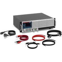
Download the instructions for your Electronic test device in PDF format for free! Find your manual S-LS-118 - Stamos and take your electronic device back in hand. On this page are published all the documents necessary for the use of your device. S-LS-118 by Stamos.
USER MANUAL S-LS-118 Stamos
text_image
31.4 °C 16 58 Scan 42% OUTPUT: 00 000Vtext_image
USB current MODE:CC ScaThis User Manual has been translated for your convenience using machine translation. Reasonable efforts have been made to provide an accurate translation; however, no automated translation is perfect nor is it intended to replace human translators. The official User Manual is the English version. Any discrepancies or differences created in the translation are not binding and have no legal effect for compliance or enforcement purposes. If any questions arise related to the accuracy of the information contained in the User Manual, please refer to the English version of those contents which is the official version.
Technical data
Note: The specifications below are tested under the conditions of temperature 25^ C +5^ C and the warm-up for 20 minutes.
| Product name | DC Electronic Load | ||
| Model | Model S-LS-118 | ||
| Input Rating | Power | 500 W | |
| Voltage | 0-150 V | ||
| Current | 0-40 A | ||
| CC Mode | Range | 0-3A | 0-40A |
| Resolution | 0.1 mA | 1 mA | |
| Accuracy | ±(0.05 % of set+0.045 % off.s) | ||
| CV Mode | Range | 0-18V | 0-150V |
| Resolution | 0.1 mV | 1 mV | |
| Accuracy | ±(0.05 % of set + 0.025 % off.s) | ||
| CR Mode | Range | 0.2 Ω - 7.5 KΩ | |
| Resolution | 16 bit | ||
| Accuracy | ±(0.05 % of set + 0.025 % off.s) | ||
| CW Mode | Range | 500 W | |
| Resolution | 0.01 W | ||
| Accuracy | ±(0.1 % of set + 0.1 % off.s) | ||
| Slope | Range | 0-3A | 0-40A |
| Rising | 0.0001-0.3A/μs | 0.001-2A/ μs | |
| Falling | 0.0001-0.3A/ μs | 0.001-2A/μs | |
| Voltage measurement | Range | 0-18 V | 0-150 V |
| Resolution | 0.1 mV | 1 mV | |
| Accuracy | ±(0.03 % of set + 0.025 % off.s) | ||
| Current measurement | Range | 0-3A | 0-40A |
| Resolution | 0.1 mA | 1 mA | |
| Accuracy | ±(0.05 % of set + 0.045 % off.s) | ||
| Power measurement | Range | 500 W | |
| Resolution | 0.1W | ||
| Accuracy | ±(0.1 % of set + 0.1 % off.s) | ||
| Over power protection | 525 W | ||
| Over current protection | 42 A | ||
| Over voltage protection | 155 V | ||
| Over temperature protection | 85°C | ||
| Input impedance | >150 KΩ | ||
| Weight | 6.5kg | ||
| Dimension (W*D*H) | 215 mm x 388 mm x 150.5 mm | ||
1. General description
The user manual is designed to assist in the safe and trouble-free use of the device. The product is designed and manufactured in accordance with strict technical guidelines, using state-of-the-art technologies and components. Additionally, it is produced in compliance with the most stringent quality standards.
DO NOT USE THE DEVICE UNLESS YOU HAVE THOROUGHLY READ AND UNDERSTOOD THIS USER MANUAL.
To increase the product life of the device and to ensure trouble-free operation, use it in accordance with this user manual and regularly perform maintenance tasks. The technical data and specifications in this user manual are up to date. The manufacturer reserves the right to make changes associated with quality improvement. The device is designed to reduce noise emission risks to a minimum, taking into account technological progress and noise reduction opportunities.
Legend
 | The product satisfies the relevant safety standards. | |
 | Read instructions before use. | |
 | The product must be recycled. | |
 | WARNING! or CAUTION! or REMEMBER! Applicable to the given situation.(general warning sign) | |
 | ATTENTION! Electric shock warning! | |
 | Only use indoors. |

PLEASE NOTE! Drawings in this manual are for illustration purposes only and in some details may differ from the actual product.
2. Usage safety

ATTENTION! Read all safety warnings and all instructions. Failure to follow the warnings and instructions may result in electric shock, fire and/or serious injury or even death.
The terms "device" or "product" are used in the warnings and instructions to refer to:
DC Electronic Load
2.1. Electrical safety
a) The plug must fit the socket. Do not modify the plug in any way. Using original plugs and matching sockets reduces the risk of electric shock.
b) Avoid touching earthed elements such as pipes, heaters, boilers and refrigerators. There is an increased risk of electric shock if the earthed device is exposed to rain, comes into direct contact with a wet surface or is operating in a damp environment. Water getting into the device increases the risk of damage to the device and of electric shock.
c) Do not touch the device with wet or damp hands.
d) Use the cable only for its designated use. Never use it to carry the device or to pull the plug out of a socket. Keep the cable away from heat sources, oil, sharp edges or moving parts. Damaged or tangled cables increase the risk of electric shock.
e) If using the device in a damp environment cannot be avoided, a residual current device (RCD) should be applied. The use of an RCD reduces the risk of electric shock.
f) Do not use the device if the power cord is damaged or shows obvious signs of wear. A damaged power cord should be replaced by a qualified electrician or the manufacturer's service centre.
g) To avoid electric shock, do not immerse the cord, plug or device in water or other liquids. Do not use the device on wet surfaces.
h) The device must be connected to a grounded socket.
2.2. Safety in the workplace
a) Do not use the device in a potentially explosive environment, for example in the presence of flammable liquids, gases or dust. The device generates sparks which may ignite dust or fumes.
b) If you discover damage or irregular operation, immediately switch the device off and report it to a supervisor without delay.
c) If there are any doubts as to the correct operation of the device, contact the manufacturer's support service.
d) Only the manufacturer's service point may repair the device. Do not attempt any repairs independently!
e) In case of fire, use a powder or carbon dioxide (CO2) fire extinguisher (one intended for use on live electrical devices) to put it out.
f) Use the device in a well-ventilated space.
g) Regularly inspect the condition of the safety labels. If the labels are illegible, they must be replaced.
h) Please keep this manual available for future reference. If this device is passed on to a third party, the manual must be passed on with it.
i) Keep packaging elements and small assembly parts in a place not available to children.
j) Keep the device away from children and animals.
k) If this device is used together with another equipment, the remaining instructions for use shall also be followed.

Remember! When using the device, protect children and other bystanders.
2.3. Personal safety
a) Do not use the device when tired, ill or under the influence of alcohol, narcotics or medication which can significantly impair the ability to operate the device.
b) The device is not designed to be handled by persons (including children) with limited mental and sensory functions or persons lacking relevant experience and/or knowledge unless they are supervised by a person responsible for their safety or they have received instruction on how to operate the device.
c) When working with the device, use common sense and stay alert. Temporary loss of concentration while using the device may lead to serious injuries.
d) The device is not a toy. Children must be supervised to ensure that they do not play with the device.
2.4. Safe device use
a) Do not overload the device. Use the appropriate tools for the given task. A correctly-selected device will perform the task for which it was designed better and in a safer manner.
b) Do not use the device if the ON/OFF switch does not function properly (does not switch the device on and off). Devices which cannot be switched on and off using the ON/OFF switch are hazardous, should not be operated and must be repaired.
c) Disconnect the device from the power supply before commencement of adjustment, cleaning and maintenance. Such a preventive measure reduces the risk of accidental activation.
d) When not in use, store in a safe place, away from children and people not familiar with the device who have not read the user manual. The device may pose a hazard in the hands of inexperienced users.
e) Keep the device in perfect technical condition. If damage is discovered, hand over the device for repair before use.
f) Keep the device out of the reach of children.
g) Device repair or maintenance should be carried out by qualified persons, only using original spare parts. This will ensure safe use.
h) To ensure the operational integrity of the device, do not remove factory-fitted guards and do not loosen any screws.
i) The device is not a toy. Cleaning and maintenance may not be carried out by children without supervision by an adult person.
j) It is forbidden to interfere with the structure of the device in order to change its parameters or construction.
k) Keep the device away from sources of fire and heat.
I) Do not short live leads.
m) Do not place the device close to combustible materials.
n) Some parts of the device may get hot. Be careful when touching the device, as this may result in burns.
o) Replace the fuse only with the same type as the original.
p) Before replacing a blown fuse, make sure that the cause of blowing has been eliminated.
q) Unplug the power cord before replacing the fuse.
r)

ATTENTION! Despite the safe design of the device and its protective features, and despite the use of additional elements protecting the operator, there is still a slight risk of accident or injury when using the device. Stay alert and use common sense when using the device.
3. Use guidelines
The device is designed for measurements, voltage adjustment, short-circuit simulation, static and dynamic testing of power supplies, batteries, DC - DC converters and battery chargers.
The user is liable for any damage resulting from unintended use of the device.
3.1. Device description / Device use
APPLIANCE LOCATION
The temperature of environment must not be higher than 40^ C and the relative humidity should be less than 85%. Ensure good ventilation in the room in which the device is being used. There should be at least 10 cm distance between each side of the device and the wall or other objects. The device should always be used when positioned on an even, stable, clean, fireproof and dry surface, and be out of the reach of children and persons with limited mental and sensory functions. Position the device such that you always have access to the power plug. The power cord connected to the appliance must be properly grounded and correspond to the technical details on the product label.
Main interface:
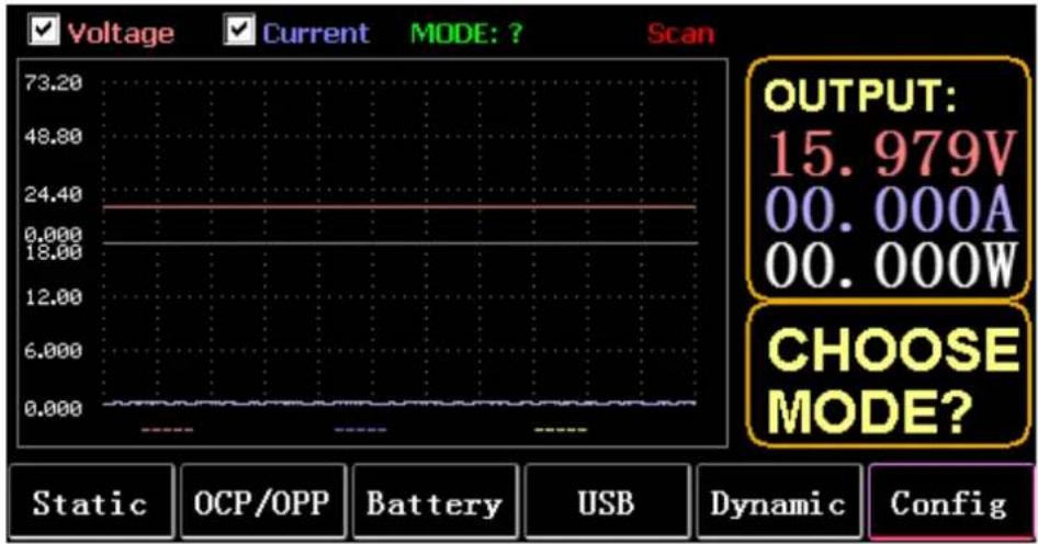
line
| Parameter | Value | | ------------- | --------- | | OUTPUT | 15.979V | | OCP/OPP | 00.000A | | MODE | 00.000W | | CHOOSE MODE | - |Menu keys:
| STATIC (F1) | Enter static CC, CV, CW CR, or SHORT |
| OCP/OPP (F2) | call tables OCP and OPP |
| BATTERY (F3) Battery measurement made: VI curve | |
| USB(F4) | The panel will display the USB logo after inserting the U disk, and it will display blank when it is not inserted. Save data to U disk, import and export LIST to U disk. |
| DYNAMIC(FS) | Dynamic CC, CV, CW, CR, RL, or PL |
| CONFIG(F6) Parameter settings | |
Keyboard function:
| ESC | key for escape and delete |
| F1 to F6 | Function keys |
| TAB | Change focus |
| STOP | 1. Pause during waveform display |
| 2. Long press to take a screenshot | |
| LOCK | Long press to lock the keyboard, and long press again to unlock it |
| CC | 1. Short press to enter CC mode |
| 2. Long press SHORT | |
| CV | Enter CV mode |
| ew | Enter CW mode |
| CR | Enter CR mode |
| 0 to 9 | 1. Short press the number keys |
| 2. Long press numeric 1 to 6 to call static storage units 1 to 6 | |
| 3. Long press 7 to set RTC, and long press aga in to save and exit | |
| 4. Long press 8 set LCD backlight, and long press again to save and exit | |
| 5. Long press 9 to enable the USB storage, and long press again to turn off the storage | |
| 6. In the main interface, long press numeric 0 for more than 3s to calibrate 0 | |
| WAVE | Press TAB to select voltage or current, and press WAVE to display 4 measurement lines, among which 2 vertical lines measure time, and 2 horizontal lines measure voltage and current amplitude respectively. |
| 1. Short press ← (left key) to select the vertical line on the left | |
| 2. Short press → (right key) to select the vertical line on the right, and long press after STOP to move the waveform to the right | |
| 3. Short press ↑ (up key) to select the measured voltage amplitude, and long press to modify the voltage scale value | |
| 4. Short press ↓ (down key) to select the measured current amplitude, and long press to modify the current scale value | |
| 5. Enter to adjust the sampling time value | |
| ON | Turn on and turn off |
| Enter | 1. Short press to enter |
| 2. Long press to save | |
| Note: | The long press time is about 1.5s |
3.2. Static mode
3.2.1. Static CC
In constant current mode, the load consumes a constant current regardless of whether the input voltage is changed.
Operations:
1) Press CC or the soft key FI on the keyboard.
2) Enter a value from O to 9 on the numeric keypad.
3) Press f-- and to move the cursor, and press 1' and knob to adjust the corresponding value.
4) Press ENTER to turn ON/OFF.
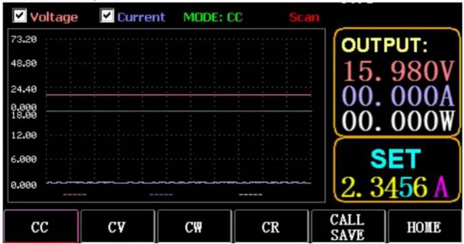
line
| Parameter | Value | | --------- | --------- | | OUTPUT | 15.980V | | 00.000A | 00.000A | | 00.000W | 00.000W | | SET | 2.3456 A |3.2.2. Static CV
In constant voltage mode, the load keeps the device under test at the set voltage regardless of whether the input current is changed.
Operations: same as above
3.2.3. Static CW
In constant voltage mode, the load keeps the device under test at the set power regardless of whether the input voltage and current are changed. Operations: same as above
3.2.4. Static CR
In constant resistance mode, the load keeps the device under test at the set resistance regardless of whether the input voltage and current are changed. Operations: same as above
3.2.5. SHORT function
In SHORT made, the load is output at the maximum current. Operations:
Long press CC to displays MODE: SHORT on the interface and press CC, CV, CW to exit.
3.2.6. Call static storage
The load can stare and call 100 groups of static set values.
1) Storage operation
(1) Press CAL/SAVE to switch the state to SAVE.
(2) Enter a number key to index a line in the list, press TAB to select it, and press ENTER to enter the edit made. Edit to display a red background, and press and to select.
(3) Edit MODE. Press CC, CV, CW, or CR on the keyboard to modify.
(4) Edit data. Press 0 to 9 and ESC on the keyboard to modify.
(5) After modification, press ENTER, and long press ENTER again to save the data.
2) Call operation
(1) Press CALL/SAVE to switch to CALL.
(2) Enter a number key to index a line or press TAB to switch the list, select it with the knob, and press ENTER.
3) M1 to M6 quick call
(1) Long press numeric 1 to 6 to call M1 to M6.
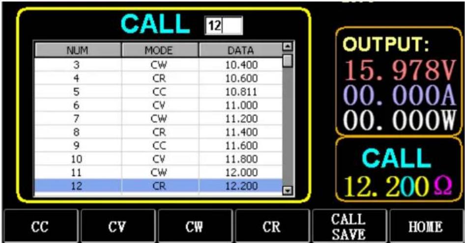
text_image
CALL 12 NUM MODE DATA 3 CW 10.400 4 CR 10.600 5 CC 10.811 6 CV 11.000 7 CW 11.200 8 CR 11.400 9 CC 11.600 10 CV 11.800 11 CW 12.000 12 CR 12.200 OUTPUT: 15.978V 00.000A 00.000W CALL 12.200Ω CC CV CW CR CALL SAVE HOME3.3. Dynamic Test Mode
In dynamic mode, the load is constantly switching between 2 different values A and B.
3.3.1. Dynamic CC
For output using two different currents with different duty cycles at a certain frequency.
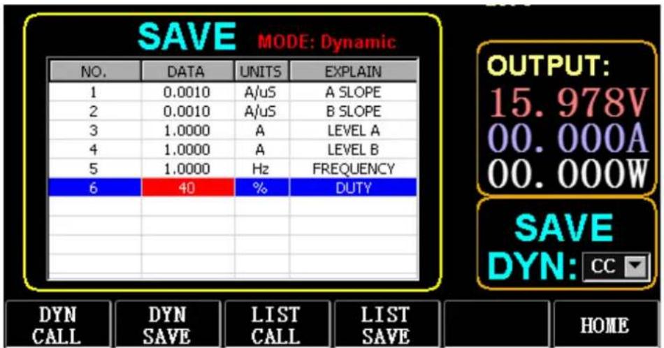
Take the current slope A of 0.001A/μS, the current change slope B of 0.002A/μS, the current value A of 1A, the current value B of 2A, the cycle frequency of 1HZ, and the duty cycle of 40% as an example.
Operations:
Select (FS) Dynamic to enter the interface as shown in Fig. 3.1.
1) Press (F1) DYN/CALL, press TAB to select CALLDYN's drop-down box, and turn the knob to CC.
2) Press (F2) DYN/SAVE to display SAVE on the screen.
3) Press TAB to switch the focus. The knob selects the first row.
4) Press ENTER to select the red background.
5) Enter numeric 0 to 9, and ESC.
6) After editing as 0.001, press ENTER. The n 0.0010 will be displayed on the screen, and the background will be switched to blue.
7) Repeat the above steps to set 0.002A/μS, 1A, 2A, 1HZ, and 40% respectively.
8) Long press ENTER to save the edited data.
9) Press the soft key (F1) DYN/CALL to display CALL.
10) Press ENTER to call.
11) Turn ON/OFF.
text_image
SAVE MODE: Dynamic NO. DATA UNITS EXPLAIN 1 0.0010 A/uS A SLOPE 2 0.0010 A/uS B SLOPE 3 1.0000 A LEVEL A 4 1.0000 A LEVEL B 5 1.0000 Hz FREQUENCY 6 40 % DUTY DYN CALL DYN LIST CALL LIST SAVE HOME OUTPUT: 15.978V 00.000A 00.000W SAVE DYN: CC ✓Fig. 3.1 DYN CC
Note:
Set the slope and current value to be range dependent. The maximum slope of the small range is 0.24A/ S , the maximum current can be set to 3A, the maximum slope of the large range is 3.2A/ S , and the maximum current can be set to 40A.
The maximum frequency can be set to 40,000Hz. When the frequency is set to 40,000Hz, the maximum duty cycle is 50%.
Refer to Section "Load maximum setting" for the current maximum setting.
3.3.2. Dynamic CV
Used for output with different duty cycles at two different voltages at a certain frequency.
Take the A voltage of 1V, the B voltage of 2V, the cycle frequency of 1 Hz, and the duty cycle of 40% as an example.
Operations:
1) Press (F1) DYN/CALL, TAB to select DYN/CALL, and turn the knob to CV.
2) Press (F2) DYN/SAVE to display SAVE on the screen.
3) Press TAB to switch the focus and turn the knob to select the first row.
4) Press ENTER to select the red background.
5) Enter numeric 0 to 9, and ESC.
6) After editing as 1.0001, press ENTER. Then 1.0000 will be displayed on the screen, and the background will be switched to blue.
7) Repeat the above steps to set 2V, 1 HZ, and 40% respectively.
8) Long press ENTER to save the edited data.
9) Press (F1) DYN/CALL to display CALL.
10) Press ENTER to call DYN CV.
11) Turn ON/OFF.
3.3.3. Dynamic CW
The operation is the same as above.
3.3.4. Dynamic CR
The operation is the same as above.
3.3.5. Dynamic PL
It is set to the value A at the beginning. Each time a trigger signal is received, the load is switched to the value B, and switched to the value A aga in after the set time is maintained.
The following takes the current slope A of 0.001 A/ S, the current slope B of 0.002 A/uS, the current value A of 1 A, the current value B of 2A, and the duration B of 1s as an example.
Operations:
1) Press (F1) DYN/CALL, press TAB to select CALLYN, and turn the knob to PL.
2) Press (F2) DYN/SAVE to display SAVE on the screen.
3) Press TAB to switch the focus and turn the knob to select the first row.
4) Press ENTER to select the red background.
5) Enter numeric 0 to 9, and ESC.
6) After editing as 0.001, press ENTER. Then 0.0010 will be displayed on the screen, and the background will be switched to blue.
7) Repeat the above steps to set 0.002A/uS, 1A, 2A, and 1a respectively.
8) Long press ENTER to save the edited data.
9) Press the soft key (F1) DYN/CALL to display CALL.
10) Press ENTER to call DYN RL.
11) Turn ON/OFF.
12) Trigger the value B every time you press ENTER.
3.3.6. Dynamic RL
Each time a trigger signal is received, the load is switched back and forth between the value A and the value B.
Take the current slope A of 0.001 A/ S, the current slope B of 0.002A/ S, the current value A of 1A, and the current value B of 2A as an example. Operations:
1) Press (F1) DYN/CALL, press TAB to select DYN/CALL, and turn the knob to RL.
2) Press (F2) DYN/SAVE to display SAVE on the screen.
3) Press TAB to switch the focus and turn the knob to select the first row.
4) Press ENTER to select the red background.
5) Enter numeric 0 to 9, and ESC.
6) After editing as 0.001, press ENTER. The n 0.0010 will be displayed on the screen, and the background will be switched to blue.
7) Repeat the above steps to set 0.002A/ S, 1A, and 2A respectively.
8) Long press ENTER to save the edited data.
9) Press the soft key (F1) DYN/CALL to display CALL.
10) Press ENTER to call DYN RL.
11) Turn ON/OFF.
12) Trigger the value B every time you press ENTER.
3.4. Sequential Operation Mode
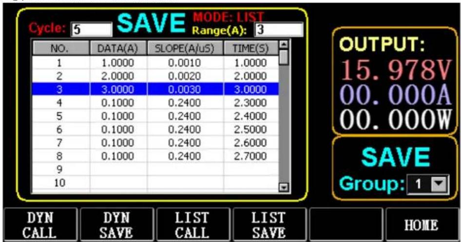
A maximum of 7 groups can be stored, each group can set up to 84 dynamically changing currents, and then the set currents can be switched in sequence. Take the settings stored in Group 1, the maximum current of 3A, and the number of the dynamic change current of 3;, the first dynamic current of 1A, the change rate of 0.001 A/uS, and the duration of 1s; the second dynamic current of 2A, the change rate of 0.002A/uS, and the duration of 2s; the third dynamic current of 3A, the change rate of 0.003A/ S, and the duration of 3s; the number of repeated operations of 5 as an example. As shown in Fig. 4.1 List.
Operations:
1) Press (F3) LIST/CALL press TAB to select GROUP, and turn the knob to Group 1.
2) Press (F4) LIST/SAVE to display SAVE on LIST.
3) Press TAB to switch the focus, select RANGE and edit the maximum value of 3A via numeric 0 to 9 and ESC.
4) Press TAB to select CYCLE. The number of editing cycles is 5.
5) Press TAB to the first row of LIST and press ENTER. At this time, the background turns red.
Edit the first item DATA value of 1A. After editing, press ENTER, and the background will be switched to blue.
Press left and right keys ( and ) to the second item SLOPE (A/ S), edit the value as 0.001A/uS, and press ENTER, and the background will be switched to blue. Press left and right keys ( and ) to the third item TIME (S), edit the value as 1s, and press ENTER.
6) Repeat the above steps to start setting the second and third rows of the table.
7) Long press ENTER to save the edited data.
8) Press the soft key (F3) LIST/CALL to display CALL.
9) Press ENTER to call LIST1.
10) Turn ON/OFF.
Note:
To delete data after Row 3, select Row 4 in LIST SAVE made.
Press ENTER to enter the editing background and it turns red, and then press ESC to delete all data after Row 4. Long press ENTER to save the data.
text_image
Cycle: 5 SAVE MODE: LIST Range(A): 3 NO. DATA(A) SLOPE(A/uS) TIME(S) 1 1.0000 0.0010 1.0000 2 2.0000 0.0020 2.0000 3 3.0000 0.0030 3.0000 4 0.1000 0.2400 2.3000 5 0.1000 0.2400 2.4000 6 0.1000 0.2400 2.5000 7 0.1000 0.2400 2.6000 8 0.1000 0.2400 2.7000 9 10 OUTPUT: 15.978V 00.000A 00.000W SAVE Group: 1 DYN CALL DYN SAVE LIST CALL LIST SAVE HOMEFig. 4.1 LIST
3.5. Battery Test Mode
A maximum of 7 groups of battery test parameters can be set, the battery is tested according to the set current, voltage, capacity, time, and the test is automatically turned off if one of the conditions is met.
3.5.1. Battery test setup
Operation instructions: it takes the settings stored in Group 1, the current range of 10A, the discharge current of 1A, the discharge cut-off voltage of 2V, the discharge cut-off capacity of 0.5Ah, and the discharge duration of 200m (battery time unit: m) as an example
1) Press (F3) Battery on the main interface to enter battery measurement.
2) Press (F1) BATT/CALL, and press TAB to select CALL GROUP 1.
3) Press (F2) BATT/SAVE to display SAVE on the table.
4) Press TAB to switch the focus and turn the knob to select the row position that needs to be modified.
5) Press ENTER to select the red background.
6) Enter numeric 0 to 9, and ESC.
7) After editing the range of 10A, press ENTER. Then 10.000 will be displayed on the screen, and the background will be switched to blue
8) Repeat the above steps to set 1A, 2V, 0.5Ah, and 200m respectively.
9) Long press ENTER to save the edited data.
10) Press (F1) BATT/CALL.
11) Press ENTER to call.
12) Turn ON/OFF.
3.6. VI Curve Mode
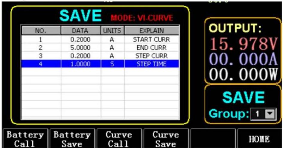
A maximum of 7 groups of VI test parameters can be set according to the set maximum current, minimum current, and step value.
text_image
SAVE MODE: VI-CURVE NO. DATA UNITS EXPLAIN 1 0.2000 A START CURR 2 5.0000 A END CURR 3 0.2000 A STEP CURR 4 1.0000 S STEP TIME Battery Call Battery Save Curve Call Curve Save HOME OUTPUT: 15.978V 00.000A 00.000W SAVE Group: 1Fig. 6.1 VI Current Parameters
3.6.1. VI test setup
Operation instructions: it takes the settings stored in Group 1, the start current of 0.2A, the end current of SA, the step current of 0.2A, and the step duration of ls as an example.
1) Press (F3) Battery on the main interface to enter VI measurement.
2) Press (F3) Curve/CALL, and press TAB to select CALL GROUP 1
3) Press (F4) Curve/SAVE to display SAVE on the table.
4) Press TAB to switch to the table focus and turn the knob to select the row position to be modified.
5) Press ENTER to select the red background.
6) Press ENTER to select the red background.
7) After editing as 0.2, press ENTER. Then 0.2000 will be displayed on the screen, and the background will be switched to blue.
8) Repeat the above steps to set 5A, 2A, and 1.000s respectively.
9) Long press ENTER to save the edited data.
10) Press (F3) Curve/CALL.
11) Press ENTER to call.
12) Turn ON/OFF.
The operation effect is shown in Fig. 6.2
Fig. 6.2 VI Running Interface
3.7. OCP Mode
When the voltage reaches the VON value, the current output will be delayed for a period of time, and the step value will be decreased once every other period of time until the cut-off current or the voltage is higher than the OCP set voltage. If the stopped voltage is higher than the OCP voltage and the current is between the set maximum and minimum value, it is PASS, otherwise it is FAULT.
3.7.1. Setting function of OCP test
Note: 7 groups of OCP test parameters can be set at most.
Operation instructions: it takes the setting stored in Group 1, VON voltage of 10V, VON voltage delay of 5S, and current range of 3A; start current of 2A, each decrease of 0.1A, and each decreasing duration of 1s; end current of 1A, OCP voltage of 8V, maximum current of 1.9A, and minimum current of 1,1A as an example.
Fig. 7.1 OCP
1) Press (F2) OCP/OPP on home page.
2) Press (F1) OCP/CALL and TAB to select CALL GROUP 1.
3) Press (F2) OCP/SAVE to display SAVE on the table.
4) Press TAB to switch the focus and turn the knob to select the first row.
5) Press ENTER to select red background. Enter numeric O to 9, and ESC.
6) After editing VON as 10V, press ENTER. Then 10.000 will be displayed on the screen, and the background will be switched to blue.
7) Repeat the above steps to set 5S, 3A, 2A, 0.1A, 1S, 1A, 8V, 1.9A, and 1.1A respectively.
8) Long press ENTER to save the edited data.
9) Press (F1) OCP/CALL.
10) Press ENTER to call.
11) Turn ON/OFF.
3.8. OPP Mode
When voltage reaches the VON value, the power output should be delayed for a period of time, and the step value should be decreased every once in a while until cut-off power or voltage is higher than the OPP set voltage. After the delay and decrease stop, if the voltage is higher than OPP voltage, the power between the set maximum and minimum values means PASS, or it means FAULT.
3.8.1. Setting function of OPP test
7 groups of OPP test parameters can be set at most.
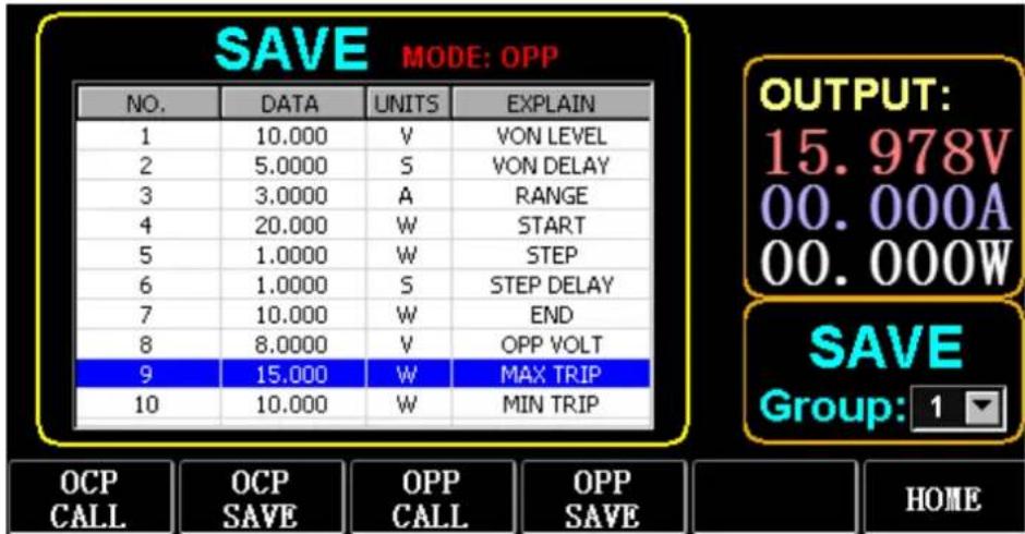
Operation instructions: it takes the setting stored in Group 1, VON voltage of 10V, VON voltage delay of 5S, and current range of 3A; start power of 20W, each decrease of 1W, and each decreasing duration of 1s; end power of 10W, OPP voltage of 8V, maximum power of 15W, and minimum power of 10W as an example.
text_image
SAVE MODE: OPP NO. DATA UNITS EXPLAIN 1 10.000 V VON LEVEL 2 5.0000 S VON DELAY 3 3.0000 A RANGE 4 20.000 W START 5 1.0000 W STEP 6 1.0000 S STEP DELAY 7 10.000 W END 8 8.0000 V OPP VOLT 9 15.000 W MAX TRIP 10 10.000 W MIN TRIP OUTPUT: 15.978V 00.000A 00.000W SAVE Group: 1 OCP CALL OCP SAVE OPP CALL OPP SAVE HOMEFig. 8.1 OPP
1) Press (F2) OCP/OPP on home page.
2) Press (F3) OPP/CALL and TAB to select CALL GROUP 1.
3) Press (F4) OPP/SAVE to display SAVE on the table.
4) Press TAB to switch the focus and turn the knob to select the first row.
5) Press ENTER to select DATA in the first row and display the red background.
6) Enter numeric 0 to 9, and ESC.
7) After editing VON as 10V, press ENTER. Then 10.000 will be displayed on the screen, and the background will be switched to blue.
8) Repeat the above steps to set 5S, 3A, 20W, 1W, 1S, 10W, 8V, 15W, and 10W respectively.
9) Long press ENTER to save the edited data.
10) Press (F3) OCP/CALL.
11) Press ENTER to call.
12) Turn ON/OFF.
3.9. WAVE Mode
3.9.1. WAVE measurement
1) Press TAB to display voltage, current and waveform.
2) Press WAVE to display the measuring column.
1) Press TAB to display voltage, current and waveform. 2) Press WAVE to display the measuring column.
3) Measure the time scale. Press or to select the left or right measuring column, and turn the knob to move left or right for the display of the difference between the two measuring lines.
4) Measure the negative value of voltage or current. Press ↑ or ↓ to select the upper or lower measuring column, and turn the knob to move up or down for the display of amplitude of the current measuring column.
5) Adjust the scale value of current. Long press ↓ and turn the knob to adjust the size.
6) Adjust the scale value of voltage. Long press ↑ and turn the knob to adjust the size.
7) Adjust the time value of sampling. Press ENTER and turn the knob to adjust the size.
8) When the wave pauses, press STOP.
Take the measurement of DYN CC made as an example.
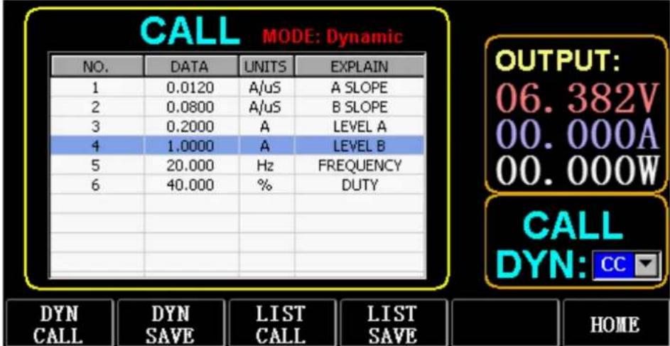
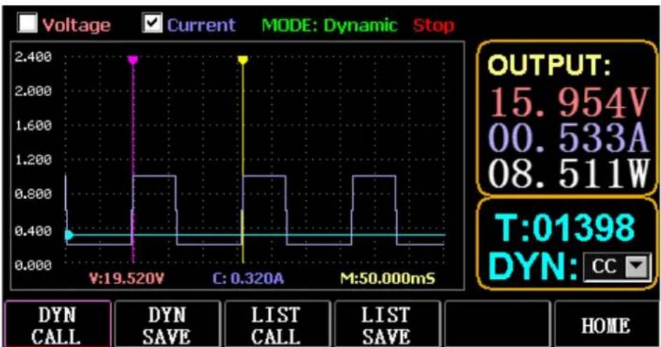
After editing the data of DYN CC, A SLOPE is 0.012 A/ S, B SLOPE is 0.08 A/ S, A is 0.2A, B is 1A, frequency is 20 Hz, duty cycle is 40%, as shown in Fig. 9.1. Please see Fig. 9.2 for the waveform measurement.
text_image
CALL MODE: Dynamic NO. DATA UNITS EXPLAIN 1 0.0120 A/uS A SLOPE 2 0.0800 A/uS B SLOPE 3 0.2000 A LEVEL A 4 1.0000 A LEVEL B 5 20.000 Hz FREQUENCY 6 40.000 % DUTY DYN CALL DYN LIST LIST SAVE CALL SAVE HOME OUTPUT: 06.382V 00.000A 00.000W CALL DYN: CCFig. 9.1
line
| Time (ms) | Voltage (V) | Current (A) | |-----------|-------------|-------------| | 0 | 0.400 | 0.400 | | 19.520 | 2.400 | 0.400 | | 3.20 | 0.400 | 0.400 | | 50.00 | 2.400 | 0.400 |Fig. 9.2 Waveform Measurement
3.10. Setting of Parameter Function
text_image
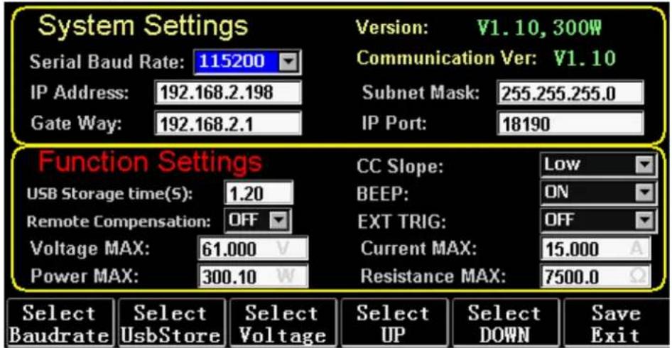
System Settings Serial Baud Rate: 115200 IP Address: 192.168.2.198 Gate Way: 192.168.2.1 Function Settings USB Storage time(S): 1.20 Remote Compensation: OFF Voltage MAX: 61.000 V Power MAX: 300.10 W Version: V1.10,300W Communication Ver: V1.10 Subnet Mask: 255.255.255.0 IP Port: 18190 CC Slope: Low BEEP: ON EXT TRIG: OFF Current MAX: 15.000 A Resistance MAX: 7500.0 Ω Select Select Select Select Select Save Baudrate UsbStore Voltage UP DOWN ExitFig. 10.1 Parameter Setting
| Select Baudrate(F1) | Select the parameter of baud rate |
| Select UsbStore(F2) | Switch focus to select USB sto re |
| Select Voltage(F3) | Switch the Max setting of focus voltage |
| Select UP(F4) Switch | Switch the focus up |
| Select DOWN(F5) Switch | Switch the focus down |
| Save Exit(F6) | Save and exit |
3.10.1. Setting of communication interface
1) Setting of serial baud rate
Select TAB or (FI) SelBaudrate to tum the knob
(1) Setting of IP address
ESC on the keyboard is the delete key, and numeric 0 to 9 is for entering numbers.
(2) Setting of port number
ESC on the keyboard is the delete key, and numeric O to 9 is for entering numbers. The maximum port number is 65535, and the minimum port number is 1000. The value 18191 can not be set.
3.10.2. Setting of CC slope rate
Press TAB to switch to CC SLOPE and turn the knob to select LOW/HIGH.
3.10.3. Storage time setting of USB flash disk
Press TAB to switch to Sel UsbStore. ESC is the delete key, and numeric 0 to 9 is for entering numbers. The minimum storage time can only be 0.05S, and the maximum storage time is 9999S;
3.10.4. Buzzer setting
Press TAB to switch to BEEP and turn the knob to select ON/OFF.
3.10.5. Setting of remote compensation
Press TAB to switch to Remote Comp, select ON, and connect the output end of the object to be tested to the terminal sense(+) or sense(-) on the front panel (this function is not saved during the blackout, otherwise it is closed).
3.10.6. Setting of external triggering
Press TAB to switch to EXI P TRIG and turn the knob to select Trig On/Switch On/OFF.
Trig On: triggering switch (open load after triggering)
Switch on: remote switch (ON/OFF function on the front panel will not work when this function works).
3.10.7. Setting of maximum values
1) Maximum voltage
Press TAB to switch to Voltage. ESC is the delete key, and numeric 0 to 9 is for entering numbers. The maximum voltage is 150V.
2) Maximum current
Press TAB to switch to Current. ESC is the delete key, and numeric 0 to 9 is for entering numbers. The maximum current is 40A.
3) Maximum power
Press TAB to switch to Power. ESC is the delete key, and numeric 0 to 9 is for entering numbers. The maximum power depends on the model.
4) Maximum resistance
Press TAB to switch to Resistance. ESC is the delete key, and numeric 0 to 9 is for entering numbers. The maximum resistance is 7500R.
Note: 18V and below is set to be the low voltage range (0 to 18V), and above
- 4V is set to be the high voltage range (0 to 150V).
3A and below is set to be the low current range (0 to 3A), and above 3.1A is set to be the high current range (O to 40A).
OVP alarm value: it is (19.4V) at the low range and (155V) at the high range. OCP alarm value: it is 105% of the set current value. For example, if the current is set to be SA, the alarm value is 5.25A.
OPP alarm value: it is 105% of the set power value. For example, if the power value is set to be 100W, the alarm value is 105W.
OTP alarm value: if the temperature is higher than 85, an alarm will begiven, and the load will be closed.
3.10.8. RTC setting
Long press numeric 7, and then date will be displayed on the screen as shown in Fig. 10.2.
Fig. 10.2 RTC Date
Press or to move the focus and turn the knob to make modification. After modification, long press ENTER or numeric 7 to save, and press ESC to exit.
3.10.9. Backlight setting
After long pressing numeric 8, the progress bar will be displayed on the screen as shown in Fig. 10.3.
text_image
31.4 °C 16 58 Scan 42% OUTPUT: 00 000VFig. 10.3 Backlight
Turn the knob to adjust the brightness, long press ENTER or numeric 8 to save, and press ESC to exit.
3.10.10. 0 calibration function
If the device has not been calibrated for a long time or the temperature is high or low, the data will not return to zero, and the 0-calibration function can be performed.
After entering home page, close the load, unplug the external test line, and long press numeric 0 for over 3 seconds for the 0 calibration of voltage and current. And the 0-calibration function will disappear when the load restarts, and 0-calibrate again when needed.
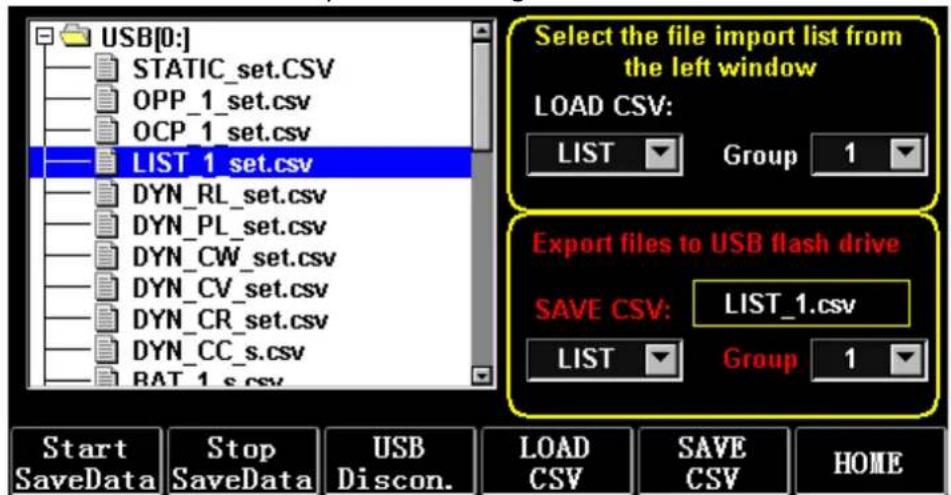
3.11. U Flash Disk Import and Export Function
Save real-time voltage and current data and export data list through U flash disk. As shown in Fig. 11.1, the USB[0] tree on the left shows that the file list is the acceptable format data loaded in the U flash disk. And the upper part on the right is the option of importing the load from the U flash disk, and the lower part is the data option of exporting the load to the U flash disk.
Press TAB to select the control. Press to move the focus left or right.
Press F4 (Load CSV) to import the file from the USB flash disk, and save CSV (FS) to export the CSV file to the USB flash disk. And the function keys are shown in Fig. 11.2 below:
text_image
USB[0:] STATIC_set.CSV OPP_1_set.csv OCP_1_set.csv LIST_1_set.csv DYN_RL_set.csv DYN_PL_set.csv DYN_CW_set.csv DYN_CV_set.csv DYN_CR_set.csv DYN_CC_s.csv BAT_1_s.csv Select the file import list from the left window LOAD CSV: LIST Group 1 Export files to USB flash drive SAVE CSV: LIST_1.csv LIST Group 1 Start Stop USB SaveData SaveData Discon. LOAD SAVE HOME LOAD CSV CSV HOMEFig. 11.1 Storage Interface of USB Flash Disk
| Start SaveData(F1) | Create a CSV file with date as its name |
| Stop SaveData(F2) Stop writing files | |
| USB Disconnect(F3) | Disconnect USB |
| LoadCSV{F4} Import files from USB flash disk | |
| SaveCSV{FS} Export CSV file | |
| HomePage(F6) Home page | |
3.11.1. Import and save LIST
Take the table that data of BAT Group 1 is exported as an example.
1) After the USB flash disk is inserted, USB key is displayed on home page. Press (F4) USB.
2) Press TAB to switch to SAVE, turn the knob to select BAT mode, press ← or → to select Group, and turn the knob to Group 1.
3) After pressing {FS} SAVE CSV, a message will prompt that it has been exported. Import DYN_PL_Set.csv from USB flash disk to DYN PL.
| K12 | fx | |||||
| A | B | C | D | E | ||
| 1 | NO. | DATA(A) | UNITS | EXPLAIN | ||
| 2 | 1 | 1.132 | A/uS | A SLOPE | ||
| 3 | 2 | 1.248 | A/uS | B SLOPE | ||
| 4 | 3 | 1.51 | A | LEVEL A | ||
| 5 | 4 | 3.201 | A | LEVEL B | ||
| 6 | 5 | 6.813 | S | TIME WIDTH | ||
| 7 | ||||||
Fig. 11.3 DYN_PL_Set.csv
4) Press TAB to switch to LOAD, adjust to DYN mode and turn the knob to PL.
5) List a tree of files on the left and turn the knob to select the file DYN_PL Set.CSV to be imported.
6) After pressing (F4) LOAD CSV, successful import will be prompted.
3.11.2. U Flash Disk Storage of Real-time Data of Load Test
If the real-time test data is saved with a U flash disk, the data volume is to save the voltage and current data 5 times per second.
The operation procedures are as follows:
1) Press F6 (Config), use Tab to switch the focus on USB Stare (Fig. 10.1 Parameter Setting).
Use ESC to delete, enter the number key 0.2, which means to save 5 times per second.
2) There are 2 ways to open the save data file.
<1> Turn on or off data saving in the menu interface: enter the U flash disk page (Fig. 11.1 Storage Interface of USB Flash Disk). Press (F1) "Start Save Data" to start, then the top status bar will have a down arrow flashing, indicating that the data is being saved right now.
To stop writing, re-enter the USB flash disk page, the n press (F2) "Stop Save Data". And the top arrow will disappear.
<2> Shortcut key to open or close the operation: in the state of inserting the U flash disk, long press the number key 9 to start the U flash disk saving, and long press the number key 9 again to stop saving.
Refer to Fig. 11.4 Data Write Icon
text_image
USB current MODE:CC ScaFig. 11.4 Data Write Icon
3.12. Cleaning and maintenance
a) Always unplug the device before cleaning or putting it away.
b) Use only non-corrosive cleaners to clean the surface.
c) After cleaning the device, all parts should be dried completely before using it again.
d) Store the unit in a dry, cool place, free from moisture and direct exposure to sunlight.
e) Do not spray the device with a water jet or submerge it in water.
f) Do not allow water to get inside the device through vents in the housing of the device.
g) Clean the vents with a brush and compressed air.
h) The device must be regularly inspected to check its technical efficiency and spot any damage.
i) Use a soft cloth for cleaning.
j) Do not use sharp and/or metal objects for cleaning (e.g. a wire brush or a metal spatula) because they may damage the surface material of the appliance.
k) Do not clean the device with an acidic substance, agents of medical purposes, thinners, fuel, oils or other chemical substances because it may damage the device.
DISPOSING OF USED DEVICES:
Do not dispose of this device in municipal waste systems. Hand it over to an electric and electrical device recycling and collection point. Check the symbol on the product, instruction manual and packaging. The plastics used to construct the device can be recycled in accordance with their markings. By choosing to recycle you are making a significant contribution to the protection of our environment.
Contact local authorities for information on your local recycling facility.

text_image
31.4 °C 16 58 Scan 42% OUTPUT: 00 000Vtext_image
USB current MODE:CC Scatext_image
31.4 °C 16 58 Scan 42% OUTPUT: 00 000VObr. 11.3 DYN\_PL\_Set.csv
Figure 11.3 DYN_PL_Set.csv
text_image
USB current MODE:CC Scatext_image
31.4 °C 16 58 Scan 42% OUTPUT: 00 000Vtext_image
USB current MODE:CC Scatext_image
31.4 °C 16 58 Scan 42% OUTPUT: 00 000VFigura 10.3 Luz de fondo
text_image
USB current MODE:CC Scatext_image
USB current MODE:CC Sca11.4. ábra Data Write Icon
APPARATETS PLACERING
text_image
31.4 °C 16 58 Scan 42% OUTPUT: 00 000Vtext_image
USB current MODE:CC ScaFig. 11.4 Data skrive Icon
For the disposal of the device please consider and act according to the national and local rules and regulations.
CONTACT
expondo Polska sp. z o.o. sp. k.