DEH 100PT - Dehumidifier MSW - Free user manual and instructions
Find the device manual for free DEH 100PT MSW in PDF.

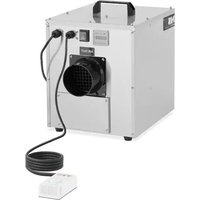
| Product Type | Desiccant wheel dehumidifier |
| Model | MSW-DEH 100PT |
| Rated Voltage | 230 V / 50 Hz |
| Rated Power | 780 W |
| Dimensions (L x W x H) | 46.5 x 26 x 37 cm |
| Weight | 13.05 kg |
| Desiccant Wheel Type | Honeycomb wheel with moisture absorbent |
| Operating Principle | Regeneration by hot air (100-140 °C) |
| Application Area | Indoor (basements, bathrooms, damp rooms) |
| Control Mode | 3-position switch: Off (O), Manual (MAN), Automatic (AUTO) |
| Humidity Control | Integrated hygrostat with adjustable relative humidity level |
| Air Filters | Filters for process air and regeneration air (clean every 15 days) |
| Ventilation | Process air fan and regeneration air fan |
| Safety | Emergency stop via switch, overheat protection, maintenance by professional |
| Routine Maintenance | Filter cleaning every 2 weeks; annual full inspection |
| Available Spare Parts | Filters, drive belt, fuses, heating elements |
| Repairability | Reserved for qualified technician (high voltage and high temperatures) |
| Transport and Storage | Original packaging, covered place protected from frost and rain |
| Compliance | European safety standards |
Frequently Asked Questions - DEH 100PT MSW
User questions about DEH 100PT MSW
0 question about this device. Answer the ones you know or ask your own.
Ask a new question about this device
Download the instructions for your Dehumidifier in PDF format for free! Find your manual DEH 100PT - MSW and take your electronic device back in hand. On this page are published all the documents necessary for the use of your device. DEH 100PT by MSW.
USER MANUAL DEH 100PT MSW
natural_image
Exterior view of a metallic industrial device with black ports and mounting feet (no visible text or symbols)natural_image
Pure schematic diagram of a mechanical or fluidic component with no text, numbers, or symbolsA Entfeuchtungsraum
This User Manual has been translated for your convenience using machine translation. Reasonable efforts have been made to provide an accurate translation; however, no automated translation is perfect nor is it intended to replace human translators. The official User Manual is the English version. Any discrepancies or differences created in the translation are not binding and have no legal effect for compliance or enforcement purposes. If any questions arise related to the accuracy of the information contained in the User Manual, please refer to the English version of those contents which is the official version.
Technical data
| Parameter description | Parameter value |
| Product name | Air dehumidifier |
| Model | MSW-DEH 100PT |
| Rated voltage [V~] / Frequency [Hz] | 230/50 |
| Rated power [W] | 780 |
| Dimensions [Width x Depth x Height; mm] | 46.5 x 26 x 37 |
| Weight [kg] | 13.05 |
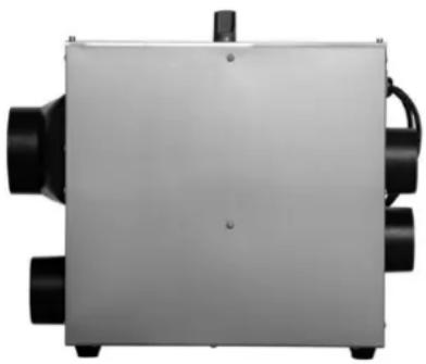
I. Product Framework
natural_image
Exterior view of a metallic industrial device with black ports and mounting holes (no text or symbols visible)II. Product Introduction
2.1 Brief Introduction
The device is designed to remove excess moisture from the air, helping to maintain optimal humidity levels in indoor environments. It is particularly useful in damp areas such as basements, bathrooms, or rooms prone to condensation, reducing the risk of mold and mildew growth. The device improves overall air quality by reducing allergens like dust mites and mold spores, making it beneficial for individuals with respiratory issues.
2.2 Manual Introduction
These manual covers installation, operation, maintenance, and basic troubleshooting, and is designed for the majority of dehumidifier users. Its purpose is to provide essential information to help users understand the structure and function of the machine, guide them on how to install, operate, and maintain the unit, and assist in basic troubleshooting before seeking professional service.
2.3 Safety Instructions
This manual offers guidelines for optimal operation of the dehumidifier, but these recommendations are intended for guidance only and do not assume personal responsibility or adherence to local safety regulations. When installing and operating the dehumidifier, individuals are responsible for the following:
★Care about yourself and others!
★Protect the safety of machine by conforming to the description and instructions of this manual!
The device meets all European standard safety requirements and specifications, with careful consideration given to the safety of both personnel and equipment during its design and manufacture. Each chapter of this manual includes safety information that clearly highlights hazardous operations, and warning symbols are provided as cautionary reminders.
2.4 Operating Principle
- The core structure of the desiccant dehumidifier is a rotating wheel, which is a honeycomb wheel with a moisture absorbent, made of a special composite heat-resistant material. The honeycomb rotating wheel has the characteristics of larger moisture absorption area than surface, low circulation resistance and high dehumidification efficiency.
- On both sides of the wheel, a diaphragm with a high seal performance divides the entire surface into two sectors: the processing sector and the regeneration recovery sector. When processing air that needed dehumidifying enters the processing sector, the water vapor is absorbed by the carrier in the wheel and is dried, and the latent heat is released. The dry air is sent out through the fan. As the absorption of water increases, the processing sector becomes saturated. To maintain its stable dehumidification performance, the saturated
- wheel is transferred to the regeneration sector under the drive of the motor, and the regeneration process starts. Regeneration air reached 100\~140°C by heating, then reverse blowing into the regeneration area. In the high temperature condition, the absorbed moisture in the wheel is desorbed and releases a lot of sensible heat. The
- temperature of itself reduced and it turns into the moist air filled with moisture which is discharged to the outside of the room in the next step, and the water transfer is finished. The powerful dehumidification capacity of the wheel is restored and continues to dehumidify in the working area. The process of dehumidification and regeneration above mentioned is occurring at the same time. The constant working condition of this dehumidifier is ensured by drying air and regenerating wheel continuously.
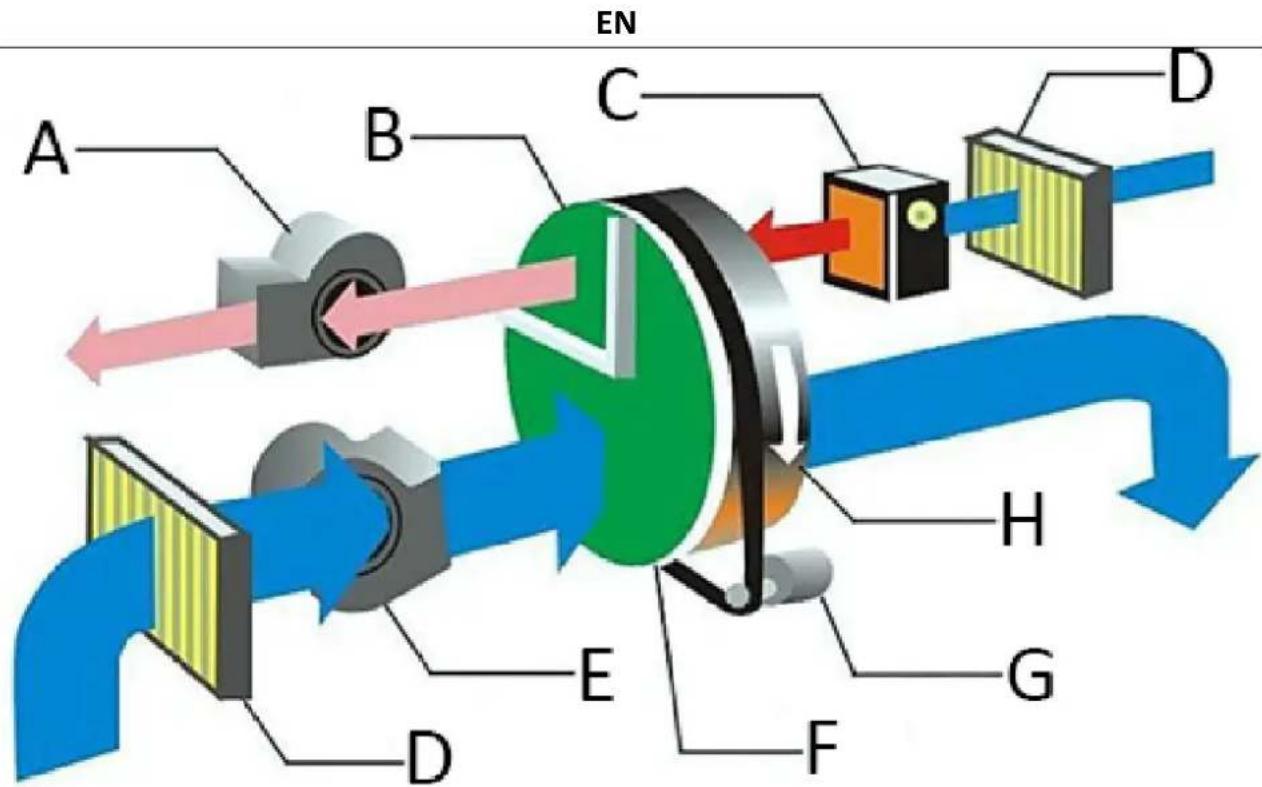
A Regeneration blower
B Regeneration recovery sector
C Bleeder heater
D Filter
E Processing fan
F Processing sector
G Driver motor
H Desiccant wheel
III. Product Installation
3.1 Shipment and Storage
To ensure the quality and reliability of the dehumidification machine, each unit is thoroughly inspected before delivery. If the machine needs to be stored for a period of time before installation, the following precautions should be observed:
①Do not dismantle the transportation packaging when the machine is shipped from the factory..
② Ensure the machine is placed in a manner that avoids any physical damage.
③The machine must be stored in a covered area to protect it from dust, frost, and rain.
3.2 Product Inspections
Remove the transportation packaging from the machine and inspect the product to ensure it was not damaged during transportation. If any damage is detected, please contact the equipment manufacturer immediately. If the piping connected to the dehumidification machine has already been installed, check whether the pipe layout is appropriate. If the environment or installation conditions are unsatisfactory, please reach out to the manufacturer for assistance.
3.3 Warning
- Warning! All electrical connections must be performed by professionals in accordance with local regulations. Ensure that the machine is connected to the correct voltage and frequency as specified on the machine's nameplate.
- Warning! The power supply switch should only be used for emergency shutdowns. When the machine stops, the regeneration blower also stops. If the regeneration heater accumulates heat, it may cause damage to components similar to the heater.
- Warning! The dehumidifier is designed for a specific air processing volume and should not be directly connected to an air conditioning system. Improper adjustment of the treated air and regenerated air volumes can lead to equipment failure.
3.4 Handling Equipment
Each module of the dehumidification machine weighs 15 kg, so it is essential to use a lifting device to prevent injury to personnel and damage to the machine. Handle the dehumidification machine with care. A crane or forklift can be used to move the machine. When using a crane, select appropriate lifting points that do not come into contact with the motor, control system, or exposed pipe fittings to avoid damaging the machine. Forklift and crane holes are located in the lower part of each module for this purpose.
3.5 Safety Placement
his dehumidifier is designed for indoor installation, and it is crucial to maintain adequate and compact service space for cleaning and maintenance. To prevent internal condensation, the dehumidifier should not be exposed to environments where the temperature is lower than the dew point of the processing air. If the machine must be installed outdoors, appropriate protective measures should be taken to prevent rainwater or snow from entering the unit.
3.6 Foundation Setting
The dehumidification machine must be installed on a horizontal surface or platform that can support the machine's weight. A special foundation is not necessary if the maximum load capacity is not exceeded. After installing the dehumidifier, verify that it is level. If the unit is required to be fixed setting, the installation hole shall be prefabricated on the steel of the unit.
3.7 Air Duct Connection
The processing air and regenerated air ducts should adhere to the recommended values specified in ISO 7807. The installation of pipe fittings for ducts and elbow flanges should not exceed 20mm in length. When installing the connected pipes for the dehumidifier's inlet and outlet, please consider the following recommendations:
- Minimize the length of the pipe as much as possible to reduce static pressure loss in the air system.
- Minimize the length of the pipe as much as possible to reduce static pressure loss in the air system.
- The air duct should be insulated to prevent the air flow temperature within the pipeline from dropping below the outside air's dew point temperature. This helps avoid exposing the outer wall of the pipe to condensation, which could lead to corrosion and energy loss.
- Pipes connected directly to the dehumidifier unit should be fully supported to minimize the load and pressure caused by the weight and operation of the pipeline.
- Ensure that the design and installation of the pipes do not restrict operation or maintenance access.
- To reduce the transmission of noise and vibration along the pipe, consider installing a high-quality, strong, airtight flexible connection at the regeneration outlet.
- An air valve must be installed on the outlet pipes of both the processing air and regenerated air.
- The total resistance of the piping on both the treatment side and the regeneration side should not exceed the capacity provided by the fan in the unit.
- If air is being drawn into the dehumidifier unit, ensure the inlet is positioned sufficiently high above the ground to prevent the intake of dust and debris. The inlet should be placed as far away as possible from sources of pollution such as energy waste, steam, and harmful gases. To prevent wet air from humidifying treated air, the outdoor inlet for treated air should be at least 2 meters away from the wet air outlet. Additionally, the piping design should consider protection against the intrusion of rainwater and snow.
- In the wet air duct of the regeneration system, where air has a high moisture content and condensation can easily form on the inner walls of the pipe, the horizontal pipe should be installed with a downward slope away from the dehumidification unit. A condensate drain should be placed at the lowest point of the pipeline to prevent water accumulation. Wet air ducts must be insulated to prevent corrosion and water accumulation if the air dew point temperature inside the pipe is higher than the external air temperature.
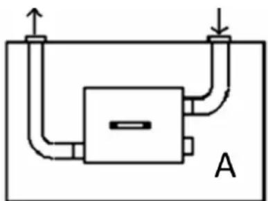
IV. Installation Instruction
natural_image
Pure schematic diagram of a mechanical or fluidic component with no text, numbers, or symbolsA
Dehumidification space
When the dehumidifier is placed indoors, the pipes for the regenerated air inlet and outlet must be connected to the outside. The processing air outlet should be directed to distribute air within the dehumidification room. The processing air inlet does not require a connected pipe.
V. Product Operation
The standard control of the dehumidifier has been configured internally, and additional programs are controlled and connected according to the user's requirements. The operation is straightforward, but the machine should be operated by a qualified professional. Before using the dehumidifier, please read the manual and all related instructions carefully
- Warning! Please read the instruction carefully before use, we shall not be liable for any loss caused by failure to follow the instructions.
- Warning! If the electrical control system fails, please ensure the main power supply is disconnected before performing any checks or maintenance. We shall not be liable for any loss resulting from unauthorized modifications to the circuit or related settings without proper knowledge or certainty.
- Warning! We shall not be liable for any loss resulting from unauthorized changes made by the user to the control circuit, control procedures, system parameters, or due to improper operation.
Power Switch with 3 positions:
- "O": Off mode, all parts will stop working.
- "MAN": Manual - device will continuously dehumidify till it is manually turned off.
- "AUTO": The device will automatically pause when the set humidity level is reached. If the relative humidity (RH) level rises above the set RH level, the machine will resume operation..
In operation mode, when the switch is turned on (either in "MAN" or "AUT" position), the blowers, wheel, and heater will run simultaneously. The ammeter will display the current drawn by the reactivation heater once it stabilizes, and the timer will start accumulating the machine's working time.
When the switch is in the “MAN” position, the dehumidifier fan wheel and the heater will run continuously, and the humidistat light will glow.
The machine uses the humidity controller to control the dehumidifier on/off. The humidity controller is placed in the dehumidifying area and the humidity scale is adjusted to the required humidity. When the environmental humidity is higher than the setting humidity, the machine turns on and when the environmental humidity is lower than the setting humidity, the machine turns off. The machine has its own control logic to control over temperature and limit current.
VI. Product Maintenance
6.1 Brief Introduction
The dehumidifier can run for a long time, and it requires minimal maintenance. It is beneficial for the long-term good operation of the unit to maintain the dehumidifier. The frequency of maintenance depends on the operating condition and installation environment of the unit. If the treated air is high in dust, the relative maintenance needs to be more frequent.
- Warning! There is high voltage inside the dehumidifier. Ensure that the power is completely cut off before performing any maintenance work.
- Warning! There are high-temperature areas inside the dehumidifier. Ensure that any maintenance work is performed only after the unit and the connected pipes have cooled down.
- Warning! The adjustment, maintenance, and repair of the unit should only be performed by a qualified technician. It is important that anyone involved is aware of the high temperature and high-pressure present inside the dehumidifier.
6.2 Inspection and Maintain Procedures
The procedures for checking and maintaining the routine parts of the unit are listed in the table. This may not include details about external components related to the machine. If necessary, please refer to additional relevant information provided by the equipment manufacturer.
EN
| Parts | Inspection and maintain procedures | |
| Half a month | 12 months | |
| Process Air and Regenerative Air Filters | Clean the filter box; replace if dirty. | Clean the filter box; replace if dirty. |
| Process air and regenerative air fans | Check whether there is mechanical damage, clean the casing of motor and fan as required | Dust and debris in the cooling groove on the surface of the motor housing must be cleaned, check the block terminal of the motor to ensure the wiring is not loose, check whether there is any damage to the impeller of the fan. If there are any signs of corrosion, please act immediately.Check the air volume and adjust the air valve as required, please refer to the commissioning section in the manual. |
| Wheel drive motor assembly | Check whether the driving belt is damaged and whether the installation is appropriate. | Check the wiring of the motor to ensure it is not loose. Check whether the block terminal of the motor is damaged and overheat. |
| Electrical control box and wiring | Check whether the components and wiring in the electrical cabinet is damaged and overheat. Make sure there is no loose connection | Inspect the components and wiring in the electrical cabinet for any signs of damage or overheating. During normal operation, if a component is always active or never activates, move or reset it several times regularly to engage its coil and contacts. Ensure all connections are secure, and clean any dust and debris from all parts. Clean dust and debris in the heat sink of the electric cabinet. |
| Regenerative heater and rear heater | Clean dust and debris in the bottom and surface of the heater. | Check all piping, wiring and control parts are loose or not. If it is loose, fasten it. Clean dust and debris in the bottom and surface of the heater. |
| Desiccant wheel | Check whether there is overheat and block or not. Clean dust in the surface of wheel | Check whether there is overheat and block or not. Clean dust in the surface of wheel. |
| Hermetical seal | Check whether there is damage or shift. If there is wear or damage, replace it. | Check whether there is damage or shift. If there is wear or damage, replace it. |
| The connection of unit and air duct | Check whether the air is leakage or not, and whether the connection of unit and air duct is | Check for air leaks and ensure that the connection between the unit and the air duct is secure. Additionally, inspect for any dust buildup and check for any signs of damage |
VII. Trouble shooting
7.1 Trouble Removal Procedure
If the unit fails, please consult the failure analysis and corresponding solutions provided below before contacting the equipment supplier, as the issue may be easy to troubleshoot. Note that this guide may not cover external components related to the machine. If needed, refer to additional relevant information provided by the equipment manufacturer
| Troubles | Possible cause | Measures to troubleshoot |
| Machine shuts down | Power supply faultSwitch selection is not selected to startThe circuit interrupter of supply lead trips offConnection faults and switch jumps off | Check the power supply of the machineSelect to the correct startChange the circuit interrupter Check the circuit of wiring |
| The wheels not running | The rotor motor is stuck | Remove obstacle |
| Regenerative air fan not running | The state switch is on AUTO | The state switch is on MAN |
| Heat pipe not working | Fuse burn down | Replace fuse |
| Unit not working | Power supply in trouble Humidity controller setup goes wrongInternal overheating | Overhaul circuit Change humidity settingDissipate heat inside the machine quickly |
| Dehumidification reduced | Regenerative heating capacity is not enough Wheel drive system failureThe humidity controller is not working properly. | Check the working conditions of the heater。Check the driving belt and driving motorCheck the parameters of the humidity controller |

natural_image
Exterior view of a rectangular electronic device with black ports and a central hub (no visible text or symbols)natural_image
Pure schematic diagram of a mechanical or fluidic system with no text, numbers, or symbolsnatural_image
Exterior view of a metallic industrial device with black ports and mounting holes (no text or symbols visible)natural_image
Pure schematic diagram of a mechanical or fluidic system with no text, numbers, or symbolsnatural_image
Exterior view of a metallic industrial device with black ports and mounting feet (no visible text or symbols)natural_image
Pure schematic diagram of a mechanical or fluidic system with no text, numbers, or symbolsnatural_image
Exterior view of a metallic industrial device with black ports and mounting holes (no visible text or symbols)natural_image
Pure schematic diagram of a mechanical or fluidic system with no text, numbers, or symbolsnatural_image
Exterior view of a metallic industrial device with black ports and mounting holes (no text or symbols visible)natural_image
Pure schematic diagram of a mechanical or fluidic component with no text, numbers, or symbolsnatural_image
Exterior view of a rectangular electronic device with black ports and a central hub (no visible text or symbols)A Regeneráló fúvóka
natural_image
Pure schematic diagram of a mechanical or fluidic system with no text, numbers, or symbolsA Páramentesítő tér
natural_image
Exterior view of a rectangular electronic device with black ports and a central hub (no visible text or symbols)natural_image
Pure schematic diagram of a mechanical or fluidic system with no text, numbers, or symbolsA Affugtningsrum
natural_image
Exterior view of a metallic industrial device with black ports and mounting feet (no visible text or symbols)natural_image
Pure schematic diagram of a mechanical or fluidic component with no text, numbers, or symbols7.1 Vianpoistomenettely
natural_image
Exterior view of a rectangular industrial device with black ports and a central hub (no visible text or symbols)natural_image
Pure schematic diagram of a mechanical or fluidic component with no text, numbers, or symbolsnatural_image
Exterior view of a rectangular industrial or laboratory device with black ports and a central hub (no visible text or symbols)natural_image
Pure schematic diagram of a mechanical or fluidic system with no text, numbers, or symbolsA Avfuktingsplass
natural_image
Exterior view of a metallic industrial device with black ports and mounting holes (no text or symbols visible)natural_image
Pure schematic diagram of a mechanical or fluidic component with no text, numbers, or symbolsnatural_image
Exterior view of a rectangular industrial device with black ports and a central hub (no visible text or symbols)natural_image
Pure schematic diagram of a mechanical or fluidic system with no text, numbers, or symbolsnatural_image
Exterior view of a metallic industrial device with black ports and mounting feet (no visible text or symbols)II. Predstavenie produktu
2.1 Stručný úvod
natural_image
Pure schematic diagram of a mechanical or fluidic system with no text, numbers, or symbolsA Priestor na odvlhčovanie
natural_image
Pure schematic diagram of a mechanical or fluidic component with no text, numbers, or symbolsnatural_image
Exterior view of a rectangular industrial device with black ports and a central hub (no visible text or symbols)natural_image
Pure schematic diagram of a mechanical or fluidic system with no text, numbers, or symbolsnatural_image
Exterior view of a metallic industrial device with black ports and mounting feet (no visible text or symbols)II. Predstavljanje proizvoda
2.1 Kratak uvod
natural_image
Pure schematic diagram of a mechanical or fluidic system with no text, numbers, or symbolsA Prostor za odvlaživanje
natural_image
Exterior view of a metallic industrial device with black ports and a central hub (no visible text or symbols)natural_image
Pure schematic diagram of a mechanical or fluidic component with no text, numbers, or symbolsA Sausinimo erdvė
natural_image
Exterior view of a rectangular electronic device with black ports and a central hub (no visible text or symbols)II. Introducere de produs
natural_image
Pure schematic diagram of a mechanical or fluidic system with no text, numbers, or symbolsnatural_image
Exterior view of a metallic industrial device with black ports and mounting feet (no visible text or symbols)natural_image
Pure schematic diagram of a mechanical or fluidic system with no text, numbers, or symbolsA
Prostor za razvlaževanje
For the disposal of the device please consider and act according to the national and local rules and regulations.
CONTACT
expondo Polska sp. z o.o. sp. k.