TP-CC 10 T - Saw EINHELL - Free user manual and instructions
Find the device manual for free TP-CC 10 T EINHELL in PDF.

| Product type | Table circular saw |
| Brand | Einhell |
| Model | TP-CC 10 T |
| Category | Saw |
| Rated power S1 | 1800 W |
| Rated power S6 (25%) | 2000 W |
| Supply voltage | 220-240 V ~ 50 Hz |
| No-load speed | 4200 rpm |
| Blade diameter | 254 mm |
| Blade bore | 30 mm |
| Blade thickness | 2.9 mm |
| Number of teeth | 24 |
| Max. cutting height (90°) | 85 mm |
| Max. cutting height (45°) | 55 mm |
| Blade tilt range | 0° to 45° (continuous) |
| Cross-cut angle | -60° to +60° |
| Dust extraction connection | Ø 36 mm |
| Weight | approx. 22.2 kg |
| Protection class | II |
| Safety devices | Protective cover, riving knife, push stick, overload switch |
| Sound pressure level | 95.2 dB(A) |
| Sound power level | 108.2 dB(A) |
| Maintenance | Regular cleaning, replacement of carbon brushes by a specialist |
| Wear parts | V-belt, carbon brushes, table insert, push stick |
| Repairability | Einhell after-sales service, spare parts available |
Frequently Asked Questions - TP-CC 10 T EINHELL
User questions about TP-CC 10 T EINHELL
0 question about this device. Answer the ones you know or ask your own.
Ask a new question about this device
Download the instructions for your Saw in PDF format for free! Find your manual TP-CC 10 T - EINHELL and take your electronic device back in hand. On this page are published all the documents necessary for the use of your device. TP-CC 10 T by EINHELL.
USER MANUAL TP-CC 10 T EINHELL
GB Original operating instructions Bench-type circular saw
natural_image
Exterior view of a rectangular electronic device with wheels and a central vent (no text or symbols visible)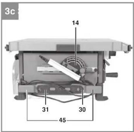
natural_image
Cross-sectional diagram of a printer or scanner with internal components and a paper feed, labeled with number 2 (no text or symbols beyond label)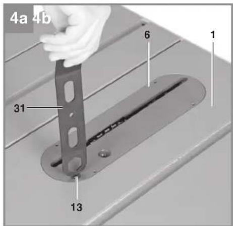
natural_image
Hand placing a smartphone into a device with a label pointing to it (no text or symbols on the device itself)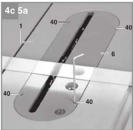
natural_image
Mechanical gear assembly diagram with no visible text or symbols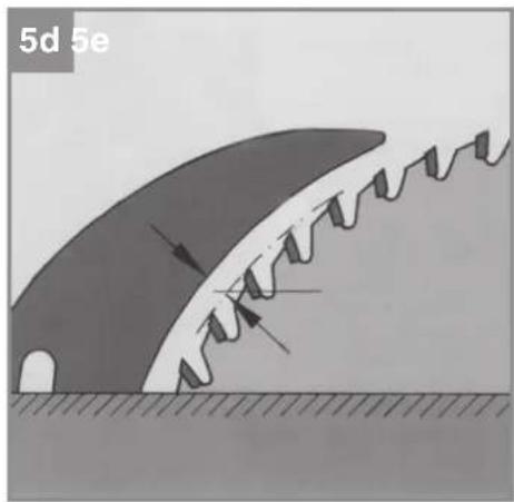
natural_image
Diagram of a mechanical or structural component with directional arrows indicating motion, no readable text or symbols present.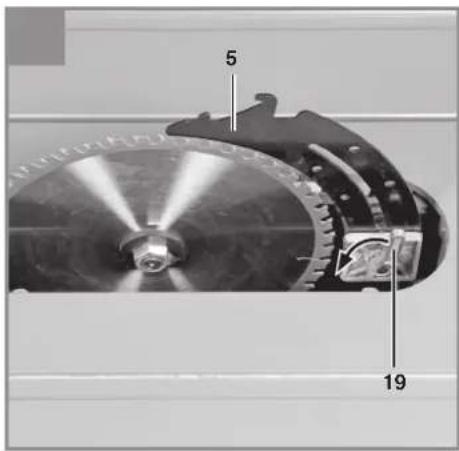
natural_image
Close-up of a mechanical assembly with visible gears and components (no text or symbols)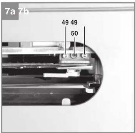
natural_image
Cross-sectional view of a mechanical device with labeled parts (no readable text or symbols)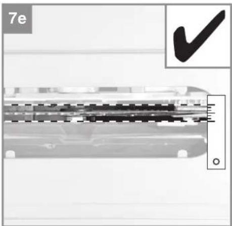
natural_image
Close-up of a mechanical component with a checkmark and scale bar, no readable text or symbols present.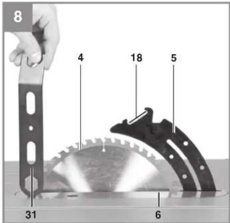
natural_image
Person using a tool to cut a transparent plastic component, no visible text or symbols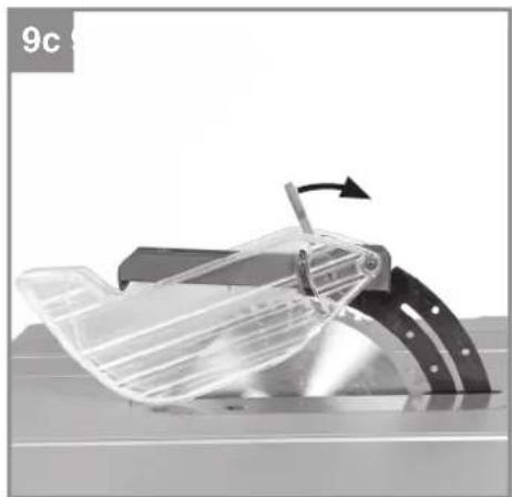
natural_image
Mechanical component with a rotating arrow indicating motion (no text or symbols visible)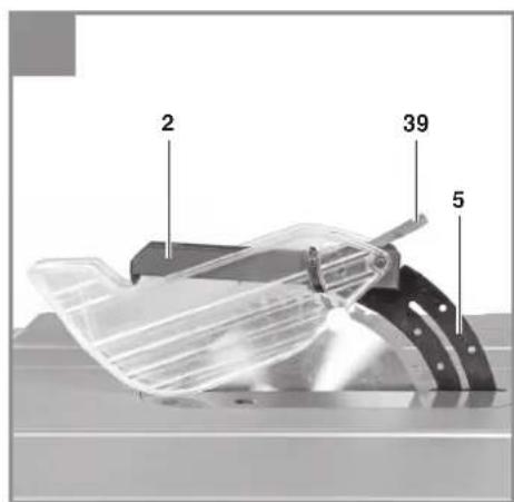
-7-
natural_image
Close-up of a mechanical device with a dial and measurement scale (no visible text or symbols)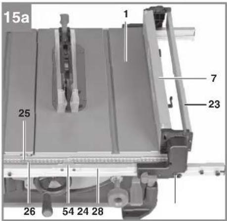

natural_image
Mechanical assembly diagram showing a component with a 60-degree angle indicator and a curved arrow pointing to a specific part (no text or symbols present)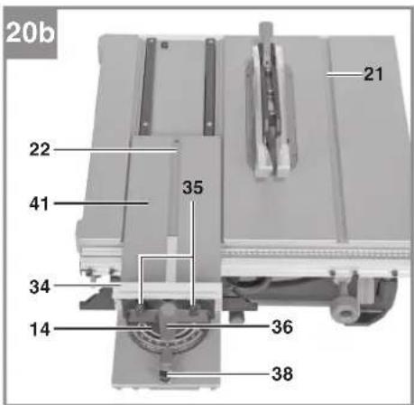

natural_image
Close-up of a mechanical device with metal components and a scale ruler (no visible text or symbols)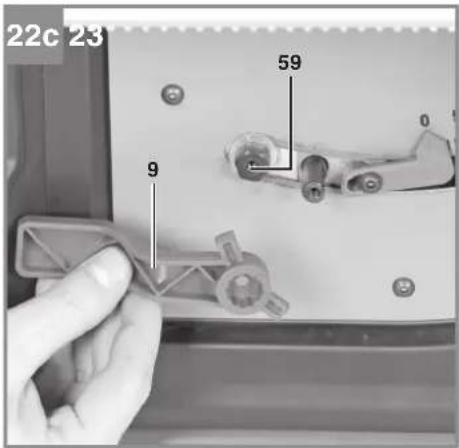
natural_image
Mechanical assembly with a flatbed base and metal frame (no visible text or symbols)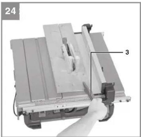
natural_image
Close-up of a mechanical cutting machine with a hand operating it, labeled with number 24 and numbered 3 (no text or symbols on the machine itself)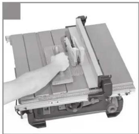
natural_image
Close-up of a hand using a lathe machine to cut metal sheets (no text or symbols visible)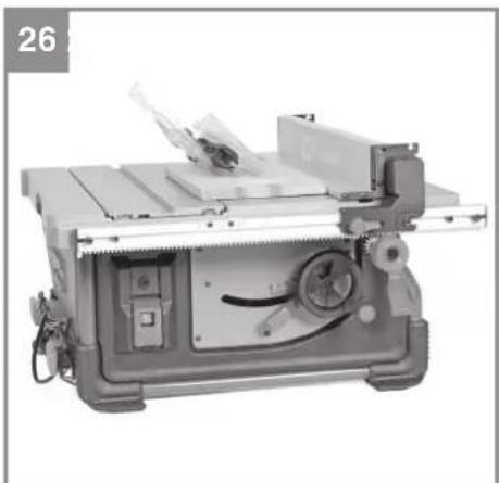
natural_image
Industrial machine with metal tray and control panel (no visible text or symbols)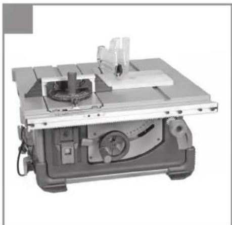
natural_image
Industrial machine with workbench and cutting tool (no visible text or symbols)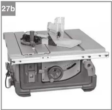
natural_image
Industrial machine with workbench and metal components (no visible text or symbols)
natural_image
Mechanical assembly with a cutting machine and workpiece (no visible text or symbols)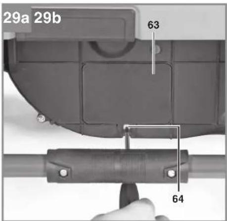
natural_image
Mechanical component diagram showing a curved housing with a labeled part (4), no readable text or symbols present.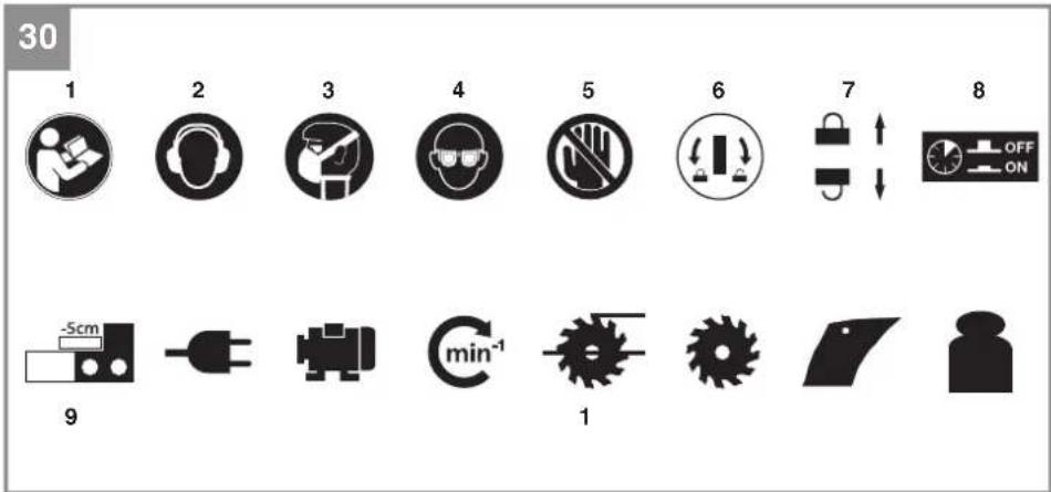
3
D
Gefahr!
When using the equipment, a few safety precautions must be observed to avoid injuries and damage. Please read the complete operating instructions and safety regulations with due care. Keep this manual in a safe place, so that the information is available at all times. If you give the equipment to any other person, hand over these operating instructions and safety regulations as well. We cannot accept any liability for damage or accidents which arise due to a failure to follow these instructions and the safety instructions.
Explanation of the symbols used (see Fig. 30)
- Danger! - Read the operating instructions to reduce the risk of injury.
- Caution! Wear ear-muffs. The impact of noise can cause damage to hearing.
- Caution! Wear a breathing mask. Dust which is injurious to health can be generated when working on wood and other materials. Never use the device to work on any materials containing asbestos!
- Caution! Wear safety goggles. Sparks generated during working or splinters, chips and dust emitted by the device can cause loss of sight.
- Caution! Risk of injury! Do not reach into the running saw blade.
- Using the supplied ring wrench, turn the disk clockwise to release the table insert. Turn the disk counter-clockwise to secure the table insert against falling out.
- To adjust the blade angle, swing the locking lever downwards. To lock the blade angle, swing the locking lever upwards.
- Press in the overload cut-out in order to release the On/Off switch again.
- When you fold the stop rail over the saw table for narrow cutting widths, this will reduce the actual cutting width by 5 cm compared to the cutting width reading.
- Conditions of the mains connection
- Power rating
- Speed
- Cutting height at 90° and 45° blade angle
- Blade dimensions
- Thickness of the splitter
- Weight
1. Safety regulations
The corresponding safety information can be found in the enclosed booklet.
WARNING!
Read all safety warnings, instructions, illustrations and specifications provided with this power tool. Failure to follow all instructions listed below may result in electric shock, fire and/or serious injury.
Save all warnings and instructions for future reference.
2. Layout and items supplied
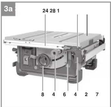
2.1 Layout (Fig. 1-29)
- Saw table
- Blade guard
- Push stick
- Blade
- Splitter
- Table insert
- Parallel stop
- Hand wheel
- Locking lever for blade angle
- Hole in the machine frame
- On/Off switch
- Overload switch
- Rotary disk
- Cross stop
- Screw for blade
- Extractor adapter
- Extractor socket
- Recess on the splitter
- Fastening lever
- Fastening plate
- Slot in the saw table
- Slot in the slide
- Foldable stop rail
- Guide rail for parallel stop
- Main scale
- Width extension scale
- Locking bolt for the parallel stop
- Guide screw for the parallel stop
- Retaining screw for the parallel stop
- 24 mm ring wrench
- 20/24 mm combination wrench
- 0° adjustment screw
- 45° adjustment screw
- Stop rail for the cross stop
- Thumb screw for the cross stop
- Locking screw for the cross stop
- Button cover for the emergency stop switch
GB
- Fastening screw for the cross stop
- Eccentric lever for the blade guard
- 2.5 mm socket head screw for the table insert
- Slide
- Clamping lever for the guide rail
- Threaded sleeve
- Nut
- Cable holder
- Rotary knob for the cutting width
- Rotary knob shaft
- Recessed head screw for the rotary knob
- 4 mm socket head screw for the splitter
- 2.5 mm grub screw for the splitter
- Cover for the self-locking nut
- Recessed head screw for the cover
- Self-locking nut
- Pointer for the parallel stop
- Angle scale
- Pointer for the blade angle
- 3 mm socket head screw for the hand wheel
- 3 mm socket head screw for the locking lever
- Hexagon screw
- Locking lever
- 0° eccentric plate
- 45° eccentric plate
- Cover for the suction channel
- Recessed head screw for the suction channel
• Bench-type circular saw
- Blade guard
- Push stick
- Parallel stop
Cross stop
- Extractor adapter
• 24 mm ring wrench
• 20/24 mm combination wrench
• Rotary knob for the cutting width
• Recessed head screw for the rotary knob
• Original Operating Instructions
• Safety Information
3. Proper use
The bench-type circular saw is designed for the slitting and cross-cutting (only with the cross stop) of all types of timber commensurate with the machine's size. The equipment is not to be used for cutting any type of round wood.
The equipment is to be used only for its prescribed purpose. Any other use is deemed to be a case of misuse. The user / operator and not the manufacturer will be liable for any damage or injuries of any kind caused as a result of this.
The equipment is to be operated only with suitable saw blades (saw blades made of HM or CV) It is prohibited to use any type of HSS saw blade and cutting-off wheel.
To use the equipment properly you must also observe the safety information, the assembly instructions and the operating instructions to be found in this manual.
All persons who use and service the equipment have to be acquainted with these operating instructions and must be informed about the equipment's potential hazards. It is also imperative to observe the accident prevention regulations in force in your area. The same applies for the general rules of health and safety at work.
The manufacturer will not be liable for any changes made to the equipment nor for any damage resulting from such changes. Even when the equipment is used as prescribed it is still impossible to eliminate certain residual risk factors.
The following hazards may arise in connection with the machine's construction and design:
- Contact with the saw blade in the uncovered saw zone.
- Reaching into the running saw blade (cut injuries).
GB
- Kick-back of workpieces and parts of workpieces.
- Saw blade fracturing.
- Catapulting of faulty carbide tips from the saw blade.
- Damage to hearing if essential ear-muffs are not used.
- Harmful emissions of wood dust when used in closed rooms.
4. Technical data
AC motor 220-240V \~ 50Hz
Power P ....S1 1800 W · S6 25% 2000 W
Idling speed n _n ....4200 rpm
Carbide saw blade .....∅ 254 x ∅ 30 x 2.9 mm
Number of teeth ..... 24
Cutting height max. 85 mm / 90°
..... 55 mm / 45°
Height adjustment .... infinite 0 - 85 mm
Tilting saw blade .... infinite 0° - 45°
Cross stop angle ....... infi nite -60° - 60°
Extractor connection .......Ø 36 mm
Weight approx. 22.2 kg
Protection class: Ⅱ回
Thickness of the splitter 2.3 mm
Operating mode S6 25%: Continuous operation with idling (cycle time 10 minutes). To ensure that the motor does not become excessively hot, it may only be operated for 25% of the cycle at the specified rating and must then be allowed to idle for 75% of the cycle.
Danger!
Noise
The noise emission values were measured in accordance with EN 62841.
Operation
L_pA sound pressure level ..... 95.2 dB (A)
K_dA uncertainty 3 dB (A)
L_wA sound power level ..... 108.2 dB (A)
K_WA uncertainty 3 dB (A)
Wear ear-muff s.
The impact of noise can cause damage to hearing.
The stated noise emission values were measured in accordance with a set of standardized criteria and can be used to compare one power tool with another.
The stated noise emission values can also be used to make an initial assessment of exposure.
Warning:
The noise emission levels may vary from the level specified during actual use, depending on the way in which the power tool is used, especially the type of workpiece it is used for.
Keep the noise emissions and vibrations to a minimum.
- Only use appliances which are in perfect working order.
• Service and clean the appliance regularly.
• Adapt your working style to suit the appliance.
• Do not overload the appliance. - Have the appliance serviced whenever necessary.
- Switch the appliance off when it is not in use.
Limit the operating time!
All stages of the operating cycle must be considered (for example, times in which the electric tools are switched off and times in which the tool is switched on but operates without load).
Caution!
Residual risks
Even if you use this electric power tool in accordance with instructions, certain residual risks cannot be rules out. The following hazards may arise in connection with the equipment's construction and layout:
-
Lung damage if no suitable protective dust mask is used.
-
Damage to hearing if no suitable ear protection is used.
5. Before starting the equipment
Before you connect the equipment to the mains supply make sure that the data on the rating plate are identical to the mains data.
GB
Warning!
Always pull the power plug before making adjustments to the equipment.
- Unpack the bench-type circular saw and check it for damage which may have occurred in transit.
- The machine has to be set up where it can stand firmly, e.g. on a work bench, or it must be bolted to a strong base.
- All covers and safety devices have to be properly fitted before the machine is switched on.
- It must be possible for the saw blade to run freely.
- When working with wood that has been processed before, watch out for foreign bodies such as nails or screws etc.
Before you actuate the On/Off switch, make sure that the saw blade is correctly fitted and that the machine's moving parts run smoothly.
6. Assembly
Danger! Pull out the power plug before carrying out any maintenance, resetting or assembly work on the bench-type circular saw.
6.1 Setting up the bench-type circular saw (Fig. 2)
- Danger! Make allowance for the weight of the machine and arrange for another person to help you if necessary!
- The bench-type circular saw must be stood on a level surface.
- To ensure that the saw stands securely we recommend that you fasten the bench-type circular saw on a firm substructure by the 4 holes (10) in the machine frame. Suitable fastening materials (screws, etc.) are available from your dealer.
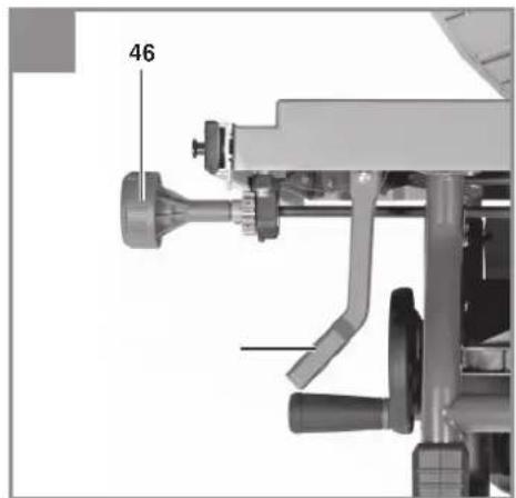
- Fit the rotary knob (46) on the shaft (47). Secure the rotary knob (46) with the recessed head screw (48).
- Fit the extractor adapter (16) on the extractor socket (17) at the back of the machine.
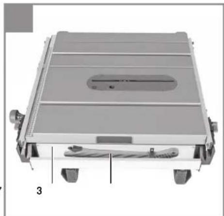
6.2 Transport setting (Fig. 3)
The bench-type circular saw is set at the factory for transport. For compact transport and for optimum storage, always fasten all the loose parts in the holders provided (see Fig. 3).
- Wind the power cable onto the cable holder (45).
- Position the cross stop (14) and the two wrenches (30, 31) on the left side of the machine.
- Fasten the push stick (3) on the parallel stop (7).
- Secure the parallel stop (7) to the guide rail (24) (see 6.9).
When you want to transport or store the machine it is also advisable to set it as compactly as possible and create a level surface with the saw table (1). To prevent parts projecting beyond the saw table (1) you must do the following:
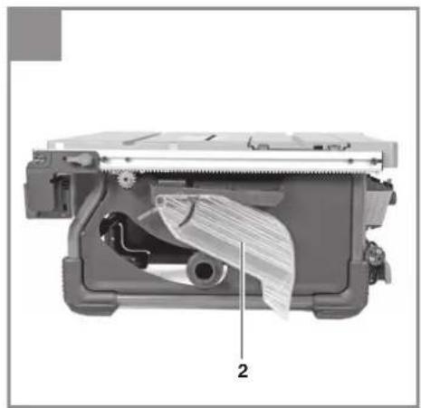
- Remove the blade guard (2), hang it on the holder at the back of the machine and fasten it in position. (see 6.6)
• Lower the splitter (5) into the transport setting. (see 6.4) - Use the hand wheel (8) to lower the blade so that the blade (4) and the splitter (5) are below the table surface.
- Use the clamping lever (42) to slacken the guide rail (24). Use the rotary knob (46) to move the guide rail (24) to the right until it is accessible from underneath.
- With the parallel stop (7) facing downwards, move it to the guide rail (24) and fasten the stop at the guide screws (28) on the outer right-hand side. (see 6.9)
- Move the guide rail (24) to the far left and fasten it with the clamping lever (42).
• To convert the saw from transport position to working position, proceed in reverse order.
6.3 Fitting/changing the table insert (Fig. 4, 8)
- To prevent a higher risk of injury, the table insert (6) must be replaced whenever it becomes worn or damaged.
• Take off the saw blade guard (2) (see 6.6). - Position the combination wrench (31) with the tip on the rotary disk (13). Use the wrench to turn the disk (13) clockwise in order to release the table insert.
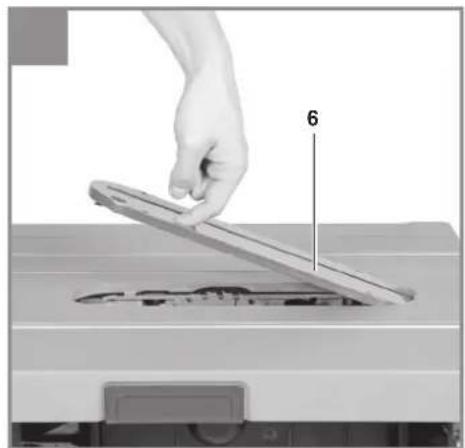
• Take out the worn table insert (6). - To fit the replacement table insert, proceed in reverse order.
- Warning! When the workpiece is moved in feeding direction, it must not be blocked by the table insert!
- The height of the table insert (6) relative to the saw table (1) is set at the factory. Check the setting on a regular basis with the help of an object with a straight edge (e.g. a ruler, an angle gauge, etc.).
- If necessary, the table insert (6) can be re-adjusted in height by means of socket head screws (40).
GB
- Warning! The support surface of the table insert (6) must not project at the front side!
- Warning! The support surface of the table insert (6) must not lie below the saw table (1) at the rear side!
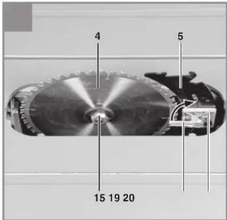
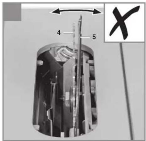
6.4 Moving the splitter into working position (Fig. 5, 6)
Warning! In the as-delivered state the splitter (5) is in transport position. For operation always fasten the splitter (5) in top position (working position) as described below.
- Using the hand wheel (8), set the blade (4) to maximum cutting depth, move it to 0° position and lock it in place.
- Remove the blade guard (2) and the table insert (6) (see 6.6, 6.3).
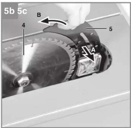
• Turn the fastening lever (19) upwards in order to slacken the splitter (5). - Press the splitter (5) sideways in order to release the locked transport position. (see Fig. 5b, arrow A)
- When the splitter (5) is pressed sideways, guide the splitter (5) upwards into working position. (see Fig. 5b, arrow B)
- Danger! The splitter (5) must latch in the top position! Once the splitter (5) has latched in the top position, the fastening plate (20) will press the splitter (5) inwards again.
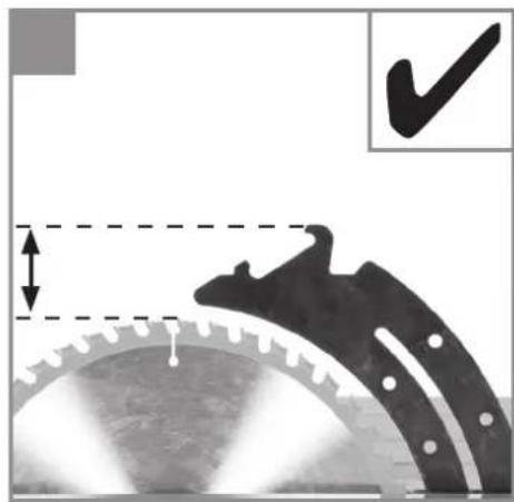
Before you clamp the splitter, make sure that the gap between the blade (4) and the splitter (5) equals 3 to 8 mm. (see Fig. 5d) - Fasten the splitter (5) using the fastening lever (19).
- Warning! The splitter (5) must be fastened securely.
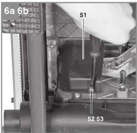
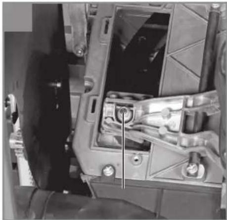
- Important! If the tension of the fastening lever (19) is insufficient, you can make adjustments by tightening the self-locking nut (53). To get access to the self-locking nut (53), undo the recessed head screw (52) and remove the cover (51).
- Refit the table insert (6) and the blade guard (2). (see 6.6, 6.3)
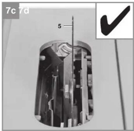
6.5 Checking the splitter position and making necessary adjustments (Fig. 7)
The position of the splitter (5) relative to the blade (4) is set at the factory. To ensure safe operation at all times, check the setting before beginning to work.
The splitter (5) must be positioned centrally on an imaginary extended plane behind the blade (4) so that it is impossible for the cut material to become jammed.
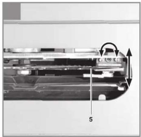
- If necessary, the splitter (5) can be readjusted in all directions relative to the cutting plane.
• Undo the two socket head screws (49). - By turning the grub screw (50) in or out you can adjust the splitter (5) over the complete cutting height parallel to the cutting plane.
- As long as the socket head screws (49) have been slackened, you can freely align the splitter (5) transversely to the cutting plan.
- Important! Place an object with a straight edge (e.g. a ruler) on both sides of the blade (4). Use this arrangement to make sure that the splitter (5) does not project beyond the cutting plane of the blade (4).
- Tighten the socket head screws (49) again and check the setting.
- Caution! Tighten the two socket head screws (49) with the same tension.
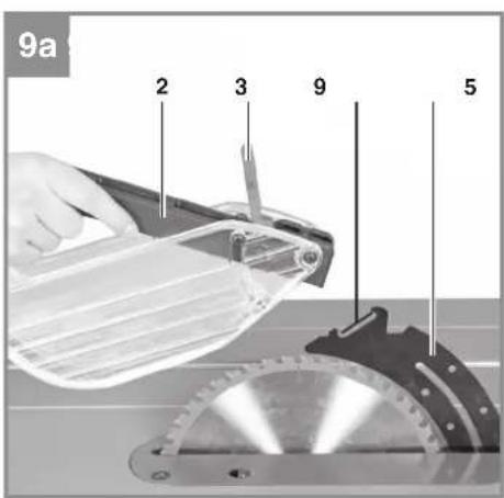
6.6 Fitting/changing the blade guard (Fig. 9)
- Danger! Before operation, always fasten the blade guard (2) to the splitter (5).
• Make sure that the eccentric lever (39) is open, i.e. is pointed in the direction of the front edge of the blade guard (2). - Guide the blade guard (2) centrally onto the splitter (5) and first hang the rear pin in the recess (18) on the splitter.
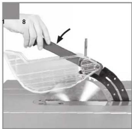
- Then tilt the blade guard (2) downwards until the front pin is also resting in the recess (18) on the splitter.
- Tension the blade guard (2) by pressing the eccentric lever (39) to the rear, i.e. towards the rear side of the machine.
- Warning! The saw blade guard (2) must always descend onto the workpiece automatically under its own weight.
- After mounting the saw blade guard (2), check that it works correctly by raising it and letting it go.
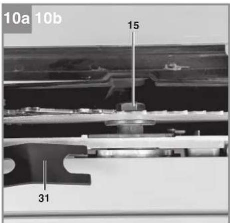
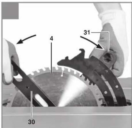
6.7 Fitting/changing the blade (Fig. 10)
- Before changing the saw blade: Pull out the power plug!
- Wear work gloves to prevent injury when changing the blade!
- Remove the saw blade guard and the table insert (see 6.6, 6.3).
- Release the fastening lever (19) in order to provide access to the work area.
- Undo the screw (15) with one wrench (30) on the screw (15) itself and a second wrench (31) on the motor shaft to apply counter-pressure.
GB
- Caution! Turn the screw (15) in the direction of rotation of the blade.
- Remove the outer flange and the old blade (4) from the inner flange.
- Clean the blade flange thoroughly before fitting the new blade.
- Fit and fasten the new blade (4) in reverse order.
- Warning! Note the running direction. The cutting angle of the teeth must point in running direction, i.e. forwards (see the arrow on the blade guard).
- Secure the fastening lever (19) again, then mount and adjust the splitter, the table insert and the blade guard (see 6.5, 6.3, 6.6).
- Check that all safety devices are in good working order before you begin working with the saw again.
- Warning! Every time you change the blade, check that the blade guard (2) opens and closes again in accordance with requirements. Also check that the blade (4) spins freely in the saw blade guard (2).
- Warning! Every time that you change the blade, check to see that it spins freely in the table insert (6) in both perpendicular and 45° angle settings.
- Warning! A worn or damaged table insert (6) must be replaced immediately (see 6.3).
- Warning! The work to change and align the blade (4) must be carried out correctly.
6.8 Connection for dust extraction (Fig. 11)
A connection option for dust extraction is provided at the extractor adapter (16) on the housing. For example, you can connect a wet & dry vac (not included with this product) to the extractor adapter (16).
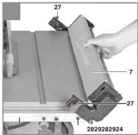
6.9 Fitting/removing the parallel stop (Fig. 12)
- Open the two locking bolts (27) on the front and back sides of the parallel stop (7) by turning the locking bolts (27) by 90° upwards.
- To fit the parallel stop (7), move the position of the guide screws (28) outwards as far as possible so that you can mount the parallel stop (7) alongside the saw table (1).
- Clean any chips, dust or other dirt off the support surfaces on the parallel stop and off the guide rail (24).
-
With the parallel stop (7) tilted by approx. 45°, guide it by the recess onto the guide screws (28).
-
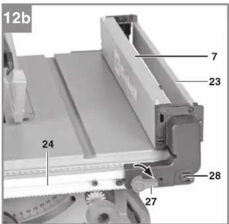
Tilt the parallel stop (7) downwards. Make sure that the parallel stop (7) and the retaining screw (29) engage with each other. The mount of the parallel stop (7) should rest over the entire width firmly on the guide rail (24) and is not allowed to wobble.
- Secure the parallel stop (7) by closing the two locking bolts (27).
- To remove the parallel stop (7) again, proceed in reverse order.
7. Operation
7.1 On/Off switch (Fig. 1, 13 / Item 11)
- To turn the saw on, press the green button „I“. Wait for the blade to reach its maximum speed of rotation before commencing with the cut.
- The red button "0" is covered by the switch cover (37). To switch off the saw, press the switch cover (37).
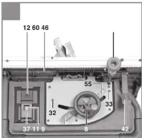
The motor of this equipment is protected against overload by an overload switch (12). If the rated current is exceeded, the overload switch (12) will shut down the equipment.
- Let the equipment cool down for several minutes.
• Press the overload switch (12). - Press the green button „I“ to switch on the equipment.
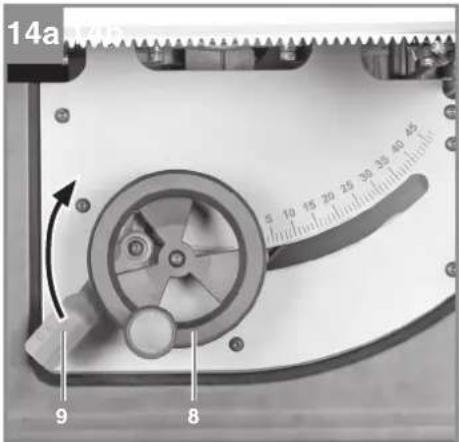
7.2 Cutting depth (Fig. 1, 14)
Turn the hand wheel (8) to set the blade (4) to the required cutting depth.
Warning! To reduce the risk of coming into contact with the blade (4), always adjust the cutting depth of the blade to the thickness of the workpiece.
Rule of thumb: The blade (4) should be moved in and out only as far as necessary for the tips of the blade teeth to project visibly beyond the workpiece.
Turn counter-clockwise:
Smaller cutting depth
Turn clockwise:
Larger cutting depth
GB
7.3 Parallel stop
The parallel stop (7) must be used when making longitudinal cuts in wooden workpieces. When you mount or adjust the parallel stop (7), make sure that it is aligned parallel to the blade (4). For longitudinal cuts, take the cross stop (14) off the saw table (1) and place it in the holder provided.
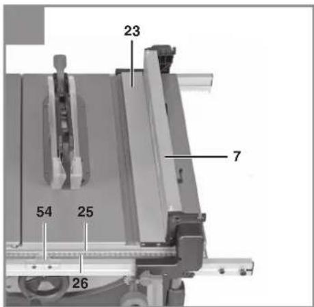
7.3.1 Selecting the parallel stop position (Fig. 15)
You can fasten the parallel stop (7) in 3 different positions according to your requirements and purposes. How to fit the parallel stop (7) on the guide rail (24) is described in 6.9.
- For smaller cutting widths you must fasten the parallel stop (7) at the guide screws on the inner right-hand side (28) (see Fig. 15a).
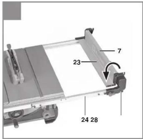
- To be able to use the maximum possible cutting width, you must fasten the parallel stop (7) at the guide screws on the outer right-hand side (28) (see Fig. 15b). Important! In this position you can machine only workpieces with a width of 11 cm and more.
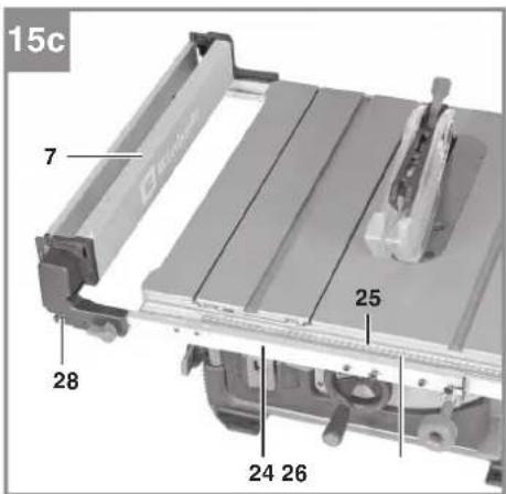
- The parallel stop (7) can also be fitted on the left-hand side of the blade (4) (see Fig. 15c). Important! In this case the cutting width cannot be read off the scale (25 or 26) but must be set using a suitable measuring tool (e.g. a folding rule).
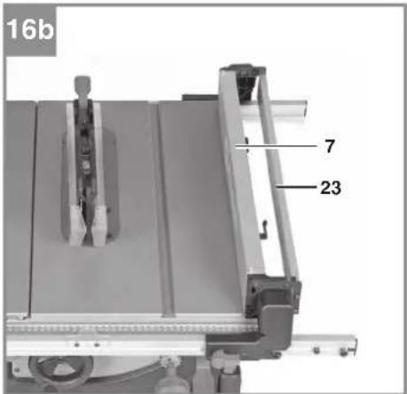
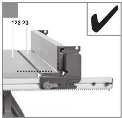
7.3.2 Setting the foldable stop rail (Fig. 16, 17)
The foldable stop rail (23) performs two different functions according to the application. It can serve either to reduce the stop height of the parallel stop (7) for narrow workpieces or to provide a supporting surface for large cutting widths.
Stop height (Fig. 16)
- Warning! The stop height must always be set such that the workpiece can be guided as well as possible past the blade (4).
- The parallel stop (7) supplied with the product must be used together with the downward folded stop rail (23) when you perform longitudinal cuts on narrow wooden workpieces (see Fig. 16a).
- To make longitudinal cuts in wider wooden workpieces of max. 33 cm you can use the parallel stop (7) also with the upward folded stop rail (23) (see Fig. 16b).
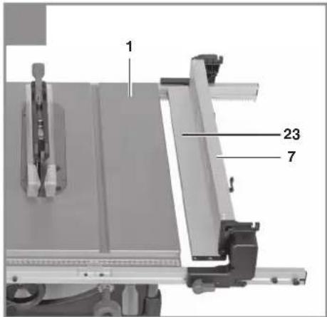
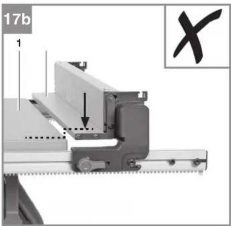
Supporting surface (Fig. 17)
- Warning! For cutting widths bigger than 33 cm you must fold the stop rail (23) fully downwards so that the supporting surface of the foldable stop rail (23) has the same height as the surface of the saw table (1).
- Especially with big cutting widths make sure that the workpiece lies safely on the saw table (1) and on the foldable stop rail (23) and that it cannot become jammed.
7.3.3 Cutting width (Fig. 15-18)
• Fit the parallel stop (7) on the guide rail (24) as described in 6.9.
- When the parallel stop (7) is fitted at the guide screws on the inner right-hand side (28), read the set cutting width on the main scale (25).
- Important! When you fold the stop rail (23) over the saw table (1) for narrow cutting widths, this will reduce the actual cutting width by 5 cm compared to the cutting width reading.
- When the parallel stop (7) is fitted at the guide screws on the outer right-hand side (28), read the set cutting width on the width extension scale (26).
• Pull the clamping lever (42) up in order to slacken the guide rail (24).
- The cutting width is infinitely adjustable by turning the rotary knob (46).
- Use the rotary knob (46) to move the guide rail (24) until the pointer (54) points to the desired dimension setting on the scale (25 or 26).
- Lock the set cutting width by pressing the clamping lever (42) down.
- Important! If the set cutting width deviates from the actual cutting width, you can readjust the pointer (54). The pointer (54) is screwed via slots to the guide rail (24).
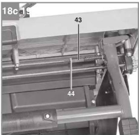
7.3.4 Readjusting the clamping force (Fig. 18)
Danger! Always ensure that the parallel stop (7) is fastened securely on the guide rail (24) and that the guide rail (24) cannot slip.
- The clamping force of the clamping lever (42) can be readjusted if necessary.
- To do so, slacken the nut (44) and screw the threaded sleeve (43) out or in as far as required to reach the desired clamping force.
- Finally, fasten the threaded sleeve (43) again with the nut (44).
GB
7.4 Cross cuts
To make cross cuts, remove the parallel stop (7) from the saw table (1).
The cross stop (14) must be used when making cross cuts in wooden workpieces.
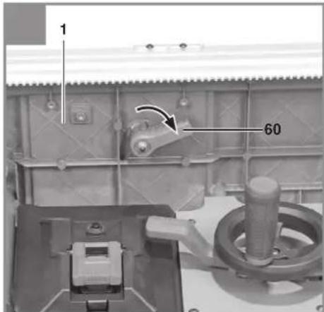
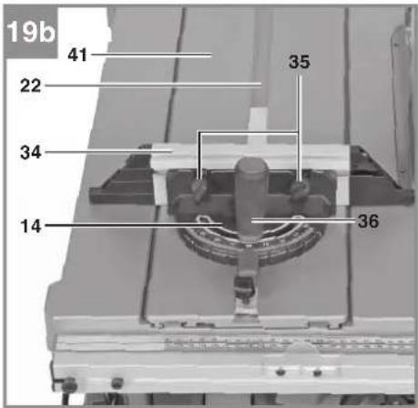
7.4.1 Cross cutting with a secured slide (Fig. 19)
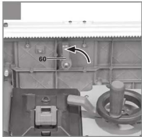
- Make sure that the slide (41) is securely locked to the saw table (1). The locking lever (60) on the underside of the saw table (1) should point transversely to the cutting direction (see Fig. 19a).
- The cross stop (14) can be used both to the left of the blade (4), i.e. in the slot (22) of the slide (41), or to the right of the blade (4), i.e. in the slot (21) of the saw table (1).
• Slacken the locking screw (36). - Turn the stop rail (34) until the arrow points to the angle required.
- The cross stop (14) has latching positions at 90°, 75°, 60°, 45° and 30°, where the stop rail (34) latches audibly in place. As soon as the stop rail has latched in place, the setting must be secured with the locking screw (36).
- If you need different angle settings, use only the thumb screw (35) to secure the stop rail (34).
• Re-tighten the locking screw (36). - Check the gap between the stop rail (34) and the saw blade (4).
- Warning! Do not push the stop rail (34) too far toward the blade (4). The distance between the stop rail (34) and the blade (4) should be approx. 2 cm.
- If necessary, slacken the two thumb screws (35) and adjust the stop rail (34).
• Re-tighten the thumb screws (35).
7.4.2 Cross cutting with a moving slide (Fig. 20)
- Slide the cross stop into the slot (22) of the slide (41).
- Use the fastening screw (38) to secure the cross stop (14) according to the cutting width at the slide (41).
- Unlock the slide (41) by turning the locking lever (60) through 90° in cutting direction (see Fig. 20a).
- Warning! The locking lever (60) must be fully open so that the slide (41) cannot latch in place unintentionally during the cutting operation.
- The angle on the cross stop (14) and the gap between the stop rail (34) and the blade (4) must be set as described in 7.4.1.
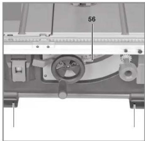
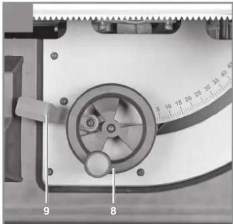
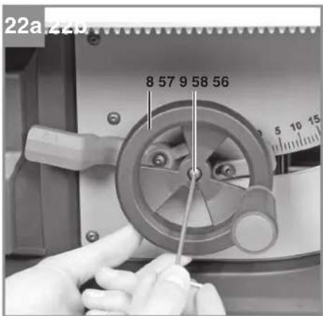
7.5 Setting the blade angle (Fig. 13, 14)
- Slacken the locking lever (9) by swinging it down.
- Adjust the blade angle by pushing the hand wheel (8) until the pointer (56) is aligned with the desired dimension setting on the angle scale (55).
- Secure the angle by tightening the locking lever (9).
- Important! If the value deviates from the angle scale (55), you can readjust the pointer (56). The pointer (56) is screwed in place via a slot on the machine. (see Fig. 22b)
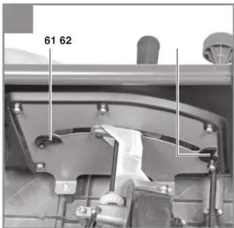
Readjusting the end stop for the blade angle (Fig. 13, 21)
If required, the end stop for the blade angle setting can be readjusted at 0^ and at 45^ .
• To do so, slacken the adjustment screw for 0^ (32) or the adjustment screw for 45^ (33).
- Use a suitable measuring tool (e.g. a 90° angle or an angle gauge) to set the angle to 90° or 45°.
- Lock the blade angle with the locking lever (9).
- Turn the eccentric plate for 0° (61) or for 45° (62) on the inside of the machine until it rests against the inner blade bracket.
- Secure the setting by tightening the adjustment screw (32 or 33).
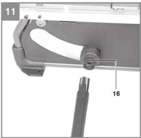
Readjusting the clamping force of the locking lever (Fig. 22)
- Remove the hand wheel (8). To do so, undo the socket head screw (57) and pull the hand wheel (8) outwards and off.
- Undo the socket head screw (58) and pull the locking lever (9) off the hexagon screw (59).
• Mount the locking lever (9) on the hexagon screw (59) one latching position further on. - Secure the locking lever (9) with the socket head screw (58).
- Mount the hand wheel (8) again and secure it with the socket head screw (57).
GB
8. Operation
Warning!
• After every new adjustment we recommend you to make a trial cut in order to check the new settings.
- After switching on the saw, wait for the blade to reach its maximum speed of rotation before commencing with the cut.
• Take extra care when starting the cut!
- Never use the equipment without the suction function.
- Regularly check and clean the suction channels.
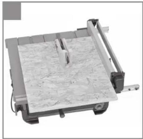
8.1 Making longitudinal cuts (Figure 23)
Longitudinal cutting (also known as slitting) is when you use the saw to cut along the grain of the wood. Press one edge of the workpiece against the parallel stop (7) while the fl at side lies on the saw table (1). The guard hood (2) must always be lowered over the workpiece.
When you make a longitudinal cut, never adopt a working position that is in line with the cutting direction.
- Set the parallel stop (7) in accordance with the workpiece height and the desired width. (See 7.3.)
- Switch on the saw.
- Place your hands (with fingers closed) flat on the workpiece and push the workpiece along the parallel stop (7) and into the blade (4).
- Guide at the side with your left or right hand (depending on the position of the parallel stop) only as far as the front edge of the guard hood.
- Always push the workpiece through to the end of the splitter (5).
• The offcut piece remains on the saw table (1) until the blade (4) is back in its position of rest. - Secure long workpieces against falling off at the end of the cut (e.g. with a roller stand etc.).
8.1.1 Cutting narrow workpieces (Fig. 24)
Be sure to use a push stick (3) when making longitudinal cuts in workpieces smaller than 150 mm in width. A push block is supplied with the saw! Replace a worn or damaged push stick immediately. Keep the push stick (3) always ready to hand in the holder provided.
8.1.2 Cutting extremely narrow workpieces (Fig. 25)
- Be sure to use a push block when making longitudinal cuts in very narrow workpieces with a width of 50 mm and less.
- The low guide face of the parallel stop is best used in this case.
- There is no push block supplied with the saw! (Available from your specialist dealer). Replace the push block without delay when it becomes worn.
8.2 Making angular cuts with a tilted blade (Fig. 13, 26)
Bevel cuts must always be used using the parallel stop (7).
If you tilt the saw blade (4) to the left when making angular cuts, position the parallel stop (7) on the right-hand side of the saw blade (4). Guide the workpiece between the saw blade (4) and the parallel stop (7).
- Set the blade (4) to the desired angle. (See 7.5.)
- Set the parallel stop (7) in accordance with the workpiece width and height (see 7.3)
- Carry out the cut in accordance with the workpiece width (see 8.1.1., 8.1.2.)
8.3 Making cross cuts (Fig. 27, 28)
- Push the cross stop (14) into the appropriate slot (21 or 22) and set the slide (41), the required angle and the stop rail (34) (see 7.4).
- Press the workpiece firmly against the cross stop (14).
- Switch on the saw.
- Push the cross stop (14) and the workpiece toward the blade in order to make the cut.
- Warning!
Always hold the guided part of the workpiece. Never hold the part which is to be cut off. - Push the cross stop (14) forward until the workpiece is cut all the way through.
- Switch off the saw again. Do not remove the offcut until the blade has stopped rotating.
9. Transport
Only ever transport the machine by lifting it by the saw table. Never use the safety devices such as the saw blade guard and stop rails for handling or transporting purposes.
GB
10. Replacing the power cable
Danger!
If the power cable for this equipment is damaged, it must be replaced by the manufacturer or its after-sales service or similarly trained personnel to avoid danger.
11. Cleaning, maintenance and ordering of spare parts
Danger!
Always pull out the mains power plug before starting any cleaning work.
11.1 Cleaning
- Keep all safety devices, air vents and the motor housing free of dirt and dust as far as possible. Wipe the equipment with a clean cloth or blow it with compressed air at low pressure.
• We recommend that you clean the device immediately each time you have finished using it. - Clean the equipment regularly with a moist cloth and some soft soap. Do not use cleaning agents or solvents; these could attack the plastic parts of the equipment. Ensure that no water can seep into the device. The ingress of water into an electric tool increases the risk of an electric shock.
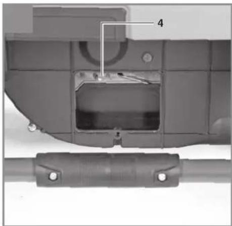
- Check the suction channels regularly. To clean the suction channels and remove any blockages from them, undo the recessed head screw (64) and remove the cover (63) (see Fig. 29). Caution! The blade is freely accessible; wear protective gloves.
11.2 Carbon brushes
In case of excessive sparking, have the carbon brushes checked only by a qualified electrician. Danger! The carbon brushes should not be replaced by anyone but a qualified electrician.
11.3 Maintenance
There are no parts inside the equipment which require additional maintenance.
11.4 Ordering spare parts and accessories Please provide the following information when ordering spare parts:
• Type of unit
• Article number of the unit
• ID number of the unit
- Spare part number of the required spare part For our latest prices and information please go to www.Einhell-Service.com

Tip! For good results we recommend high-quality accessories from !kwb www.kwb.eu welcome@kwb.eu
12. Disposal and recycling
The equipment is supplied in packaging to prevent it from being damaged in transit. The raw materials in this packaging can be reused or recycled. The equipment and its accessories are made of various types of material, such as metal and plastic. Never place defective equipment in your household refuse. The equipment should be taken to a suitable collection center for proper disposal. If you do not know the whereabouts of such a collection point, you should ask in your local council offices.
13. Storage
Store the equipment and accessories in a dark and dry place at above freezing temperature. The ideal storage temperature is between 5 and 30 °C. Store the electric tool in its original packaging.
GB

For EU countries only
Never place any electric power tools in your household refuse.
To comply with European Directive 2012/19/EC concerning old electric and electronic equipment and its implementation in national laws, old electric power tools have to be separated from other waste and disposed of in an environment-friendly fashion, e.g. by taking to a recycling depot.
Recycling alternative to the return request:
As an alternative to returning the equipment to the manufacturer, the owner of the electrical equipment must make sure that the equipment is properly disposed of if he no longer wants to keep the equipment. The old equipment can be returned to a suitable collection point that will dispose of the equipment in accordance with the national recycling and waste disposal regulations. This does not apply to any accessories or aids without electrical components supplied with the old equipment.
Please note that batteries and lamps (e.g. light bulbs) must be removed from the tool before it is disposed of.
The reprinting or reproduction by any other means, in whole or in part, of documentation and papers accompanying products is permitted only with the express consent of the Einhell Germany AG.
Subject to technical changes
GB
Service information
We have competent service partners in all countries named on the guarantee certificate whose contact details can also be found on the guarantee certificate. These partners will help you with all service requests such as repairs, spare and wearing part orders or the purchase of consumables.
Please note that the following parts of this product are subject to normal or natural wear and that the following parts are therefore also required for use as consumables.
| Category Example | |
| Wear parts* V-belt, carbon brushes, table insert, push stick | |
| Consumables* Saw blade | |
| Missing parts | |
* Not necessarily included in the scope of delivery!
In the effect of defects or faults, please register the problem on the internet at www.Einhell-Service.com. Please ensure that you provide a precise description of the problem and answer the following questions in all cases:
• Did the equipment work at all or was it defective from the beginning?
• Did you notice anything (symptom or defect) prior to the failure?
• What malfunction does the equipment have in your opinion (main symptom)?
Describe this malfunction.
GB
Warranty certificate
Dear Customer,
All of our products undergo strict quality checks to ensure that they reach you in perfect condition. In the unlikely event that this equipment develops a fault, please contact our service department at the address shown on this guarantee card. You can also contact us by telephone using the service number shown. Please note the following terms under which guarantee claims can be made:
-
These guarantee terms apply solely to consumers, i.e. natural persons, who do not want to use this product in connection with either their commercial or other self-employed activities. These guarantee terms regulate additional guarantee services which the undermentioned manufacturer promises to buyers of its new products in addition to their statutory rights of guarantee. Your statutory rights of guarantee are not affected by this guarantee. Our guarantee is free of charge to you.
-
The guarantee services cover only defects due to material or manufacturing faults on the new product which you have bought in the European Union from the undermentioned manufacturer and are limited to either the rectification of said defects or the replacement of the product, whichever we prefer. Please note that only equipment under the brand name "Professional" has been designed for use in commercial, trade or professional applications. For all other products the guarantee is invalidated if the equipment is used within the guarantee period in commercial, trade or industrial applications or for other equivalent activities.
-
Our guarantee does not cover:
-
Damage to the equipment caused by failure to comply with the installation/assembly instructions or by unprofessional installation; damage caused by failure to comply with the operating instructions (e.g. connection to the wrong mains voltage or current type); damage caused by failure to comply with the maintenance and safety regulations; damage caused by exposing the equipment to abnormal environmental conditions; damage resulting from poor care and maintenance.
- Damage to the equipment caused by misuse or incorrect applications (e.g. overloading the equipment or using non-approved attachments or accessories); damage caused by foreign bodies (e.g. sand, stones, dust, ....) getting inside the equipment. Damage in transit; damage caused by force or external influences (e.g. by dropping the equipment).
-
Damage to the equipment or parts of the equipment which is owed to use-related, normal or otherwise natural wear. For example, batteries and battery packs are manufactured with a cycle limit for design-related reasons. Wear is negatively influenced in particular by load demands and charging speeds as well as exposure to heat, cold, vibration and impact.
-
The guarantee is valid for a period of 2 years starting from the purchase date of the equipment. Guarantee claims must be submitted before the end of the guarantee period and within two weeks of the defect being noticed. No guarantee claims will be accepted after the end of the guarantee period. The original guarantee period remains applicable to the equipment even if repairs are carried out or parts are replaced. In such cases, the work performed or parts fitted will not result in an extension of the guarantee period, and no new guarantee will become active for the work performed or for any replacement parts fitted. This also applies if on-site service is used.
-
To assert your guarantee claim, register the defective equipment at: www.Einhell-Service.com. You will need to provide proof of purchase of the new item of equipment. Equipment returned without such proof or without a rating plate are excluded from the guarantee services because of the lack of traceability. If the defect is covered by our guarantee, then either the item in question will be repaired immediately and returned to you or we will send you a new replacement.
-
If you have taken the equipment with you to a different EU country than where you bought it, we will arrange for a local service partner to provide the guarantee services. If you take the equipment outside the EU, the guarantee will not apply.
Of course, we are also happy to offer a chargeable repair service for any defects which are not covered or no longer covered by the scope of this guarantee. To take advantage of this service, please send the equipment to our service address. We draw attention to the restrictions of this guarantee concerning wear parts, consumables and missing parts as presented in the service information included in this operating manual.
Warrantor/ Service:
Einhell UK Ltd, Unit 10, 1st Floor, Champion's Business Park, Arrowe Brook Road, Upton, Wirral, CH49 0UQ
F
Danger!
6.2 Position de transport (fi gure 3)
Negotovost K_WA 3 dB (A)
Subject to change without notice
Archive-File/Record: NAPR025429
Documents registrar: Korbinian Wasmeier
Wiesenweg 22, D-94405 Landau/Isar
^1 SH Bench-type circular saw - SA Circle-tirale à tabre - I Saga circione de banco - DK/AN Bourdinsauf - S Bondoirkelasseag - CZ Stolni kotoulové pila - SK Stolni kotoulové pila - NL Tafereinkalzag - E Stora circular de masa - FIN Poysdakinkel - SLO Navitine kristne raga - H Asstellkirtlurser - RO Ferdatu circular sur minus GA - Pernola molyse (yoyou) - Perra circular de banda. HR/HN Stolni kruzhna pila - PS Stona kruzhna testora - PL Przecharka do dreveu - TR Targathil Deire Testore - RUS Dusikovine nama co storou - EE Lausoklassag - LG Gelda npragdis - LT Stalinis disknis pjukos - BG Kirrupur harestorn - UKH Nasthalla drickova nila - MK Kirrupurnera nila co seasa - NO Bondoirkelasseag - IS Boró-hylog

Declaration of conformity
We, Einhell UK Ltd
Champions Business Park, First Floor Unit 10, Arrowe Brook Rd, Upton, Wirral CH49 0AB, United Kingdom
declare the conformity to UK standards and legislation was assessed for:
Table Saw TP-CC 10 T (Einhell)
| UK legislation | |
| Simple Pressure Vessels (Safety) Regulation | Electromagnetic Compatibility Regulation |
| Electrical Equipment (Safety) Regulation | Measuring Instruments Regulation |
| Radio Equipment Regulation | Pressure Equipment (Safety) Regulation |
| Personal Protective Equipment Regulation | |
| The Ecodesign for Energy-Related Products and Energy Information Regulation | |
| The Restriction of the Use of Certain Hazardous Substances in Electrical and Electronic Equipment Regulation | |
| Noise Emission in the Environment by Equipment for use Outdoors Regulation | |
| Annex V | |
| Annex VI | |
| Noise:measured L_WA = dB (A); guaranteed L_WA = dB (A)P = kW; L/∅ = cmApproved Body: | |
| Supply of Machinery (Safety) Regulation | |
| Annex IV | |
| Approved Body: TÜV SÜD Product Service GmbH Zertifizierstellen (NB 0123); Ridlerstraße 65; 80339 München; Germany Certifi cate No.: M6A 024192 2054 Rev. 00 | |
Standard References: EN 62841-1; EN IEC 62841-3-1; EN IEC 55014-1; EN IEC 55014-2; EN IEC 61000-3-2; EN 61000-3-3
Wirral, 2023.09.05

Archive-File/Record: NAPR025429
Article Number: 43.404.35 I.-No.: 21012
Subject to change without notice Wiesenweg 22, 94405 Landau/Isar, Germany
Documents registrar: Korbinian Wasmeier
EH 09/2023 (01)