
PerfectView RVS 535 - Rear Camera DOMETIC - Free user manual and instructions
Find the device manual for free PerfectView RVS 535 DOMETIC in PDF.

| Product Type | LCD monitor for rear view camera system |
| Brand | Dometic |
| Model | PerfectView RVS 535 (M55L or M75L monitor) |
| Screen size | 5 inches (12.7 cm) for M55L, 7 inches (17.8 cm) for M75L |
| Screen type | Color TFT LCD |
| Resolution | 385,000 pixels |
| Brightness | Approx. 350 cd/m² (M55L) / 400 cd/m² (M75L) |
| TV standard | PAL / NTSC (auto switch) |
| Operating voltage | 12 – 30 V (DC) |
| Max power | 10 W |
| Operating temperature | -20 °C to 70 °C |
| Storage temperature | -25 °C to 80 °C |
| Max humidity | 85% |
| Vibration resistance | 6 g |
| Dimensions (W x H x D) | 146 x 87 x 26 mm (M55L) / 190 x 110 x 26 mm (M75L) |
| Weight | 350 g (M55L) / 400 g (M75L) |
| Main functions | Display of cameras (up to 3), switching between sources, image settings (brightness, contrast, color), automatic brightness dimmer, mirror function, control by reverse gear or turn signal |
| Maintenance and cleaning | Clean with a damp cloth; do not use sharp objects; disconnect before cleaning |
| Safety | Do not install in airbag deployment zone; secure mounting; do not open the monitor; do not immerse; observe electrical polarity |
| Delivery contents | Monitor, monitor bracket, bracket cover, connection cable, mounting hardware |
| Optional accessories | Infrared remote control, sun visor (ref. 9102200199, 9102200200/0201) |
| Intended use | Use in leisure vehicles; connection of cameras or other video sources |
| Warranty | Statutory warranty; contact local subsidiary or dealer |
| Certifications | E13 |
Frequently Asked Questions - PerfectView RVS 535 DOMETIC
User questions about PerfectView RVS 535 DOMETIC
0 question about this device. Answer the ones you know or ask your own.
Ask a new question about this device
Download the instructions for your Rear Camera in PDF format for free! Find your manual PerfectView RVS 535 - DOMETIC and take your electronic device back in hand. On this page are published all the documents necessary for the use of your device. PerfectView RVS 535 by DOMETIC.
USER MANUAL PerfectView RVS 535 DOMETIC
natural_image
Line drawing of a rectangular electronic device with labeled ports (WRECO) and internal slots, no text or symbols beyond brandingPerfectView M55L, M75L
DE 9 LCD-Monitor
Installation and Operating Manual
FR 37 Ecran LCD
We will be happy to provide you with further information about Dometic WAECO products. Please order our free catalogue with no obligation to buy on our homepage: www.dometic-waeco.com

natural_image
Technical line drawing of a mechanical component with no visible text or symbols2

natural_image
Line drawing of a multimeter with connected cables and probes (no text or symbols)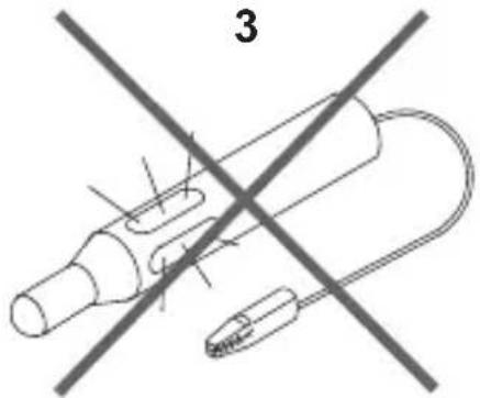
4
natural_image
Technical line drawing of a mechanical component with multiple slots and a circular end (no text or symbols)5

6
natural_image
Simple line drawing of a hammer with a triangular head and handle (no text or symbols)7

natural_image
Three cylindrical objects with diagonal striped patterns, no text or symbols present8
natural_image
Line drawing of a mechanical device with a cylindrical shaft and housing (no text or symbols)9
natural_image
Three different screwdriver tips shown in line drawings (no text or symbols)10
11

natural_image
Line drawing of a handheld device with a cylindrical body and handle (no text or symbols)121314
natural_image
Line drawing of a pliers with a coiled wire and circular end (no text or symbols)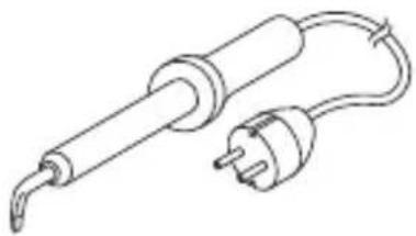
natural_image
Line drawing of a soldering iron with a terminal and power outlet (no text or symbols)
natural_image
Technical diagram showing a welding process with two intersecting lines and arrows indicating motion (no text or symbols)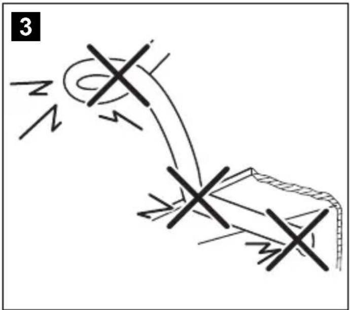
natural_image
Line drawing of a hand using a tool to cut a flatboard into a microwave oven with a diagonal line crossing (no text or symbols)
natural_image
Illustration of a person sitting in a chair with a steering wheel and a light bulb, no text or symbols present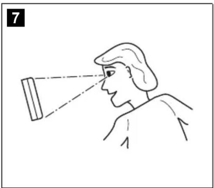
natural_image
Line drawing of a person observing through a projector (no text or symbols)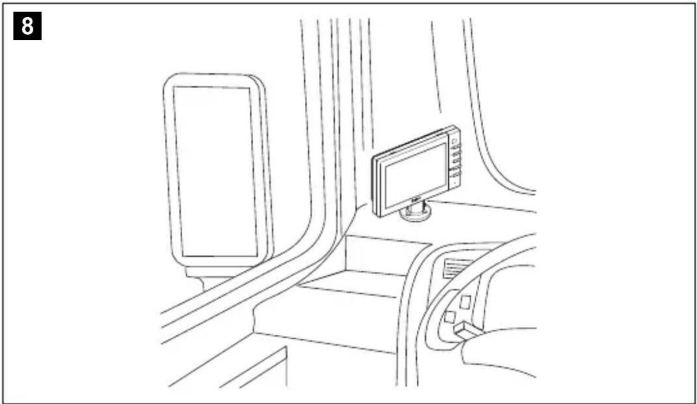
natural_image
Line drawing of a train interior showing a monitor mounted on the side and seat, with no visible text or symbols.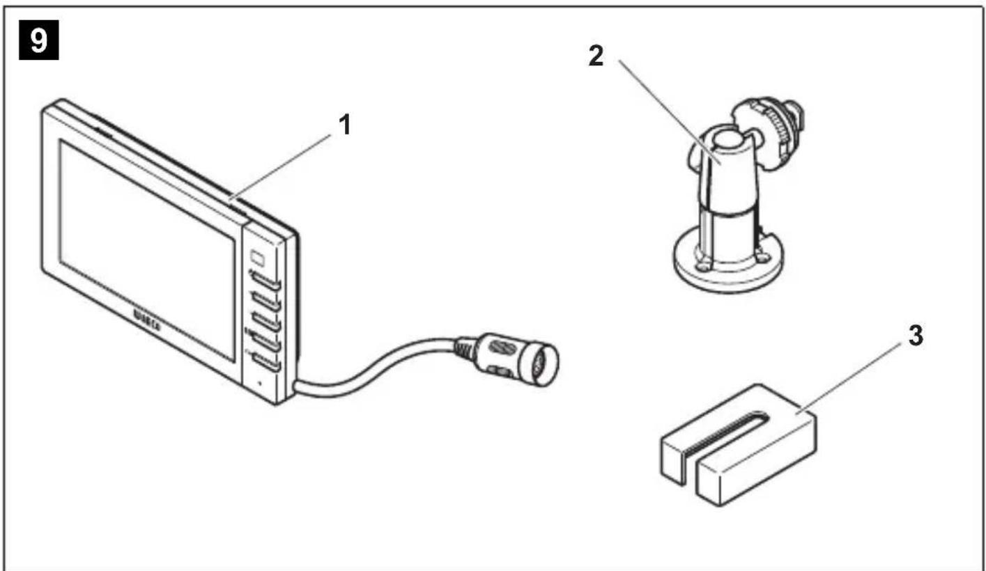
10

flowchart
graph TD
    A["1. Input"] --> B["2. Plug to a plug"]
    B --> C["3. Insert part of battery"]
    C --> D["4. Add plug into battery"]
    D --> E["5. Output"]
14
Please read this instruction manual carefully before installation and first use, and store it in a safe place. If you pass on the product to another person, hand over this instruction manual along with it.
Table of contents
1 Explanation of symbols 23
2 Safety and installation instructions.... 24
3 Scope of delivery 26
4 Accessories 26
5 Intended use 27
6 Technical description 27
7 Installing the LCD monitor 29
8 Using the LCD monitor.... 33
9 Cleaning and caring for the LCD monitor.... 35
10 Warranty.... 35
11 Disposal 35
12 Technical data 36
1 Explanation of symbols

CAUTION!
Safety instruction: Failure to observe this instruction can lead to injury.

NOTICE!
Failure to observe this instruction can cause material damage and impair the function of the product.

NOTE
Supplementary information for operating the product.
▶ Action: This symbol indicates that action is required on your part. The required action is described step-by-step.
√This symbol describes the result of an action.
Fig. 1 5, page 3: This refers to an element in an illustration. In this case, item 5 in figure 1 on page 3.
2 Safety and installation instructions
Please observe the safety instructions and stipulations issued by the vehicle manufacturer and service workshops.
The manufacturer accepts no liability for damage in the following cases:
● Faulty assembly or connection
● Damage to the product resulting from mechanical influences and excess voltage
● Alterations to the product without express permission from the manufacturer
● Use for purposes other than those described in the operating manual

NOTICE! Beware of damage
- To prevent the risk of short circuits, always disconnect the negative terminal of the vehicle's electrical system before working on it.
If the vehicle has an additional battery, its negative terminal should also be disconnected. - Inadequate supply cable connections could result in short circuits, causing:
- Cable fires
- The airbag being triggered
– Damage to electronic control equipment
– Electrical malfunctions (indicators, brake light, horn, ignition, lights)
Therefore, please observe the following instructions:
- When working on the following cables, only use insulated cable terminals, plugs and flat sockets:
- 30 (direct supply from positive battery terminal)
- 15 (connected positive terminal, behind the battery)
- 31 (return cable from the battery, earth)
- 58 (reversing light)
Do not use porcelain wire connectors.
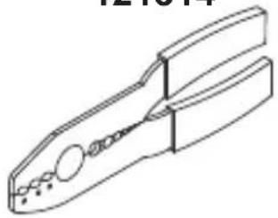
- Use a crimping tool (fig. 1 12, page 3) to connect the cables.
- Screw the cable when connecting cable 31 (earth)
- Use a crimping tool (fig. 1 12, page 3) to connect the cables. - Screw the cable when connecting cable 31 (earth)
- Screw on the cable using a cable terminal and serrated washer to one of the vehicle's earth bolts or
- Screw the cable to the bodywork using a cable terminal and a self-tapping screw
- Screw on the cable using a cable terminal and serrated washer to one of the vehicle's earth bolts or - Screw the cable to the bodywork using a cable terminal and a self-tapping screw
Make sure there is a good earth connection.
If you disconnect the negative terminal of the battery, all data stored in the volatile memories will be lost.
● The following data must be reset, depending on the vehicle equipment options:
- Radio code
- Vehicle clock
- Timer
- On-board computer
- Seat position
You can find instructions for making these settings in the operating manual.
Observe the following installation instructions:

CAUTION!
- Secure the monitor in such a way that it cannot become loose under any circumstances (sudden braking, accidents) and cause injuries to the occupants of the vehicle.
- Do not attach the monitor in the air bag deployment path, as this could cause injury if the airbags are triggered.
Observe the following instructions when working with electrical parts:
- When testing the voltage in electrical cables, only use a diode test lamp (fig. 1 1, page 3) or a voltmeter (fig. 1 2, page 3).
Test lamps with a bulb (fig. 1 3, page 3) consume voltages which are too high and can damage the vehicle's electronic system. - When routing the electrical connections, ensure that:
– They are not kinked or twisted
– They do not rub on edges
- They are not laid in sharp-edged ducts without protection (fig. 3, page 4).
● Insulate all connections.
- Secure the cables against mechanical wear by using cable binders or insulating tape, for example on existing cables.
Observe the following instructions when handling the LCD monitor:

CAUTION!
- People (including children) whose physical, sensory or mental capacities or whose lack of experience or knowledge prevent them from using this product safely should not use it without the supervision or instruction of a responsible person.
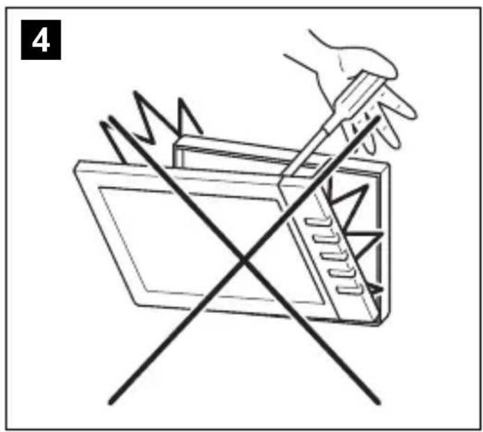
- Do not open the monitor (fig. 4, page 4).
- Do not submerge the monitor in water (fig. 5, page 4); the monitor is not waterproof.
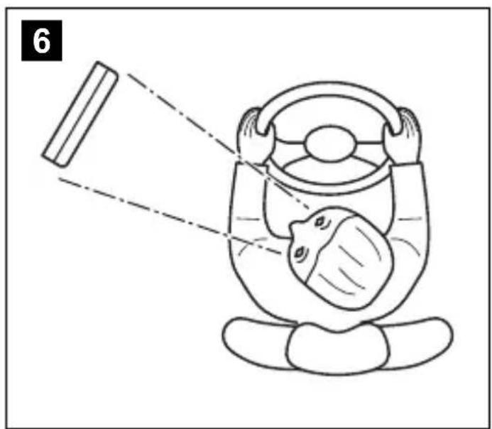
- The monitor must not impair your vision when driving (fig. 8, page 5).
- Do not operate the monitor with wet hands.
- Do not operate the monitor if the housing has been damaged.

NOTICE!
- Connect it to the correct voltage.
- Do not use the monitor in areas which
– Are subjected to direct sunlight,
- Are subject to strong temperature fluctuations,
– Have high levels of humidity,
- Are poorly ventilated,
- Are dusty or oily.
- Do not press against the LCD display.
- Do not drop the monitor.
- If you use the monitor in vehicles, the vehicle should be running during operation to prevent the vehicle battery from discharging.
● The picture quality can be impaired in the vicinity of electromagnetic fields. For this reason do not mount the monitor near loudspeakers.
3 Scope of delivery
No. in
fig. 9,
page 5
Quantity Description
Item no.
M55L M75L
1 1 Monitor 9102100056 9102100057
2 1 Monitor bracket 9102200193
3 1 Monitor bracket cover 9102200194
- 1 Connection cable 9102200195
-- Fastening material
4 Accessories
Available as accessories (not included in the scope of delivery):
| Description | Item no. |
| IR remote control | 9102200199 |
| Sun visor for M55L | 9102200200 |
| Sun visor for M75L | 9102200201 |
5 Intended use
The LCD monitors PerfectView M55L (item no. 9102100056) and M75L (item no. 9102100057) are monitors which are primarily intended for use in vehicles. They can be used together with cameras (e.g. a reversing video system) or other video sources.
The LCD monitors are designed for use in all vehicles.
The LCD monitor are designed for leisure use.
6 Technical description
6.1 Function description
The LCD monitor can be connected to cameras (e.g. reversing video systems) or other video sources (e.g. DVD players). It is possible to switch back and forth between video sources.
The monitor features control cables which allow the cameras to be activated automatically.
It can operate up to three cameras.
It can be used with a RAM mount.
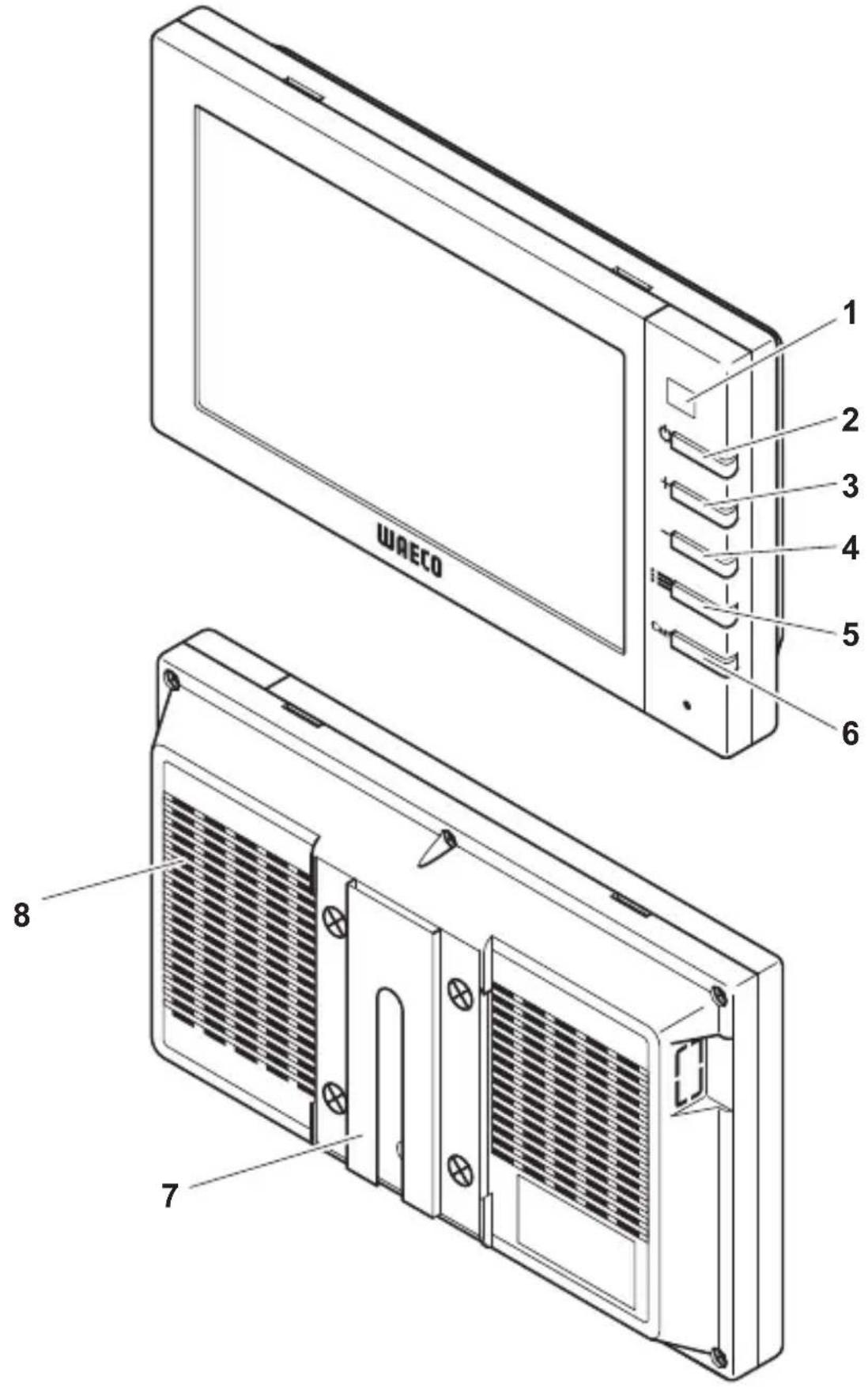
6.2 Control elements
The following control elements are located on the monitor:

1 Sensor window for the dimmer function. The brightness of the display is automatically adapted to the ambient light.
2 ⏻ Switches the monitor on and off. The button lights up red when the monitor is in standby. It lights up green when the monitor is switched on.
3 + 1. Increases the brightness. 2. Increases the value of the selected parameter if a menu is opened.
4 – 1. Reduces the brightness. 2. Reduces the value of the selected parameter if a menu is opened.

5 1. Switches the menu on.
- Calls up the parameters for setting.
The parameters are distributed over four screen pages in the following order:
Page 1: Picture
- Brightness
- Contrast
- Colour
- Volume
- Auto Dim
Page 2: Options
– Language: German, English, French, Italian, Dutch, Spanish, Portuguese, Russian
- Camera 1/Camera 2/Camera 3: Normal or Mirrored
- Sensitivity: Setting of the switching threshold for the night dimmer function
Page 3: Default
- Default: Default setting for all parameters
6 CAM Switches from one camera to the next.
7 Monitor bracket
8 Loudspeaker
7 Installing the LCD monitor
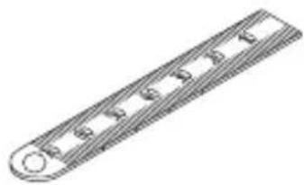
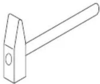
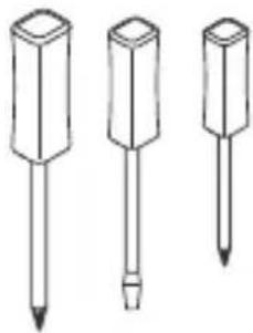
7.1 Tools required (fig. 1, page 3)
For installation and assembly you will need the following tools:
● Measuring ruler (4)
- Centre punch (5)
- Hammer (6)
- Drill head set (7)
- Drill (8)
- Screwdriver (9)
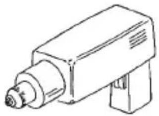
To establish and test the electrical connection, the following tools are required:
● Diode test lamp (1) or voltmeter (2)
● Insulating tape (10)
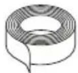
- Heat shrinking sleeve
● Hot air blower (11)
- Crimping tool (12)
● Soldering iron (optional) (13)
● Solder (optional) (14)
● Cable bushing sleeves (optional)
To fasten the cables you may require additional cable binders.
7.2 Installing the monitor

CAUTION! Beware of injury
Select the location of the monitor so that it cannot injure the passengers in the vehicle under any circumstances (e.g. sudden braking, road traffic accidents).
Observe the following installation instructions:
- Select an installation location that provides an unobstructed view of the monitor (fig. 6 and fig. 7, page 4).
● Never install the monitor in areas where your head could hit it or in the airbag deployment path. This could cause injury if the airbag opens.
● The monitor must not impair your vision when driving (fig. 8, page 5).
● The installation location should be flat. - Check that there is sufficient space underneath the installation location to attach the washers and nuts.
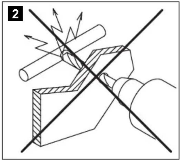
- Check beforehand that there is sufficient space on the other side for the drill head to come out (fig. 2, page 4).
- Bear in mind the weight of the monitor. Provide reinforcement if necessary (larger washers or plates).
● Make sure you can lay the connection cable to the monitor.
Choosing the installation location (fig. 11, page 7)
▶Place the monitor on the monitor bracket.
▶ Position the monitor and the attached monitor bracket provisionally.
▶ Mark the outlines of the corners of the support base on the dashboard.
▶Take the monitor off the monitor bracket.
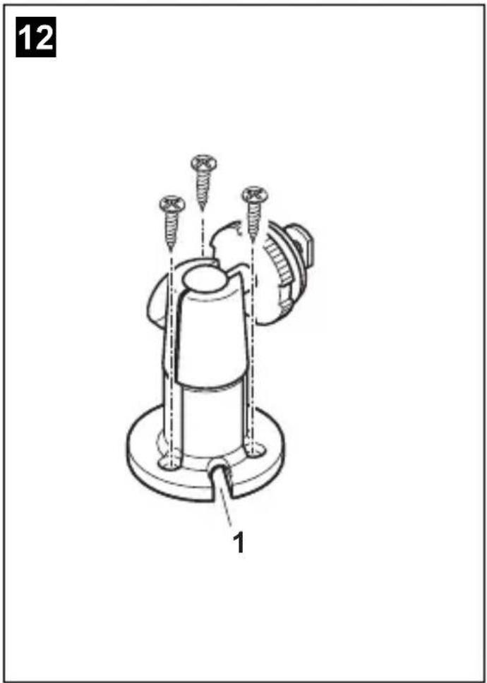
Screwing the monitor bracket onto the dashboard (fig. 12, page 7)
▶Hold the support base within the outlines marked beforehand.
▶Fasten the monitor bracket with the self-tapping screws.
Fastening the monitor
▶ Set the monitor on the monitor bracket and secure it with the knurled nut (fig. 11, page 7).
▶Slide the cover over the monitor bracket on the monitor.
7.3 Connecting the monitor electrically
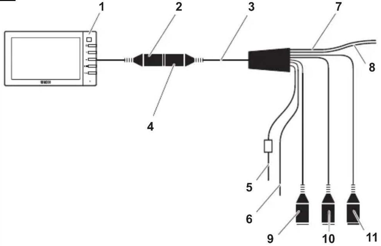
The circuit diagram for the LCD monitor can be found in fig. 14, page 8:
| No. Description | |
| 1 Monitor | |
| 2 20-pin socket | |
| 3 Monitor line | |
| 4 20-pin plug | |
| 5 | 12 – 24 V positive cable (red): connected to the positive pole of the ignition (connected positive, terminal 5) or the positive pole of the battery (terminal 30). |
| 6 Earth cable (black): connected to the negative pole of the voltage source. | |
| 7 Cable (green): control input for video input CAM1, such as for connecting the reversing light | |
| 8 Cable (white): control input for video input CAM2, such as for the side camera | |
| 9 6-pin CAM1 socket (connection to video source 1) | |
| 10 6-pin CAM2 socket (connection to video source 2) | |
| 11 6-pin CAM3 socket (connection to video source 3), with video signal detection) | |

NOTICE!
Cables and connections that are not properly installed will cause malfunctions or damage to components.
Correct installation of cables and connections ensures lasting and trouble-free operation of the retrofitted components.
Observe the following instructions when laying the connection cable:
- If possible, use original ducts for laying the cables, or other suitable options, such as ventilation grilles. If there are no existing ducts, you must drill a hole of 22 mm. Check beforehand that there is sufficient space on the other side for the drill head to emerge (fig. 2, page 4).
- Cover the holes with the feed through (fig. 12 1, page 7) in the base of the monitor bracket.
- To prevent damage to the cables, when laying them ensure that there is always sufficient distance to vehicle components which can become hot (lights, heaters, ventilators etc.).
- When laying the cables (fig. 3, page 4), make sure:
– They are not kinked or twisted
- They do not rub on edges
– They are not laid in sharp-edged ducts without protection.
Connecting the monitor as a reversing video system (fig. 14, page 8)
▶ Lay the connection cable for the monitor bracket on the dashboard.
Insert the plug of the monitor cable (2) into the socket (4) of the connection cable (3). Wait until you hear the plug snap in.

NOTICE! Beware of damage
Make sure the polarity is correct when connecting to a voltage source.
▶ Connect the red and black cables of the connection cable to a suitable voltage supply:
- Connect the red cable (5) to terminal 15 (ignition).
- Connect the black cable (6) to terminal 31 (earth).
▶If the monitor is to be activated when reverse gear is selected, connect the green cable (7) to the positive cable of the reversing light.

NOTE
If voltage is present in the green cable (7), the reversing camera will be activated automatically. The reversing camera has priority.
If the monitor is to be activated e.g. when the indicator is flashing, connect the following control cable to a positive cable of the indicator:
- white cable (8)

NOTE
If voltage is present in this control cable, the video input CAM2 will be activated.
This control cable is used as a signal cable for the activation of a side camera when an indicator is flashing, for example.
If necessary, connect the CAM1 socket (9) of the connection cable to the plug of the video source 1 (e.g. side camera).
If necessary, connect the CAM2 socket (10) of the connection cable to the plug of video source 2 (e.g. camera).

NOTE
Observe the power consumption of the video system. The cameras are equipped with heaters. A maximum current of 1.5 A can flow (three cameras in heating mode). Use a disconnector switch for direct connection to the battery. This allows you to disconnect the video system from the battery easily if you are no longer using the vehicle.
Connection for a reversing camera
If necessary, connect socket CAM3 (11) of the connection cable to the plug of the additional reversing camera.
8 Using the LCD monitor
8.1 Switching on the monitor
If the monitor is switched off, press the ⏻ button (fig. 10 2, page 6) to switch the monitor on.
▶The button lights up green.
√The picture appears.
8.2 Switching off the monitor
▶ Press the ⏻ button (fig. 10 2, page 6) to switch off the monitor.
▶The button lights up red.
√The picture disappears.
8.3 Setting the monitor
To set the monitor to suit your requirements, proceed as follows (fig. 10, page 6):
▶ Press the “≡” button (5) to call up the required parameter.
√The parameters to be set appear in the following order:
Page 1: Picture
-Brightness: 0 - 100
- Contrast: 0 - 100
- Colour: 0 - 100
- Volume: 0 - 100
- Auto Dim On, Off
Page 2: Options
– Language: German, English, French, Italian, Dutch, Spanish, Portuguese, Russian
- Camera 1/Camera 2/Camera 3: Normal or Mirrored
– Sensitivity: 1, 2
Setting of the switching threshold for the night dimmer function to avoid glare.
In dimming mode, the switching threshold can be set at two levels.
Page 3: Default
- Reset ("Default"): Default setting for all parameters
▶ Press the “+” button (3) or the “−” button (4) to set the required parameter.
▶ Press the “+” button (3) to increase the value of the selected parameter.
▶ Press the “−” button (4) to reduce the value of the selected parameter.
8.4 Setting the video source
Proceed as follows to set the video source (fig. 10, page 6):
▶ If you would like to switch to a different video source, press the "CAM" button (6).
√ The monitor changes the camera in the order "Camera 1 – Camera 2 – Camera 3".
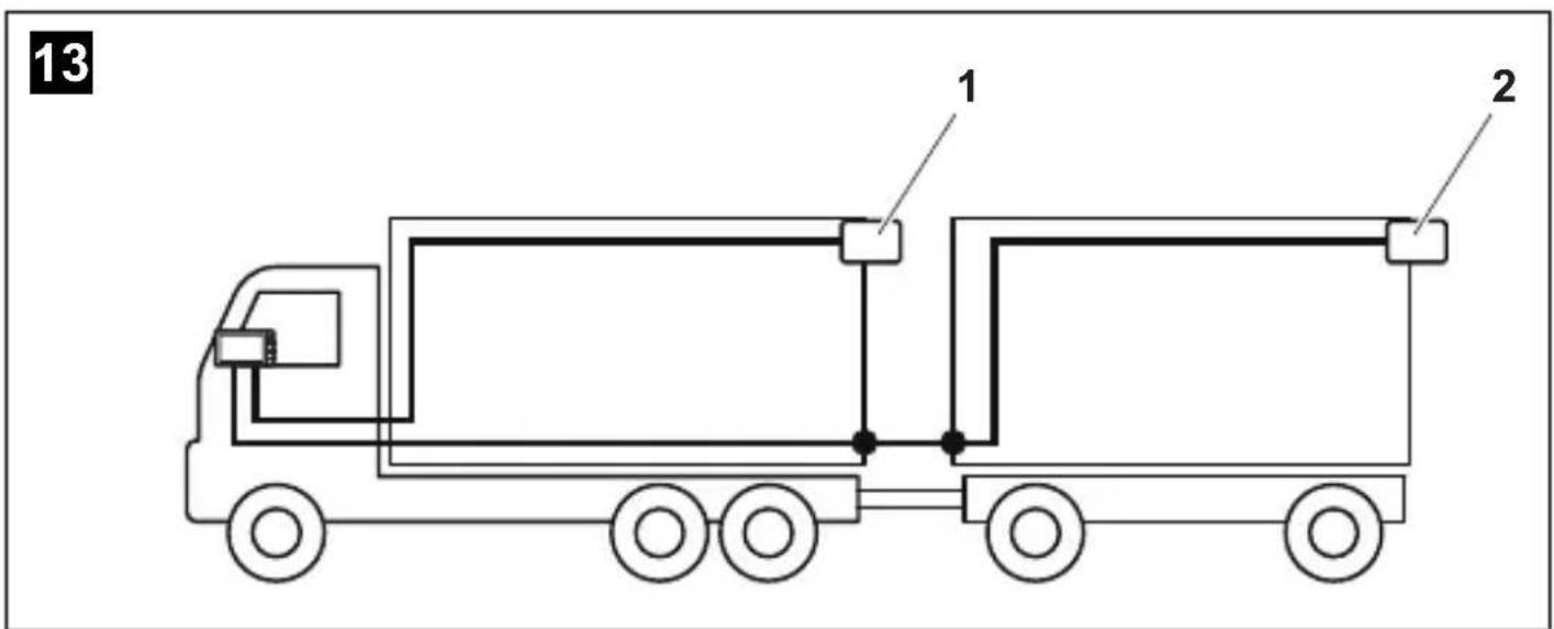
8.5 Detecting the trailer camera
This function is required when using a trailer camera (fig. 13, page 7) if the system is activated automatically via the reverse gear.
● One camera connected (e.g. vehicle without a trailer):
the camera connected to CAM1 (1) is activated.
- Two cameras connected (e.g. vehicle with a trailer):
the camera connected to CAM3 (2) is activated (CAM1 is inactive; CAM1 can only be activated via the "CAM" button)
9 Cleaning and caring for the LCD monitor

NOTICE! Beware of damage
- Do not use sharp or hard objects for cleaning, as these may damage the monitor.
- Remove the cable before cleaning the monitor to prevent short circuiting.
▶Clean the monitor with a soft, damp cloth from time to time.
10 Warranty
The statutory warranty period applies. If the product is defective, please contact the manufacturer's branch in your country (see the back of the instruction manual for the addresses) or your retailer.
For repair and guarantee processing, please send the following items:
- Defect components
● A copy of the receipt with purchasing date
● A reason for the claim or description of the fault
11 Disposal
Place the packaging material in the appropriate recycling waste bins wherever possible.

If you wish to finally dispose of the product, ask your local recycling centre or specialist dealer for details about how to do this in accordance with the applicable disposal regulations.
12 Technical data
| M55L M75L | ||
| Item no.: 9102100056 91021 | 100057 | |
| Type: Colour TFT LCD | ||
| Display size: 5" (12.7 cm) 7" | (17.8 cm) | |
| Brightness: approx. 350 cd/m2 | Approx. 400 cd/m2 | |
| Display resolution, H x V: 385 | 5 000 pixels | |
| Video standard: PAL/NTSC (automatic switching) | ||
| Operating voltage: | 12 – 30 V--- | |
| Power: Max. 10 W | ||
| Operating temperature: | -20 °C to 70 °C | |
| Storage temperature: | -25 °C to 80 °C | |
| Humidity: | Max. 85 % | |
| Vibration resistance: | 6 g | |
| Dimensions in mmW x H x D: | 146 x 87 x 26 | 190 x 110 x 26 |
| Weight: | 350 g | 400 g |
Approvals
The device has E13 certification.

6 Description technique
Dometic Australia Pty. Ltd.
1 John Duncan Court
Varsity Lakes QLD 4227
+61 7 55076000
+61 7 55076001
Mail: sales@dometic-waeco.com.au
AUSTRIA
Dometic Austria GmbH
Commercial : info@dometic.fr
SAV/Technique : service@dometic.fr
HONG KONG
WAECO Impex Ltd.
Suites 2207-2211 · 22/F · Tower 1
The Gateway · 25 Canton Road,
Tsim Sha Tsui · Kowloon
Hong Kong
+852 24611386
+852 24665553
Mail: info@dometic-waeco.com.hk
HUNGARY
Dometic Plc. Sales Office
Kerékgyártó u. 5.
H-1147 Budapest
+36 1 468 4400
+36 1 468 4401
Dometic Italy S.r.l.
Via Virgilio, 3
I-47100 Forlì
+39 0543 754901
+39 0543 756631
Mail: info@dometic.it
NORWAY
Dometic Norway AS
Skolmar 24
N-3232 Sandefjord
+47 33428450
+47 33428459
Mail: firmapost@waeco.no
POLAND
Dometic Poland Sp. z o.o.
Ul. Puławska 435A
02-801 Warszawa
Poland
+48 22 414 32 00
+48 22 414 32 01
Mail: info@dometic.pl
RUSSIA
Dometic RUS LLC
Komsomolskaya square 6-1
107140 Moscow
Russia
+7 495 780 79 39
+7 495 916 56 53
Mail: info@dometic.ru
SLOVAKIA
Dometic Slovakia Sales Office Bratislava
Nádražná 34/A
SK-900 28 Ivanka pri Dunaji
+421 2 45 529 680
Mail: bratislava@dometic.com
SPAIN
Dometic Spain S.L.
Avda. Sierra del Guadarrama, 16
E-28691 Villanueva de la Cañada
Madrid
+34 902 111 042
+34 900 100 245
Mail: info@dometic.es
SWEDEN
Dometic Scandinavia AB
Gustaf Melins gata 7
Dometic Switzerland AG
Riedackerstrasse 7a
CH-8153 Rümlang (Zürich)
+41 44 8187171
+41 44 8187191
Mail: info@dometic-waeco.ch
TAIWAN
WAECO Impex Ltd.
Taipei Office
2 FL-3 · No. 56 Tunhua South Rd, Sec 2
Taipei 106, Taiwan
+886 2 27014090
+886 2 27060119
Mail: marketing@dometic-waeco.com.tw
UNITED KINGDOM
Dometic UK Ltd.
Dometic House · The Brewery
Blandford St. Mary
Dorset DT11 9LS
+44 844 626 0133
+44 844 626 0143
Mail: sales@dometic.co.uk
UNITED ARAB STATES
Dometic Middle East FZCO
P. O. Box 17860
S-D 6, Jebel Ali Freezone
Dubai, United Arab Emirates
+971 4 883 3858
+971 4 883 3868
Mail: info@dometic.ae
UNITED STATES OF AMERICA
Dometic Marine Division
2000 N. Andrews Ave. Extension
Pompano Beach, FL 33069 USA
+1 954 973 2477
+1 954 979 4414
Mail: marinesales@dometicusa.com


