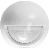
MD-W200i - Motion detector Esylux - Free user manual and instructions
Find the device manual for free MD-W200i Esylux in PDF.


| Product type | Passive infrared (PIR) motion detector |
| Brand | Esylux |
| Model | MD-W200i |
| Dimensions | Diameter 110 mm, depth 55 mm |
| Weight | Approx. 150 g |
| Power supply | 230 V ~ 50 Hz |
| Power consumption | Approx. 0.33 W |
| Detection area | 200° (2 x 100° separately adjustable) |
| Range | Approx. 12 m (mounting height 2.5 m) |
| Settings | Via control knobs (time and brightness) or optional infrared remote control Mobil-RCi-M |
| Switching capacity | 2300 W / 10 A (cos φ = 1), 1150 VA / 5 A (cos φ = 0.5) |
| Max. inrush current | 450 A / 200 µs |
| Time setting | 15 s to 16 min, pulse mode (1 s on / 9 s off) |
| Brightness setting | 2 to 2000 lux |
| Protection rating | IP 55 |
| Protection class | II |
| Operating temperature | -25 °C to +55 °C |
| Housing material | UV-resistant polycarbonate |
| Color | White (similar RAL 9010) or black (similar RAL 9005) |
| Recommended mounting height | 2.5 m |
| Main functions | Automatic on/off, test mode, permanent light (12 h), anti-vandalism function, relay deactivation in test cycle |
| Maintenance and cleaning | Clean with a soft, dry cloth. Do not use abrasive cleaners or solvents. |
| Safety | Disconnect power before installation. Use a 10 A circuit breaker. Installation only by qualified personnel. |
| Spare parts and repairability | No spare parts supplied. In case of defect, contact customer service or the dealer. |
| Manufacturer's warranty | 3 years from the date of purchase, subject to the conditions described in the manual. |
Frequently Asked Questions - MD-W200i Esylux
User questions about MD-W200i Esylux
0 question about this device. Answer the ones you know or ask your own.
Ask a new question about this device
Download the instructions for your Motion detector in PDF format for free! Find your manual MD-W200i - Esylux and take your electronic device back in hand. On this page are published all the documents necessary for the use of your device. MD-W200i by Esylux.
USER MANUAL MD-W200i Esylux
natural_image
Simple line drawing of a circular shape with a semicircular cutout, no text or symbols present.ESYLUX·
MD-W200i
www.esylux.com
BEWEGUNGSMELDER
MOTION DETECTORS
DÉTECTEURS DE MOUVEMENT
BEWEGINGSMELDERS
BEVÄGELSESSENSORER
RÖRELSEDETEKTORER
LIIKEILMAISIMET
natural_image
Technical line drawing of a mechanical component with no visible text or symbols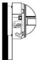
ABB./FIG. 4
4.1
4.2
4.3
4.4
4.5
4.6
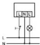
ABB./FIG. 5
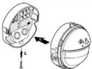
ABB./FIG. 6.1 ABB./FIG. 6.2
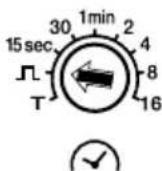

ABB./FIG. 7.1 ABB./FIG. 7.2
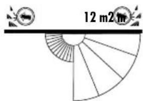
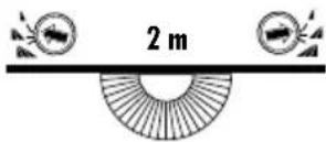
ABB./FIG. 7.3 ABB./FIG. 7.4
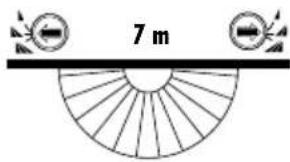
ABB./FIG. 8 ABB./FIG. 9
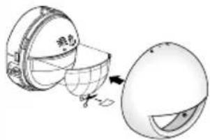
ABB./FIG. 10
Congratulations on your purchase of this high-quality ESYLUX product. To ensure proper operation, please read these user instructions carefully and keep them for future reference.
1 • SAFETY INSTRUCTIONS
CAUTION: Work on the 230 V power system must be carried out by authorised personnel only with due regard to the applicable installation regulations. Switch off the power supply before installing the system.
On the input side, the device is to be protected against short circuits with a 10-A circuit breaker.
$$ \mu = \text { Contact gap } < 1. 2 \mathrm{mm} $$
Use this product only as intended (as described in the user instructions). Changes or modifications to the product or painting it will result in loss of warranty. You should check the device for damage immediately after unpacking it. If there is any damage, you should not install the device under any circumstances.
If you suspect that safe operation of the device cannot be guaranteed, you should turn the device off immediately and make sure that it cannot be operated unintentionally.
2 • DESCRIPTION
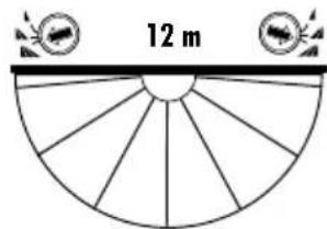
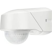
ESYLUX motion detectors are passive infrared detectors which react to moving heat sources (e.g. people or vehicles) (fig. 1 (1) head-on to detector (2) diagonally to detector). If the motion detector senses a change in thermal radiation inside its field of detection, depending on the set light value, it will activate the connected system (e.g. an automatic floodlight) for a preset length of time.
The ESYLUX MD-W200i motion detector features factory settings and the detector operates according to preset values (10 lux, 2 min.). The values can be individually modified. The device can be preset using either the settings on the device or, more conveniently, using the ESYLUX Mobil-RCi-M remote control (available as an option).
3 • INSTALLATION/ASSEMBLY/CONNECTION
Before installing the device, observe the following:
- Turn off the power supply.
- Information concerning range is based on an installation height of 2.50 m (the field of detection will vary according to this height).
- For optimum performance (i.e. maximum range), position the device so that people/vehicles are moving parallel to the detector (fig. 1).
-
Make sure that the detector has a clear line of sight, as infrared beams cannot penetrate solid objects.
-
To avoid influencing the light sensor, maintain a minimum distance of 1 m in relation to the connected lighting and do not point light sources directly at the detector.
- When installing the device, bear in mind the surrounding area e.g. neighbouring properties or the distance to the road.
- The motion detector should only be installed on a stable, flat surface (wall).
Remove the covering cap by turning it slightly to the left (fig. 2.1). The wall base unit and sensor are connected. For installation purposes, separate the two parts. Fit the screwdriver into the side opening, lever in the direction of the sensor and pull the detector away from the wall connector base (fig. 2.2). Feed the cable into the detector and mount the wall base unit in the required position (fig. 3). The hole distance is 60 mm so that the wall base can also be mounted on standard recessed-mounted boxes (fig. 3.1). For surface-mounted boxes, refer to fig. 3.2.
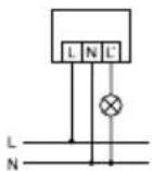
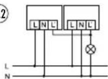
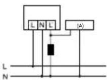
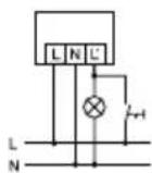
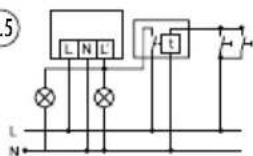
Connect the motion detector according to the circuit diagram (fig. 4).

CAUTION: The maximum inrush current must not be exceeded connecting to capacitive loads such as electronic ballasts orescent lamps with parallel compensation.
(4.1) Standard operation.
(4.2) Parallel connection of max. 8 devices.
(4.3) When connecting inductors (e.g. relays, contactors, ballasts) the use of a filter (A) may be necessary.
(4.4) Standard operation with additional continuous function through external switches.
(4.5) Parallel connection with automatic stairwell light.
(4.6) Standard operation with the additional possibility of switching on by hand.
Press the sensor into the wall base until it clicks into place and secure it with the safety screw (fig. 5). NB: The motion detector must always be mounted so that the sensor faces forwards and downwards.
4 • START-UP AND SETTINGS
After the device has been successfully installed and the power supply switched on, the device will perform a self-test (lasting about 60 seconds). During this test, the focus LED will flash and the connected system (can be switched off optionally – see p. 13) will come on. Once this time has elapsed, the device will be operational and will function according to the factory settings (10 lux, 2 min).

Note: to prevent tampering, the "Relay OFF during the self-test" is disabled in the factory settings. Activation is only possible during the self-test.

Test mode
The time setting and light value switches are located behind the covering cap. Set the time setting switch (fig. 6.1) to T for test. During test mode, irrespective of ambient brightness, if motion is detected, the system will switch ON for 1 second and OFF for 2 seconds.
The following possibilities are available to adjust the field of detection to the surrounding area:
- Adjust the range on the left and the sensor field on the right by mechanically adjusting the internal lens mask (fig. 7).
- Use the supplied covering cap to mask specific areas (fig. 8).
Once you have established the field of detection, turn the time setting switch to the required ON period (fig. 6.1) (Impulse 15 seconds - 16 minutes) and adjust the light value (fig. 6.2) (2 - 2000 lux) according to your requirements. Impulse means that the device is activated for 1 second followed by a break of 9 seconds in which no movement is detected.
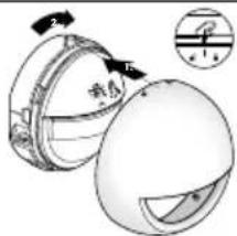
NOTE: When turning the light value switch (starting from the moon symbol), if the current ambient brightness is reached or exceeded, the focus LED will light up (as a setting aid). The LED automatically goes out after 2 seconds. Depending on the set light value and any detected movement, the focus LED will flash twice. The motion detector also switches the system on according to the set ON period. Place the covering cap on the sensor and lock it by turning it gently to the right (fig. 9).
5 • REMOTE CONTROL
All settings programmed by remote control are permanently stored in the memory and will not be lost in the event of a power failure.
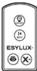
Using the remote control Mobil-RCi-M (fig. 10) the settings can be easily programmed without needing to climb a ladder or use any tools. For optimum reception, when programming the settings, point the remote control at the motion detector. Please note that if the sun shines directly on the sensor, the standard detection range of approx. 6 m may be dramatically reduced owing to the sun's infrared rays.
Acknowledgement of commands
If the command is acknowledged and performed: Focus LED flashes 3 times.
6 • PRACTICAL ADVICE
- Small animals, nearby trees or bushes moving in the wind may cause the floodlight to switch on.
- The detector's range can be dramatically reduced by objects moving towards it, rather than parallel with it.
| Button Operating the device | |
 | Continuous lighting ON/OFFSystem can be switched ON or OFF, independently of motion or ambient brightness, for 12 hours max.NB: To prevent tampering, the continuous lighting OFF function is disabled in the factory settings. Activation is only possible during the self-test. Switch the power supply on and press the button during the self-test. The continuous light OFF function is now enabled.To disable this function, press the button during the self-test. (Resets factory settings).Operating continuous light mode ON/OFFContinuous light mode OFF disabled – Every time the button is pressed, the light switches ON for 12 hours.Continuous light OFF enabled – Pressing the button once switches the light ON for 12 hours. If the button is pressed again, the light will switch OFF for 12 hours. Press the button again to switch the light OFF – ON – OFF – ON.NOTE: After the maximum 12-hour „Permanent ON/OFF“ period has expired, or if the button is pressed, the detector will switch to Automatic mode."RELAY OFF" during the self-testFor use on automatic stairwell lights in connection with impulse time setting.Switch the power supply on and press the (12h on/off) button during the self-test. The "RELAY ON" during the self-test function is now disabled.To reactivate this function, press the (12h on/off) button during the self-test. |
 | Storing the current light intensity valueStores the current light intensity value. To overwrite this value, turn the LUX switch or press the button again. |
 | Cancels the time settings / 12 hours ON/OFF |
 | ResetCancels the time settings. Exits continuous lighting ON/OFF.Reset – During the self-test (after switching the power off).Resets the device to the default settings. Cancels all values set by remote control and resets all functions. The device operates according to the preset factory settings (10 lux/2 min.).NB: If the Continuous light OFF function is used further, it must be re-enabled. |


7 • DISPOSAL

NOTE: this device must not be disposed of as unsorted behold waste. Used devices must be disposed of correctly. Act your local town council for more information.
8 • ESYLUX MANUFACTURER'S GUARANTEE
ESYLUX products are tested in accordance with applicable regulations and manufactured with the utmost care. The guarantor, ESYLUX Deutschland GmbH, Postfach 1840, D-22908 Ahrensburg, Germany (for Germany) or the relevant ESYLUX distributor in your country (visit www.esylux.com for a complete overview) provides a guarantee against manufacturing/material defects in ESYLUX devices for a period of three years from the date of manufacture. This guarantee is independent of your legal rights with respect to the seller of the device. The guarantee does not apply to natural wear and tear, changes/interference caused by environmental factors or damage in transit, nor to damage caused as a result of failure to follow the user or maintenance instructions and/or as a result of improper installation. Any illuminants or batteries supplied with the device are not covered by the guarantee. The guarantee can only be honoured if the device is sent back with the invoice/receipt, unchanged, packed and with sufficient postage to the guarantor, along with a brief description of the fault, as soon as a defect has been identified. If the guaranteed
claim proves justified, the guarantor will, within a reasonable period, either repair the device or replace it. The guarantee does not cover further claims; in particular, the guarantor will not be liable for damages resulting from the device's defectiveness. If the claim is unfounded (e.g. because the guarantee has expired or the fault is not covered by the guarantee), then the guarantor may attempt to repair the device for you for a fee, keeping costs to a minimum."
• TECHNICAL DATA
| MAINS VOLTAGE 230 V ~ 50 Hz | |
| POWER CONSUMPTION IN W approx. 0,33 | |
| FIELD OF DETECTION 200° (2 x 100° can be set independently) | |
| RANGE approx. 12 m at an installation height of 2.50 m | |
| SETTINGS | Mechanically using the setting controls, electronically using the infrared remote control |
| SWITCHING CAPACITY | 230 V ~ 50 Hz, 2300 W/10 A (cos φ = 1), 1150 VA/5 A (cos φ = 0,5) |
| MAX INRUSH CURRENT 450A/200μs | |
| TIME SETTING approx. 15 sec. - 16 min. | |
| APPROX. LIGHT VALUE 2 - 2000 lux | |
| PROTECTION TYPE, PROTECTION CLASS IP 55, II | |
| TEST SYMBOL TÜV/SÜD | |
| OPERATING TEMPERATURE RANGE -25 °C ... +55 °C | |
| HOUSING UV stabilised polycarbonate | |
| COLOURS white, similar to RAL 9010, black, similar to RAL 9005 | |
| MEASUREMENTS ∅ 110 mm, depth: 55 mm |
Technical and design features may be subject to change

FR • NOTICE DE MONTAGE ET D'UTILISATION

- • SAFETY INSTRUCTIONS
- • DESCRIPTION
- • INSTALLATION/ASSEMBLY/CONNECTION
- Before installing the device, observe the following:
- • START-UP AND SETTINGS
- Test mode
- • REMOTE CONTROL
- Acknowledgement of commands
- • PRACTICAL ADVICE
- • DISPOSAL
- • ESYLUX MANUFACTURER'S GUARANTEE
- FR • NOTICE DE MONTAGE ET D'UTILISATION
Brand : Esylux
Model : MD-W200i
Category : Motion detector